
ISSN: 2321 9653; IC Value: 45.98; SJ Impact Factor: 7.538

Volume 10 Issue X Oct 2022 Available at www.ijraset.com


ISSN: 2321 9653; IC Value: 45.98; SJ Impact Factor: 7.538

Volume 10 Issue X Oct 2022 Available at www.ijraset.com
Abishek V M1 , Faizudeen N2 , Chandru S H3 , Palani .R4 Bachelor of Engineering in Mechanical Engineering
VEL Tech High Tech, DR. Rangarajan & DR. Sakunthala Engineering College,Avadi, Chennai 600 062
Abstract: In this project, the surface of a cylinder Liner in a diesel engine is coated with ceramiccoating powders by the plasma spray technique using Ansys and its surface behavior is subsequently analyzed. The purpose of this study is to analyze with tribological effects of surface coating for a Liner in frictional mechanism. In, with and without coated cylinderliner was analyzed with Ansys software. The modeling and analysis of the cylinder liner is carrying by the catia and ansys software. Also, the combustion flow analysis of the cylinder liner is carried by Ansys software. From the obtained test results, it was found that the coated liner having improved properties in towards the diesel engine performance. The results show less deformation and fewer scratches due to wear on the Titania coated Liner ascompared to uncoated one.
Keywords: Coatings; Structure; Adhesion; Wear resistance; Plasma Spray Technique

Thermal insulation reduces in cylinder heat transfer from the engine combustionchamber as well as reducing component structural temperatures. Containment of heat also contributes to increased in cylinder work and offers higher exhaust temperatures for energy recovery. Ceramics have a higher thermal durability than metals; therefore it is usually not necessary to cool them as fast as metals. Low thermal conductivity ceramics can be used to control temperature distribution and heat flow in a structure. Thermal barrier coatings (TBC) provide the potential for higher thermal efficiencies of the engine, improved combustion and reduced emissions. In addition, ceramics show better wear characteristics than conventional materials. Lower heat rejection from the combustion chamber through thermally insulated components causes an increase in available energy that would increase the incylinder work and the amount of energy carried by the exhaust gases, which could be also utilized.
Thermal barrier coatings are becoming increasingly important in providing thermal insulation for LHR engine components. For such an engine the insulating material must possess low thermal conductivity, low specific heat, high strength, high fracture toughness, high thermal shock resistance, low friction and wear resistance, high temperature capability, high expansion coefficient and chemical inertness for high resistance to erosion and at all temperature ranges. Among those properties, thermal expansion coefficient and thermal conductivityseem to be the most important. In this study materials which are favourable to achieve low heat rejection are considered.
There are two ways that an internal combustion piston engine can transform combustion into motive power: The two stroke cycle and the four stroke cycle. A single cylinder two stroke engine produces power every crankshaft revolution, while a single cylinder four stroke engineproduces power once every two revolutions. Older designs of small two stroke engines produced more pollution than four stroke engines. However, modern two stroke designs, like the Vespa ET2 Injection utilise fuel injection.
Hard aluminium titanium coating are fine pores and no micro crack were homogenously distributed. Aluminium titania coating also contained splat like particles enriched in Ti, Fe and Si with respect to pure alumina. The porosity was found to be 7.1%for alumina coating and 6.71% for alumina titania coating. The micro hardness of alumina titania coating was lower than aluminium coating. Alumina based coating for high temperature anti wear application were manufactured byplasma spraytechnique.
ISSN: 2321 9653; IC Value: 45.98; SJ Impact Factor: 7.538

Volume 10 Issue X Oct 2022 Available at www.ijraset.com
Energy conversation and efficiency have always been the question of engineering concerned with internal combustion. This work aim making it is for manufacturer to choose the coating material for engine coating purpose and surface properties for operating them in the working period.

Plasma thermal spray of ceramic oxide coating on carbon steel with enhanced wear and corrosion resistance (2014). The alumina titania chemical composite resulting from the spray technique produced a coating with superior mechanical and chemical properties. The hardness and wear test results signify that splat delamination and wear rate were negligible for the coated samples. The ceramic oxide had higher charge transfer resistance comparedto the uncoated sample, It had higher resistance to compare pure carbon steel.
Mullite zirconia zirconium titanate ceramic composites (2019).The ceramic material and the crystalline phases were evaluated by the rietveld method as well as the texture properties. The achieved micro structure consisted in inter locked multiphase ceramic with zirconia grains. It can be concluded that the dense and interlocked refractory micro structure and relative high mechanical properties of the developed zirconia and titanate materials encourages several high temperature applications.
Mechanical properties and structural of zirconia mullite ceramic (2019). Zirconia mullite nano composite were fabricated by in site controlled fabrication by Si Al Zr O. Amorphorus which were first treated at high temperature for crystallization to obtain zirconium mullite ceramic.
The deformation enhanced re crystilization of titanium(2019). Titanium is a common accessory mineral that is useful in both pressure and temperature conditions. However titanite as property to re crystilling during metomorphism fluid flow and deformation which result to modification.
Mechanical stress analysis in cylinder penkins 1306 diesel engine. The thermal stress and mechanical friction inside the combustion chamber may cause failure on cylinder liner.It decreases liners life in engine.
Investigated on Mass loss and wear mechanisms of HVOF sprayed multi component white cast iron coating. In this work, multi component white cast iron was applied by HVOFthermal spray process as alternative to other manufacture processes. Effects of substrate type, substrate pre heating and heat treatment of coating on mass loss have been determined by rubber wheel apparatus in accordance with ASTM G 65. Furthermore, influence of heat treatment of coating on wear mechanisms was also determined by scanning electron microscopy analysis. Heat treated coatings presented mass loss three times lower than as sprayed coatings. Furthermore, wear mechanisms of as sprayed coating are micro cutting associated with cracks close to unmelted particles and pores. In heat treated coating, lesser mass loss is due to sintering.
Investigated on aspects of microstructure on the synergy and overall material loss of thermal spray coatings in erosion corrosion environments .The influence of microstructure on the overall material loss in erosion corrosion environments is presented for WC Co Cr coatings applied by (i) High Velocity Oxy Fuel (HVOF) and (ii) Super Detonation Gun (D Gun) processes. The study is focused on understanding the synergy effect (here defined asthe enhancement of erosion due to corrosion effects) on material loss when two different microstructures are formed and also the influence of chemical composition of the coating. Experiments showed that HVOF coatings have a slightly lower corrosion resistance than the Super Detonation Gun (D Gun) coatings but higher overall erosion corrosion resistance. It is important to point out that HVOF and Super D Gun coating microstructures vary depending on parameters of application and therefore the results presented in this paper cannot be generalised.
ISSN: 2321 9653; IC Value: 45.98; SJ Impact Factor: 7.538 Volume 10 Issue X Oct 2022 Available at www.ijraset.com

In this work a particular case is presented to establish a link between the coating composition, microstructure and erosion corrosion performance for WC Co Cr coatings when different microstructures are formed.
Investigated on Comparison of HVOF and plasma sprayed alumina titania coatings microstructure, mechanical properties and abrasion behaviour, they evaluated the microstructure, mechanical properties and abrasion wear resistance of alumina titania ceramic coatings deposited with nano and micro structured powders by high velocity oxygen fuel (HVOF) and plasma spray (PS) processes. The deposition guns have a strong influence on the mechanical properties and abrasive wear resistance of the coatings, but the powders do not. The coatings deposited by HVOF are significantly harder and tougher, and their abrasion resistance is two three fold higher. Plastic microcutting plays the predominant role in abrasion wear of the coating deposited by HVOF. A combination of brittleness and porosity results in fracture that dominates the abrasion wear of plasma sprayed coatings. Theabrasion resistance measured follows an Evans Marshall equation modified to account for the effects of porosity.
K. T. VALENTEInvestigated on Corrosion resistance properties of reactive plasma sprayed titanium composite coatings Among thermal spraying methods, an attractive technical possibility lies in the fabrication of protective coatings or Ž. free standing components by means of reactive plasma spraying RPS techniques. Using reactive gases, such as nitrogen or methane, it is possible to synthesize hard nitride or carbide phases in reactive metals like Ti, Cr or Al. In this investigation Ž.composite titanium nitrides rtitanium coatings produced by RPS througha controlled atmosphere plasma spray system CAPS, were electrochemically tested to evaluate their corrosion behaviour. Two environments were selected: a neutral 0.5 M Na Cl and an acid aqueous solution 0.5 M NaCl q1 M HCl . The influence of porosity and nitrogen content on the corrosion resistance has been investigated. Polarization curves of coated samples, detached coatings, AISI304 substrate and commercially pure titanium Ž. grade 2 , are also reported and discussed. The corrosion resistance of coated samples was found to be mainly dependent on porosity values, thus optimization of plasma spraying parametersassumes a fundamental role to obtain wear and corrosion resistant deposits.
L. S PAL, ADEORE, A CHOUDARY
Investigated the research of Thermal Barrier Coatings (TBC) microscopic level (2014). The main focus of this work was to study the application of TBCs as the top layer onthe head of the piston. To scientifically and analytically select the correct and most suitable powder for the application, steady state thermal analysis was performed. And then the Aluminium samples were coated with the best suitable powder which was found to be partially stabilised zirconia bythe means of plasma spray coating. The authors conclude the following:
From thermal analysis, it can be concluded that zirconia comes out as a superior option compared to alumina and titania ceramic powders as TBCs. Zirconia can be selected as a coating material for piston head or any other similar application where substrate is subjected to similar temperature and stress conditions. Use of yettria stabilized zirconia in Al piston leads to reduced heat flux, increased top surface temperature, reduced temperature at piston skirt and bottom area. This reduces the damage to the piston, increasing its service period and efficiency. Various piston damages that occur at the piston head are mostly due low hardness of the top surface.

Application of stabilised zirconia as TBC by the means of plasma spray coating with specific parameters increases the hardness of the sample that reduces piston damages. Salt spray study was performed to measure corrosion resistance of the engine piston due to acidicand humid conditions which are observed during early morning start, cold start etc. Uncoated sample was affected by the white rust at the end of 12 hours. Sample coated with zirconia showed no signs of rust at the end of 72 hours. Hence, coated pistons have better corrosion resistance. Surface roughness test show that the application of TBC increases the roughness in very small amounts and does not affect the engine operations.
Investigated on the thermally sprayed titanium sub oxide coatings for piston ring/cylinder liners under mixed lubrication and dry running condition. Two new sub stoichiometric titania (TiOx) coatings designated for cylinder liner application were deposited on specimen of grey cast iron GG20HCN with high carbon content by plasma spraying. First, a TinO2n−1 coating was prepared by atmospheric plasma spraying (APS) using a sintered and agglomerated Magnéli type spray powder. Second a TiO1.95 x coating was deposited with a vacuum plasma spray (VPS) process using a commercial, fused and crushed TiO1.95 powder.
ISSN: 2321 9653; IC Value: 45.98; SJ Impact Factor: 7.538 Volume 10 Issue X Oct 2022 Available at www.ijraset.com


Mullite Ceramics consist of mullite (3Al2O3. 2SiO2), alumina (Al2O3) and glass (SiO2). Sintered Mullite Ceramics have porosity up to 10%, which may be considerably reduced by increasing the content of glass phase above 10%. mullite has a much lower thermal expansion coefficient and higher thermal conductivity, and is much more oxygen resistant than YSZ. For the applications such as diesel engines where the surface temperatures are Lower than those encountered in gas turbines and where the temperature variations across the coating are large, mullite is an excellent alternative to zirconia as aTBC material. Its low thermal expansion coefficient creates a large mismatch with the substrate. The low TEC of mullite is an advantage relative to YSZ in high thermal gradients and under thermal shock conditions. However, the large mismatch in TEC with metallic substrate leads to poor adhesion. To address this problem, multilayer systems are under development which minimize the thermal expansion mismatch stresses whilemaintaining chemical and phase stability .
Aluminum titanate is a ceramic material consisting of a mixture of alumina and titania. Al2TiO5. Aluminium titanate is prepared by heating of a mixture of alumina and titania at temperature above 2460 F (1350 C). The powder is then sintered at a temperaturein the range 2550 2910 F (1400 1600 C) in air atmosphere. Pure Aluminum Titanate is unstable at the temperatures above 1380 F (750 C) when the solid solution decomposes into two separate phases as Al2O3 and TiO2. Aluminum Titanate ceramics are doped with MgO, SiO2 and ZrO2 in order to stabilize the solid solution structure.
ISSN: 2321 9653; IC Value: 45.98; SJ Impact Factor: 7.538 Volume 10 Issue X Oct 2022 Available at www.ijraset.com

The distinctive property of Aluminum Titanate ceramics is their high thermal shock resistance which is a result of low coefficient of thermal expansion But it has low mechanical strength. When this is heated itexpands along two axes and contracts along the third axis.
It is a ceramic material and exists in monoclinic form at temperatures below 11700C. At 23700 C it changes to tetragonal. Structural change is accompanied by volume change .Inspite of many advantages the structural changes occurring due to the temperature changes is the main disadvantage of this material. These changes are the root cause for volume changes which may cause cracking or structural failure. Towards certain degree these changes canbe mitigated by the additions of some oxides like MgO, CaO, Y2O3 and these oxides will depress allotropic transformation and help in stabilizing the structure at any temperature.The values of difference in temperature, Δt , is calculated for five different insulation ceramic materials for 0.1 mm thickness of insulation. It is seen from the table the highest difference in temperature is obtained for the substance Gd2Zr2O7 compared to Zirconia or partially stabilized Zirconia like YSZ. The other substance Lathanum Zirconate also has highest difference in temperature that may be considered suitable candidate for insulation. But the substance Gadolnium and Lanthanum Zirconate has to undergo other tests and it should be proved to be stable mechanically and at present Zirconia and YSZ are the components used for thermal insulation in the experimental studies widely.Fifteen different thermal barrier coatings ceramic powders have been evaluated. Using advanced modelling techniques. This study aimed to predict engine conditions and performance. This has been done with thick coatings rather thin considered for diesel or SI engines. The authors have also considered bond coat composition, coating design, microstructure and thickness effect on properties, durability and reliability. In this study spray parameters have been optimized for each powder. Coatings have been evaluated for each powder. Coatings have been evaluated for their performance especially with regard to fatigue failure and aging behaviour. In another study partially stabilized zirconia coatings forengine combustion has been evaluated and results indicate that the coating PSZ is not effective for a diesel engine since they are transparent to the thermal radiation and this conclusion has been arrived based on thermodynamic study. .
Coating is a covering that is applied to an object. The aim of applying coatings is to improve surface properties of a bulk material usually referred to as a substrate. One can improve appearance, adhesion, wet ability, corrosion resistance, wear resistance, scratch resistance, etc.. They may be applied as liquids, gases or solids. Coatings can be measured and tested for proper opacity and film thickness by using a Drawdown card.
Nano coating is a recently developed technology used for coating any kind of material in hard coating and low friction coating both in which coating is done at nano scalethat is of the order of 10 9 . The two major types of nano coating are
1) Physical vapour deposition (PVD)
2) Chemical vapour deposition (CVD)
3) Plasma Spray Coating
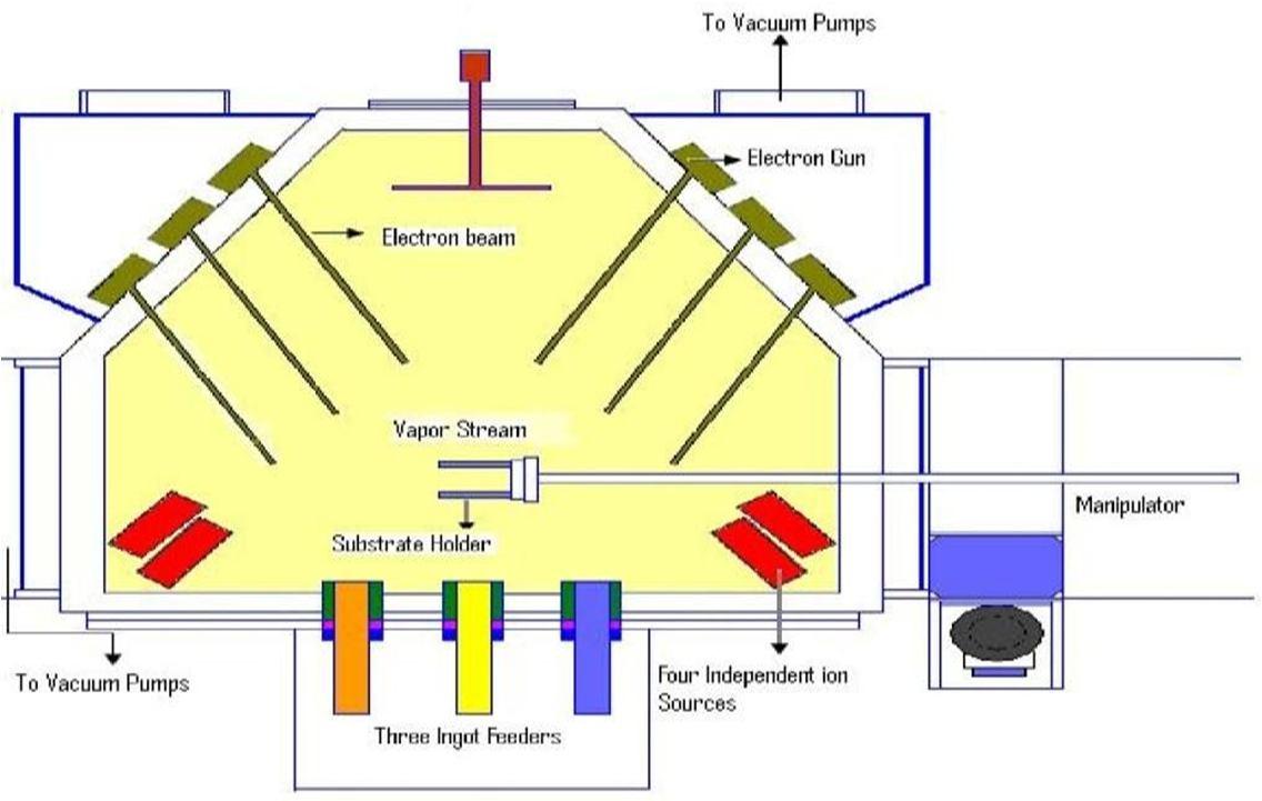
Thin film deposition is a process applied in the semiconductor industry to grow electronic materials and in the aerospace industry to form thermal and chemical barrier coatings to protect surfaces against corrosive environments and to modify surfaces to have the desired properties. The deposition process can be broadly classified into physical vapour deposition (PVD) and chemical vapour deposition (CVD). In CVD, the film growth takes place at high temperatures, leading to the formation of corrosive gaseous products, and it mayleave impurities in the film. The PVD process can be carried out at lower deposition temperatures and without corrosive products, but deposition rates are lower and it leaves residual compressive stressin the film. Electron beam physical vapour deposition, however, yields a high deposition rate from 0.1 μm / min to 100 μm / min at relatively low substrate temperatures, with very high material utilization efficiency.

ISSN: 2321 9653; IC Value: 45.98; SJ Impact Factor: 7.538

Volume 10 Issue X Oct 2022 Available at www.ijraset.com
Parameters of PVD is given by
1) Deposition Chamber Vacuum Pressure: 10 4 torrNo. of electron guns: 6
2) Accelerating Voltage: 20kv 25kvEvaporation rate: 10 2 g/cm2 sec
Refractory carbides like titanium carbide and borides like titanium boride and zirconium boride can evaporate without undergoing decomposition in the vapour phase. These compounds are deposited by direct evaporation. In this process these compounds, compacted in the form of an ingot, are evaporated in vacuum by the focused high energy electron beam and the vapours are directly condensed over the substrate. Certain refractory oxides and carbides undergo fragmentation during their evaporation by the electron beam, resulting in a stoichiometry that is different from the initial material. For example, alumina, when evaporated by electron beam, dissociates into aluminium, AlO3 and Al2O. Some refractory carbide like silicon carbide and tungsten carbide decompose upon heating and the dissociated elementshave different volatilities. These compounds can be deposited on the substrate either by reactive evaporation or by co evaporation. In the reactive evaporation process, the metal is evaporated from the ingot by the electron beam. The vapours are carried by the reactive gas, which is oxygen in case of metal oxides or acetylene in case of metal carbides. When the thermodynamic conditions are met, the vapours react with the gas in the vicinity of the substrate to form films. Metal carbide films can also be deposited by co evaporation. In this process, two ingots are used, one for metal and the other for carbon. Each ingot is heated with different beam energy so that their evaporation rate can be controlled.
The substrate on which the film deposition takes place is ultrasonically cleaned and fastened to the substrate holder. The substrate holder is attached to the manipulator shaft. The manipulator shaft moves translational to adjust the distance between the ingotsource and the substrate. The shaft also rotates the substrate at a particular speed so that the film is uniformly deposited on the substrate. A negative bias D.C. voltage of 200 V 400 V is applied to the substrate Focused high energy electrons from one of the electron guns preheat the substrate.

Electron beam deposition physical vapour method
Functionally Graded Coatings are typically ceramic composites based on zirconia, alumina, and titanium. The high hardness, wear resistance and good chemical stability of TBCs make them very desirable in cutting tool applications. Functionally Graded Coating provides good resistance against the corrosive, high temperature environment of aircraft engines as well. Wear resistance can increase between 200 to 500% with the addition of a FunctionallyGraded Coatings to a material. Chemical vapor deposition (CVD), plasma vapour deposition (PVD), and electron beam physical vapor deposition (EBPVD) are the primary deposition methods for these coatings.
ISSN: 2321 9653; IC Value: 45.98; SJ Impact Factor: 7.538

Volume 10 Issue X Oct 2022 Available at www.ijraset.com
For the motorsport sector we offer a range of Zirconia thermal barriers which are used on high temperature components such as exhaust pipes and turbo's helping to reduce under bonnet temperatures by up to 50 C and improving engine performance.
A Zirconia treatment will reduce heat transfer through exhaust outlets which in turn maintains higher internal gas temperatures and faster transfer ratesresulting in a more efficient exhaust system.
1) The reduction in heat loss through the exhaust system also reduces the under bonnet temperature which can effect other engine components.
2) In particular, the Zirconia thermal barrier can help to protect internal wiring and and minimise the threat of electronics from shorting.
3) High temperature corrosion resistance.
4) Zirconia based ceramics are used in heat insulation applications as thermal barriers to improve efficiency and service life of components in high temperature service.
5) These materials are generally plasma sprayed over an appropriate bond coat. Stabilisers such as magnesia, ceria, calcia and yttria are alloyed withthe zirconia to help minimise phase transformation that can cause volumechanges within the coating, which can in turn lead to coating cracking during service.
6) Key applications are graphite trays used for sintering of carbide, gas turbine

Cylinder liners are generally made from grey cast iron because it is easily cast and has self lubricating properties due to the graphite flakes for, some modern engines spheroidal graphite or nodular graphite is used. This has greatermechanical strength, but has the same self lubricating properties. The critical part of any liner is the upper section were the temperature andpressure conditions are at their most difficult. Cooling is required to maintain strength and the temperature variations must be maintained within set limits in order to avoid cracking. Rapid change of temperature due to the rapid variation in cylinder condition or cooling water temperature can result in cracking.
There arethree main cause of damage to the liner material;
1) Corrosion: Caused bythe acidic products of combustion
2) Abrasion: Caused by solid particles breaking through the lubricant film
3) Friction: Break down of the lubricating oil film leading to metal to metalcontact
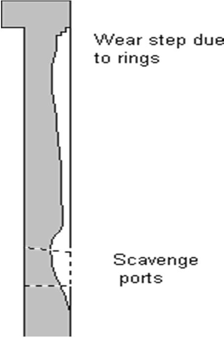
Normal liner wear exists for the reasons given above. Wear rates are greatest towards the top of the stroke due to the high temperatures thinning out the oil film and high gas pressure behind the piston rings forces the land into contact with the liner wall. In addition, piston is moving slowly at the end of its stroke and a good oil wedge cannot be formed. Wear rates reduce lower down the stroke because pressure and temperature conditions are less arduous and piston speed has increases.
ISSN: 2321 9653; IC Value: 45.98; SJ Impact Factor: 7.538

Volume 10 Issue X Oct 2022 Available at www.ijraset.com
At the bottom end of the stroke wear rate increases again due to reduce piston speed, but also due to the scouring effect of the in coming scavenging air.The reduced temperature increases the viscosity of the oil so reducing its ability to spread evenly. Long stroke engines are sometimes provided with quills at the bottom of the stroke.
A metal may be described as a material which is solid at room temperature has relatively high density, high melting temperature, low specific heat, good electrical and thermal conductivity, strength, stiffness, hardness,toughness, etc.
By engineering materials, we mean materials used for manufacturing engineering components in industry. Materials form one of four M’s (Men, Material, Machines and Money) which plays a vital role for the developmentand flourishment of a country. The study of engineering materials, namely ferrous and non ferrous metals, metal alloys, non metals, their grain structure, properties and applications etc. is termed as material science.
There are thousands of materials available for use in engineering applications. Most materials fall into one of three classes that are based on the atomic bonding forces of a particular material. These three classifications are metallic, ceramic and polymeric. Additionally, different materials can be combined to create a composite material. Within each of these classifications, materials are often further organized into groups based on their chemical composition or certain physical or mechanical properties. Composite materials are often grouped by the types of materials combined or the way the materials are arranged together. Below is a list of some of the commonly classification of materials within these four general groups of materials.

Ferrous metals and alloys (irons, carbon steels, alloy steels, stainless steels, tool and die steels)
Nonferrous metals and alloys (aluminum, copper, magnesium, nickel, Tungston, precious metals,refractory metals, super alloys)
Ceramics
Glass ceramics
Thermoplastics plastics
Thermoset plastics
Elastomers
Composites
Reinforced plastics
Metal matrix composites
Ceramic matrix composites
Sandwich structures
Concrete
Structures
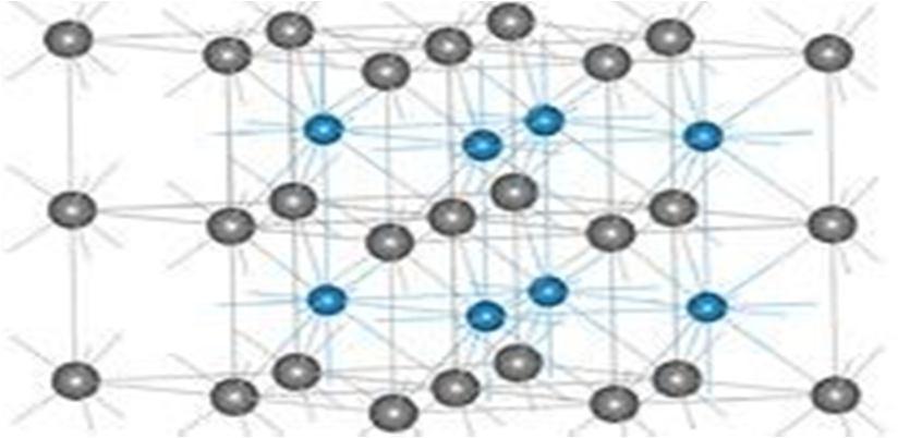
Fig 8.0.1:Coating structure
Selection of process for coating Tungsten Carbide over HSS tool. Here I have chosen Thermal spray technique i.e Plasma coating process for coating Aluminium and Titanium oxide over Cast iron.
ISSN: 2321 9653; IC Value: 45.98; SJ Impact Factor: 7.538

Volume 10 Issue X Oct 2022 Available at www.ijraset.com
Thermal sprayis a surface treatment process that the subtle and dispersed metal or non metallic coating material like wire or powder in a melt or semi molten state, deposits on the substrate surface to form a sort of deposited layer. Thermal spray material is heated to a plastic or molten state and then accelerated. While these particles hitting the substrate surface, they are deformated due to pressure, form layered sheet, and adhere to the substrate surface. They continuously accumulate and eventually form a layered coating. By changing coating materials, different functions can be realized such as erosion resistance, abrasion resistance, heat insulation, ceramic insulation andso on. In engineering and mechanical surface treatment areas, thermal spray technology is the most effective, economic and direct process to enhance the surface functions and parameters. Through the use of thermal spray technique, itcan improve the life of equipment or spare parts, improve the surface performance, as well as reduce production and maintenance costs. Thermal spray features include: abrasion resistance, heat resistant barrier; anti erosion; restore size; gap control; change in electrical conductivity, etc.
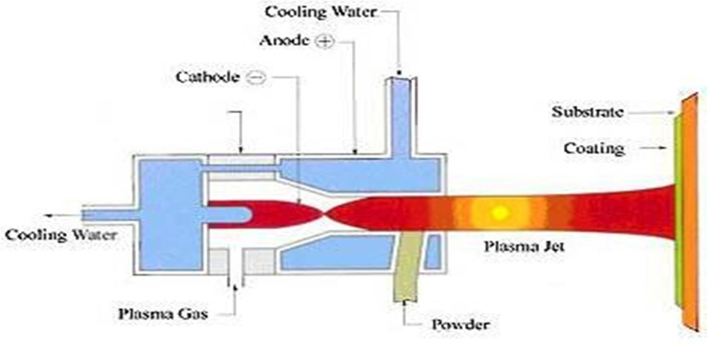
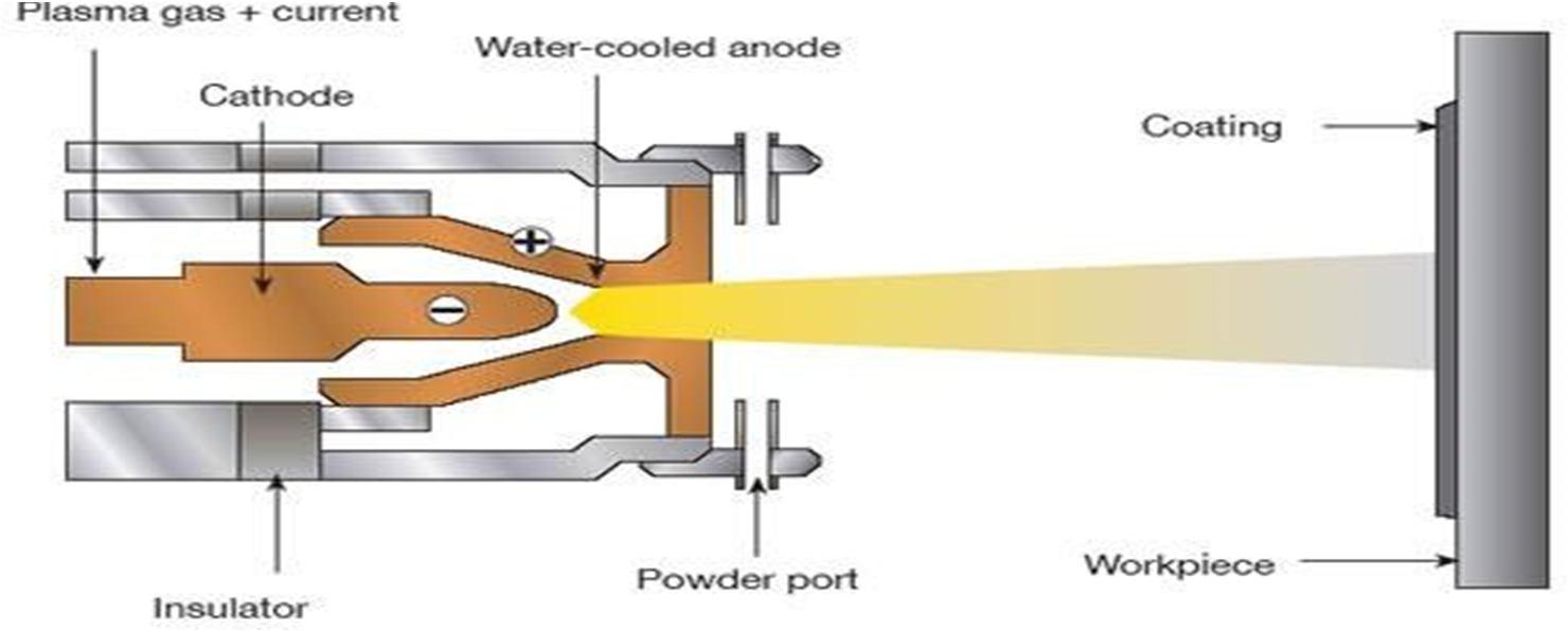
In all thermal spray techniques, plasma spray is the most flexible one as itcan reach a sufficient temperature to melt or heat any material, so the coating material types are almost unlimited.
Plasma spray gun is composed of a small chamber with a cathode (electrode) and an anode (nozzle). Broken down by high intensity arc, the gas through the chamber forms plasma substance, and releases large amount of heat,which can reach the temperature of 6000 16000. When the coating material is high speedily injected into the gas flame, it is melted and impacts on the substrate surface.

ISSN: 2321 9653; IC Value: 45.98; SJ Impact Factor: 7.538 Volume 10 Issue X Oct 2022 Available at www.ijraset.com

We offer Plasma Spraying service using Sulzer Metco equipment comprising of a number of Sulzer Metco units including a 3MB unit feeding a MBN gun and a 7MB unit feeding a 9MB gun is used in this project for the purpose of coating. A wide range of coatings can be applied including ceramics, zirconium, yttrium,chrome carbides & tungsten carbide and used in a wide range of applications including seal diameters, machines spindles & print rollers.
1) Overview of Plasma Coating Process: The plasma coating process is basicallya high frequencyarc, which is ignited between an anode and a tungsten cathode. The gas flowing through between the electrodes (i.e., He, H2, N2 or mixtures) is ionized suchthat a plasma plume several centimeters in length develops. The temperature within the plume can reach as high as 16,000 K. The sprayed material (in powder form) is injected into the plasma plume where it is melted and propelledat high speed to the substrate surface where it rapidly cools and forms the coating.Heat from the hot particles is transferred to the cooler base material. As the particles shrink and solidify, they bond to the roughened base material. Adhesionofthe coating is therefore based on mechanical “hooking”.The plasma spraying process is classed as a cold process and because of this damage and distortion etc. can be avoided to the huge range of substrates we can coat.
2) Pre treatment Process: Surface adhesion is purely mechanical and as such, a solid key is required, free of grease or other contaminants. Therefore the careful cleaning and pre treatment of the surface to be coated is extremely important. Surface roughening usually takes place via grit blasting with dry corundum. In addition, other media, such as chilled iron, steel grit or SiC are used for some applications. All items are grit blasted with sharp abrasive grit to achieve a surface roughness of approximately 100 300µin. Besides the type of grit, other important factors include particle size, particle shape, blast angle, pressure and Suitable substrate materials are those that can withstand blasting procedures to roughen the surface, generally having a surface hardness of about 55 Rockwell or lower. Special processing techniques are required to prepare substrates with ahigher hardness. General Parameters In The Process Roughness of the substrate surface A rough surface provides a good coating adhesion. Cleanliness of the substrates The substrate to be sprayed on must be free from any dirt or grease orany other material that might prevent intimate contact of the splat and the substrate.
3) Cooling Water: For cooling purpose distilled water should be used, whenever possible. ormally a small volume of distilled water is re circulated into the gun and it iscooled by an external water supply from a large tank. Sometime water from alarge xternal tank is pumped directly into the gun.
4) Process Parameters: In plasma spraying one has to deal with a lot of process parameters, which determine the degree of particle melting, adhesion strength and deposition efficiency of the powder. Deposition efficiency is the ratio of amountof powder deposited to the amount fed to the gun.
a) Arc Power: It is the electrical power drawn by the arc. The power isinjected in to the plasma gas, which in turn heats theplasma stream.
b) Plasma Gas: Normally nitrogen or argon doped with about 10% hydrogen or helium is used as a plasma gas. The major constituent of the gas mixture is known as primary gas and the minor is known as the secondary gas.
c) Carrier Gas: Normally the primary gas itself is used as a carrier gas. Theflow rate of the carrier gas is an important factor. A very low flow rate cannot convey the powder effectively to the plasma jet, and if the flow rate is very highthen the powders might escape thehottest region of the jet.

d) Mass Flow Rate of Powder: Ideal mass flow rate for each powder has tobe determined a very high mass flow rate may give rise to an incomplete melting resulting in ahigh amount of porosityin the coating Spraying angle. This parameter is varied to accommodate the shape of the substrate the coating porosity is found to increase as the spraying angle is increased from 30° to 60°. Beyond 60° the porosity level remains unaffected by a further increaseinspraying angle. The spraying angle also affects the adhesive strength of the coating.
THERMAL SPRAY is a generic term for a group of coating processes used to apply metallic or nonmetallic coatings. These processes are grouped intothree major categories: flame spray, electric arc spray, and plasma arc spray. These energy sources are used to heat the coating material (in powder, wire, or rod form) to a molten or semimolten state. The resultant heated particles are accelerated and propelled toward a prepared surface by either process gases or atomization jets. Upon impact, a bond forms with the surface, with subsequent particles causing thickness buildup and forming a lamellar structure. The thin “splats” undergo very high cooling rates, typically in excess of 106 K/s for metals
A major advantage of thermal spray processes is the extremely wide variety of materials that can be used to produce coatings . Virtually any materialthat melts without decomposing can be used. A second major advantage is the ability of most thermal spray processes to apply coatings to substrates without significant heat input.
ISSN: 2321 9653; IC Value: 45.98; SJ Impact Factor: 7.538

Volume 10 Issue X Oct 2022 Available at www.ijraset.com
Thus, materials with very high melting points, such as tungsten, can be applied to finely machined, fully heat treated parts without changing the properties of the part and without excessive thermal distortion of the part. A third advantage is the ability, in most cases, to strip off and recoat worn or damaged coatings without changing part properties or dimensions. A disadvantage is the line of sight nature of these deposition processes. They can only coat what the torch or gun can see. Of course, there are also size limitations. It is impossible to coat small, deep cavities into which a torch orgun will not fit.
Thermal spray coatings may contain varying levels of porosity, depending on the spray process, particle speed and size distribution, and spray distance. Porosity may be beneficial in tribological applications through retention of lubricating oil films. Porosity also is beneficial in coatings onbiomedical implants. Lamellar oxide layers can also lead to lower wear and friction due to the lubricity of some oxides. The porosity of thermal spray coatings is typically <5% by volume. The retention of some unmelted and/or resolidified particles can lead to lower deposit cohesive strengths, especially in the case of “as sprayed” materials with no postdeposition heat treatment or fusion. Other key features of thermal spray deposits are their generally very finegrain structures and columnar orientation. Thermal sprayed metals, for example, have reported grain sizes of <1µm prior to postdeposition heat treatment. Grain structure across an individual splat normally ranges from 10 to 50 µm, with typical grain diameters of 0.25 to 0.5 µm, owing to the high cooling rates achieved (~106 K/s). The tensilestrengths of as sprayed deposits can range from 10 to 60% of those of cast or wrought materials, depending on the spray process used. Spray conditions leading to higher oxide levels and lower deposit densities result in the lowest strengths. Controlled atmosphere spraying leads to ~60% strength, but requires postdeposition heat treatment to achieve near 100% values. Low as sprayed strengths are related somewhat to limited intersplat diffusion and limited grain recrystallization during the rapid solidifi cation characteristic of thermal spray processes. The primary factor limiting adhesion and cohesion is residual stress resulting from rapid solidification of the splats. Accumulated residual stress alsolimits thickness build up Thermal Spray Processes and Techniques Members of the thermal spray family of processes are typically grouped into three major categories: flame spray, electric arc spray, and plasma arc spray, with a number of subsets falling under each category. (Cold spray is a recent addition to the family of thermal spray processes. This process typically uses some modest preheating, but is largely a kinetic energy process. The unique characteristics of cold spray are discussed in the article “Cold Spray Process” in this Handbook.) A brief review of some of the more commercially important thermal spray processes is given below.

Conventional Plasma. The conventional plasma spray process is commonly referred to as air or atmospheric plasma spray (APS).Plasma temperatures in thepowder heating region range from about 6000 to 15,000 C (11,000 to 27,000 F),significantly above the melting point of any known material. To generate the plasma, an inert gas typically argon or an argon hydrogen mixture is superheated by a dc arc. Powder feedstock is introduced via an inert carrier gas and is accelerated toward the workpiece by the plasma jet. Provisions for cooling or regulating the spray rate may be required to maintain substratetemperatures in the 95 to 205 C (200 to 400 F) range. Commercial plasma spray guns operate in the range of 20 to 200 kW. Accordingly, spray rates greatly depend on gun design, plasma gases, powder injection schemes, and materials properties, particularly particle characteristics such as size, distribution, melting point, morphology, and apparent density. Vacuum Plasma. Vacuum plasma spraying (VPS), also commonly referred to as low pressure plasma spraying (LPPS, a registered trademark of Sulzer Metco), uses modified plasma spray torches in a chamber at pressures in the range of 10 to 50 kPa (0.1 to 0.5 atm).
At low pressures the plasma becomes larger in diameter and length, and, through the use of convergent/divergent nozzles, has a higher gas speed. The absence of oxygen and the abil ity to operate with higher substrate temperatures produce denser, more adherent coatings with much lower oxide contents. Kinetic Energy Processes Kinetics has been an important factor in thermal sprayprocessing from the beginning. With the introduction of detonation gun, HVOF,and high energy plasma spraying, the kinetic energy component of thermalspraying became even more important. The latest advance in kinetic spraying is known as “cold spray.” Cold spray is a material deposition process in which coatings are applied by accelerating powdered feedstocks of ductile metals to speeds of 300 to 1200 m/s(985 to 3940 ft/s) using gas dynamic techniques with nitrogen or helium as the process gas. The process is commonly referred to as “cold gas dynamic spraying” because of the relatively low temperatures (0 to 800 C, or 32 to 1470 F) of the expanded gas and particle stream that emanates from the nozzle. Powder feed rates of up to 14 kg/h (30 lb/h) arepossible. Materials for Thermal Spray
ISSN: 2321 9653; IC Value: 45.98; SJ Impact Factor: 7.538

Volume 10 Issue X Oct 2022 Available at www.ijraset.com
Three basic types of deposits can be thermal sprayed:
1) Single phase materials, such as metals, alloys, intermetallics, 2) ceramics, and polymers
3) Composite materials, such as cermets (WC/Co, Cr3C2/NiCr, NiCrAlY/Al2O3 , etc.), reinforced metals, and reinforced polymers
Layered or graded materials, referred to as functionally gradient materials (FGMs) Examples of these, along with their particular advantages and applications, are described below. Single Phase Materials Metals. Most pure metals and metal alloys have been thermal sprayed, including tungsten, molybdenum, rhenium, niobium, superalloys, zinc, aluminum, bronze, mild and stainless steels, Ni Cr alloys, cobalt base Satellites, cobalt/nickel base Tri alloys, and Ni Cr B Si “self fluxing” alloys. Sprayed alloys have advantages due to their similarity to many base metals requiring repair, their high strength, and their corrosion, wear, and/or oxidation resistance. Applications include automotive/diesel engine cylinder coatings; piston rings or valve stems; turbine engine blades, vanes, and combustors; protection of bridges and other corrosionprone infrastructure; petrochemical pumps and valves; and mining andagricultural equipment. Ceramics. Most forms of ceramics can be thermal sprayed, including metallic oxides such as Al2O3 , stabilized ZrO2 , TiO2 , Cr2O3 , and MgO; carbides such as Cr3 C2 , TiC, Mo2C, and SiC (generally in a more ductile supporting metal matrix such as cobalt or NiCr); nitrides such as TiN and Si3 N4 ; and spinels or per ovskites such as mullite and 1 2 3 type superconducting oxides. Sprayed deposits of these materials are used to provide wear resistance (Al2O3 , Cr2 O3 , TiO2 , Cr3 C2 , TiC, Mo2 C, and TiN), thermal protection (Al2O3 , ZrO2 , and MgO), electrical insulation (Al2 O3 , TiO2 , and MgO), and corrosion resistance.

Ceramics are particularly suited to thermal spraying, with plasma spraying being the most suitable process due to its high jet temperatures. Intermetallics such as TiAl, Ti3 Al, Ni3 Al, NiAl, and MoSi2 have all been thermal sprayed. Most intermetallics are very reactive at high temperatures and very sensitive to oxidation; hence, inert atmospheres must be used during plasma spraying. Research has also been conducted on thermal sprayforming/consolidation of bulk intermetallic deposits.Polymers also can be thermal sprayed successfully, provided they are available in particulate form.Thermal spraying of polymers has been practiced commercially since the 1980s, and a growing number of thermoplastic and thermosetting polymers and copolymers have now been sprayed, including urethanes, ethylene vinylalcohols(EVAs), nylon 11, polytetrafluoroethylene (PTFE), ethylene tetrafluoroethylene (ETFE), polyetheretherketone (PEEK), polymethylmethacrylate (PMMA), polyimide, polycarbonate, and copolymers such as polyimide/polyamide, Surlyn(DuPont), and polyvinylidene fluoride (PVDF). Conventional flame spray and HVOF are the most widelyused thermal spray methods for applying polymers.
The impact property of a material is the capacity of the material to absorb and dissipate energies under shock loading. Impact condition may range from the accidental dropping of hand tools to high speed collisions and the response of the structure may range from localized damage to total disintegration of the structure.
The present study is taken up to understand the response of fiber reinforced plastic laminated plates under low energy, and low velocity impacts to simulate the case of a cover plate, in an automobile engineof wing of an aircraft subjected to impact loading. The commercially available impact testing machines are having the sensors provided to the drop weight which is susceptible foe sensor failure would give the impact force only.
Furtherthese sensors would require sensitivity to sense the impact force.
High strain rate or impact loads may be expected in many engineering applications of composite materials. The suitability of a composite for such application is therefore, determined not only by usual parameter, but also by impact or energy absorbing properties.
Frequently, an attempt to improve the strength properties results in a deterioration of the impact properties. Thus it is important to have a good understanding of impact behaviour of composite for both safe and efficient design of structure and to develop new composite having well impact properties as well as good tensile properties.
The extent of damage depend not only on the intensity of impact and material behaviour, but also on the shape and the dimension of the bodies in the region of impact, their hardness and wave propagation properties. The different forms of damages that may occur are yielding, delamination, cracking, spalling and deformation. The elastic indentation takes place at low velocity impacts.Yeilding or cracking depends on whether the material is ductile or brittle.penertation is the entrance of one body into without completing its passage through the bod.perforation means complete piercing through the target.
Impact load may arise in practical situations from variety of sources witha wide range of velocities, duration of contact, momentum and energy release.
ISSN: 2321 9653; IC Value: 45.98; SJ Impact Factor: 7.538

Volume 10 Issue X Oct 2022 Available at www.ijraset.com
The stress distribution, amplitude of vibration, pattern of wave propagation and the nature of load damages depend on parameter like:
a) Velocity of the Impactor b) Duration of the Impact c) Mass and shape of the impactor d) Target
e) The distribution and intensity of force developed at the pointof impact.
A.

CATIA is one of the world’s leading CAD/CAM/CAE package. Being asolid modeling tool, it not only unites 3D parametric features with 2D tools, but also addresses every design through manufacturing process.
CATIA Computer Aided Dimensional Interactive Application.
CATIA, developed by Dassult systems, france, is a completely re engineered, next generation family of CAD/CAM/CAE software solution.
CATIA serves the basic design task by providing different workbenches, some of the workbenches available in this package are
1) Part design workbench
2) Assembly design workbench
3) Drafting workbench
4) Wireframe and surface design workbench
5) Generative shape design workbench
6) DMU kinematics
7) Manufacturing
8) Mold design
The part workbench is a parametric and feature based environment, in which we can create solid models. In the part design workbench, we are provided with tool those convert sketches into other features are called the sketch based features.
The assembly design workbench is used to assemble the part by using assembly constraints. There are two type of assembly design, 1) Bottom up
2) Top down
In bottom up assembly, the parts are created in part workbench and assembledin assembly workbench. In the top down workbench assembly, the parts are created in assemblyworkbench itself.
The wire frame and surface design workbench is also parametric and feature based environment. The tools available in this workbench are similar to those in the part workbench, with the only difference that the tool in thisenvironment are used to create basic and advance surfaces
The drafting workbench is used for the documentation of the parts or the assemblies created in the form of drafting. There are two types of drafting techniques:
1) Generative drafting
2) Interactive drafting
The generative drafting technique is used to automatically generate the drawing views of parts and assemblies.In interactive drafting, we need to create the drawing byinteractive with the sketcher to generate the views.
ISSN: 2321 9653; IC Value: 45.98; SJ Impact Factor: 7.538

Volume 10 Issue X Oct 2022 Available at www.ijraset.com

This workbench deals with the relative motion of the parts.DMU kinematics simulator is an independent CAD product dedicated to simulating assembly motions. It addresses the design review environment of digital mock ups (DMU) and can handle a wide range of products from customer goods to very large automotive or aerospace projects as well as plants, ships and heavy machinery.
Composite materials have been used in structures for a long time. In recent times composite parts have been used extensively in aircraft structures, automobiles, sporting goods, and many consumer products.
Composite materials are those containing more than one bonded material,each with different structural properties. The main advantage of composite materials is the potential for a high ratio of stiffness to weight. Composites used for typical engineering applications are advanced fiber or laminated composites, such as fiberglass, glass epoxy, graphite epoxy, and boron epoxy. ANSYS allows us to model composite materials with specialized elements called layered elements. Once we build our model using these elements, we can do any structural analysis (including nonlinearities such as large deflectionand stress stiffening).
Composites are somewhat more difficult to model than an isotropic material such as iron or steel. We need to take special care in defining the properties and orientations of the various layers since each layer may have different orthotropic material properties. In this section, we will concentrate on the following aspects of building a composite model:
1) Choosing the proper element type
2) Defining the layered configuration
3) Specifying failure criteria
4) Following modelingand post processingguidelines
The following element types are available to model layered composite materials: SHELL99, SHELL91, SHELL181, SOLID46, and SOLID191.
Which element we choose depends on the application, the type of results that need to be calculated, and so on. Check the individual element descriptions to determine if a specific element can be used in our ANSYS product. All layeredelements allow failure criterion calculations.
1) SHELL99 Linear Layered Structural Shell Element: SHELL99 is an 8 node, 3 D shell element with six degrees of freedom at each node. It is designed to model thin to moderately thick plate and shell structures with a side to thickness ratio of roughly 10 or greater. For structureswith smaller ratios, we may consider using SOLID46. The SHELL99 element allows a total of 250 uniform thickness layers. Alternately, the element allows 125 layers with thicknesses that may vary bilinearly over the area of the layer. If more than 250 layers are required, we can input our own material matrix. It also has an option to offset the nodes to the top or bottom surface.
2) SHELL91 Nonlinear Layered Structural Shell Element: SHELL91 is similar to SHELL99 except that it allows only up to 100 layers and does not allow us to input a material property matrix. However, SHELL91 supports plasticity, large strain behavior and a special sandwich option, whereas SHELL99 does not. SHELL91 is also more robust for large deflection behaviour.
3) SHELL181 Finite Strain Shell: SHELL181 is a 4 node 3 D shell element with 6 degrees of freedom at each node. The element has full nonlinear capabilities including large strain and allows 255 layers. The layer information is input using the section commands rather than real constants. Failure criteria are available using theFC commands.
4) SOLID46 3 D Layered Structural Solid Element: SOLID46 is a layered version of the 8 node, 3 D solid element, SOLID45, with three degrees of freedom per node (UX, UY, UZ). It is designed to model thick layered shells or layered solids and allows up to 250 uniform thickness layers per element. Alternately, the element allows 125 layers with thicknesses that may vary bilinearly over the area of the layer. An advantage with this element type is that you can stack several elements to model more than 250 layers to allow through the thickness deformation slope discontinuities. The user input constitutive matrix option is also available. SOLID46 adjusts the material properties in the transverse direction permitting constant stresses in the transverse direction. In comparison to the 8 nodeshells, SOLID46 is a lower order element and finer meshes may be requiredfor shell applications to provide the same accuracy as SHELL91 or SHELL99.
ISSN: 2321 9653; IC Value: 45.98; SJ Impact Factor: 7.538 Volume 10 Issue X Oct 2022 Available at www.ijraset.com

5) SOLID191 Layered Structural Solid Element: SOLID191 is a layered version of the 20 node 3 D solid element SOLID95, with three degrees of freedom per node (UX, UY, UZ). It is designed to model thick layered shells or layered solids and allows up to 100 layers per element. As with SOLID46, SOLID191 can be stacked to model through the thickness discontinuities. SOLID191 has an option to adjust the material properties in the transverse direction permitting constant stresses in the transverse direction. In spite of its name, the element does not support nonlinear materials or large deflections. In addition to the layered elements mentioned above, other composite element capabilities exist in ANSYS, but will not be considered further in the chapter:
a) SOLID95, the 20 node structural solid element, with KEYOPT(1) = 1functions similarly to a single layered
b) SOLID191 including the use of an orientation angle and failurecriterion. It allows nonlinear materials and large deflections.
c) SHELL63, the 4 node shell element, can be used for rough, approximate studies of sandwich shell models. A typical application would be a polymer between two metal plates,where the bending stiffness of the polymer would be small relative to the bending stiffness of the metal plates. The bending stiffness can be adjusted by the real constant RMI to represent the bending stiffness due to the metalplates, and distances from the middle surface to extreme fibers (real constants CTOP, CBOT) can be used to obtain output stress estimates on the outer surfaces of the sandwich shell. It is not used as frequently as SHELL91,SHELL99, or SHELL181, and will not be considered for anything other than sandwich structures in this section.

d) SOLID65, the 3 D Reinforced Concrete Solid Element, models an isotropic medium with optional reinforcing in 3 different user defined orientations.
e) BEAM188 and BEAM189, the 3 D finite strain beam elements, canhave their sections built up with multiple materials.
SOLID45 is used for the 3 D modeling of solid structures. The element isdefined by eight nodes having three degrees of freedom at each node: translations in thenodal x, y, and z directions. The element has plasticity, creep, swelling, stress stiffening, large deflection,and large strain capabilities.

Fig 9.1:Solid elemet structure


ISSN: 2321 9653; IC Value: 45.98; SJ Impact Factor: 7.538 Volume 10 Issue X Oct 2022 Available at www.ijraset.com




ISSN: 2321 9653; IC Value: 45.98; SJ Impact Factor: 7.538 Volume 10 Issue X Oct 2022 Available at www.ijraset.com


ISSN: 2321 9653; IC Value: 45.98; SJ Impact Factor: 7.538 Volume 10 Issue X Oct 2022 Available at www.ijraset.com






ISSN: 2321 9653; IC Value: 45.98; SJ Impact Factor: 7.538 Volume 10 Issue X Oct 2022 Available at www.ijraset.com



ISSN: 2321 9653; IC Value: 45.98; SJ Impact Factor: 7.538 Volume 10 Issue X Oct 2022 Available at www.ijraset.com

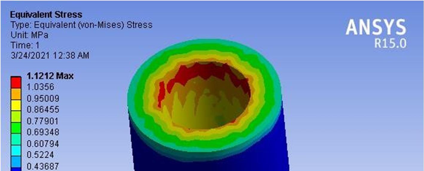
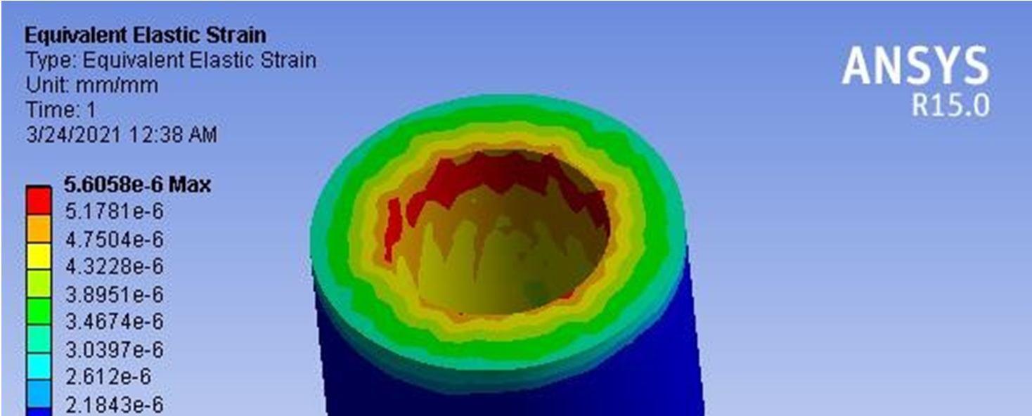

Temperature test of Zirconia coating on steel
Temperature test of Zirconia coating on steel
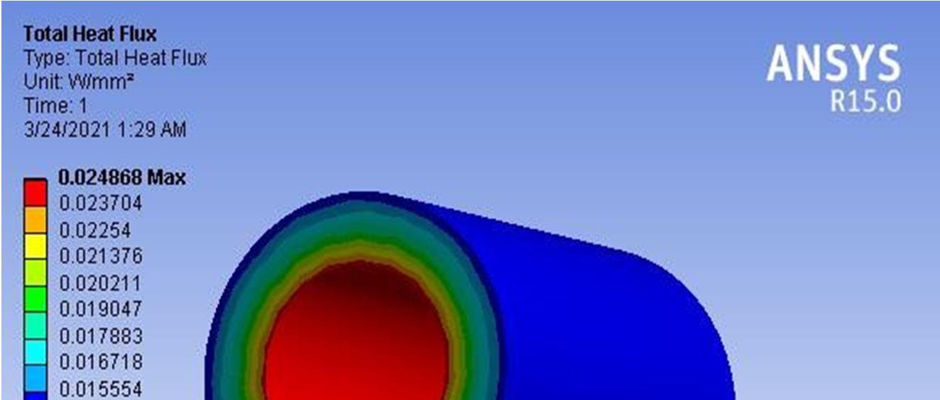
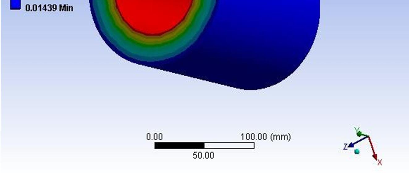
Fig 10.16
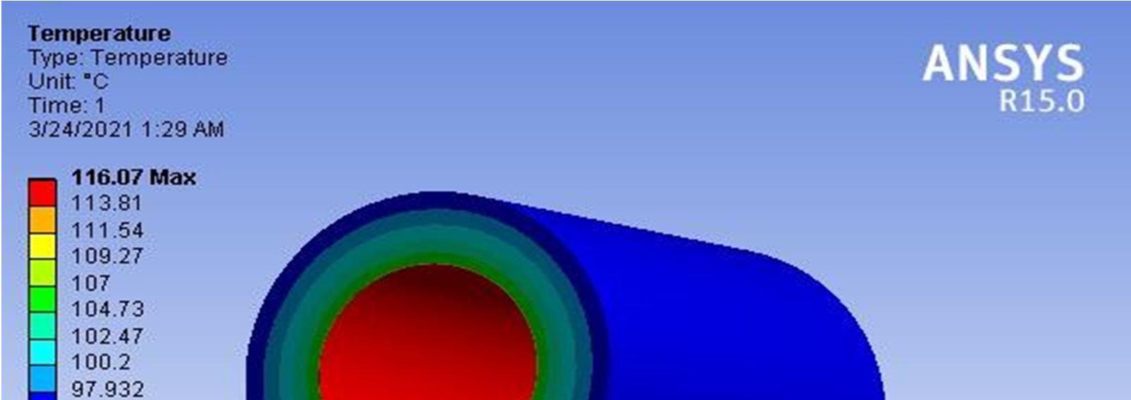
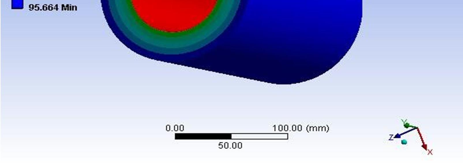
Fig 10.17


ISSN: 2321 9653; IC Value: 45.98; SJ Impact Factor: 7.538 Volume 10 Issue X Oct 2022 Available at www.ijraset.com
ISSN: 2321 9653; IC Value: 45.98; SJ Impact Factor: 7.538 Volume 10 Issue X Oct 2022 Available at www.ijraset.com

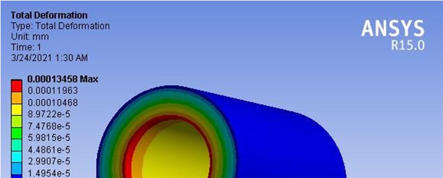
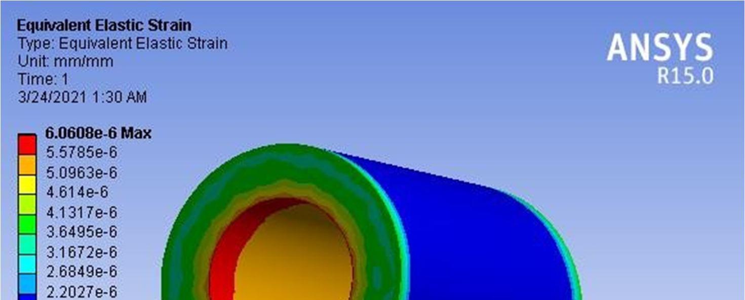
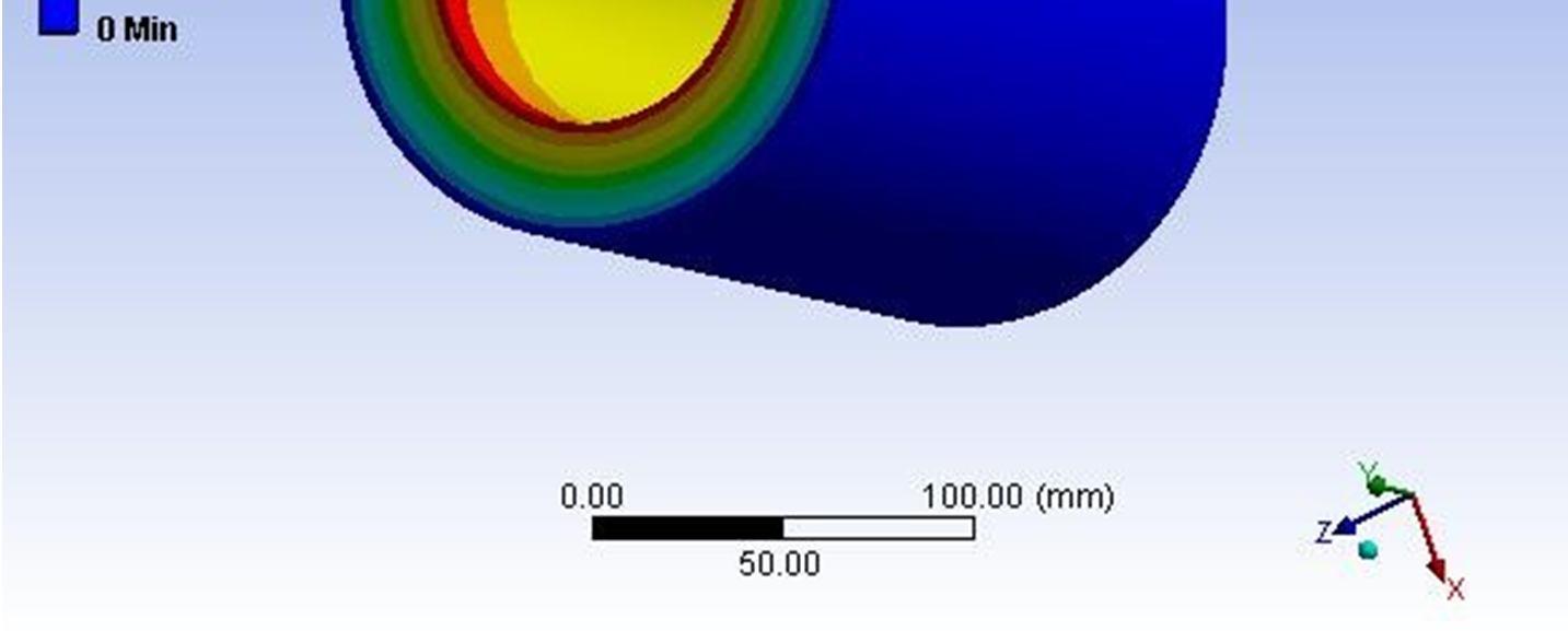
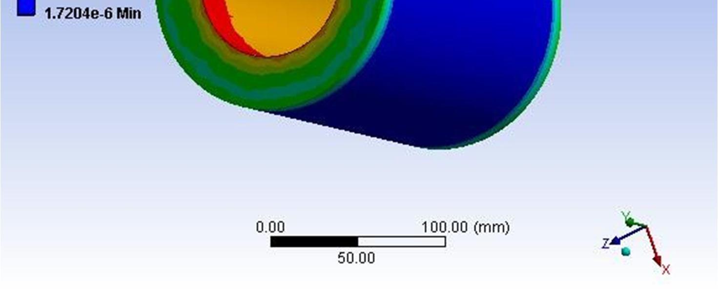

Fig 10.21


ISSN: 2321 9653; IC Value: 45.98; SJ Impact Factor: 7.538 Volume 10 Issue X Oct 2022 Available at www.ijraset.com
ISSN: 2321 9653; IC Value: 45.98; SJ Impact Factor: 7.538 Volume 10 Issue X Oct 2022 Available at www.ijraset.com



ISSN: 2321 9653; IC Value: 45.98; SJ Impact Factor: 7.538 Volume 10 Issue X Oct 2022 Available at www.ijraset.com



ISSN: 2321 9653; IC Value: 45.98; SJ Impact Factor: 7.538 Volume 10 Issue X Oct 2022 Available at www.ijraset.com



ISSN: 2321 9653; IC Value: 45.98; SJ Impact Factor: 7.538 Volume 10 Issue X Oct 2022 Available at www.ijraset.com




ISSN: 2321 9653; IC Value: 45.98; SJ Impact Factor: 7.538 Volume 10 Issue X Oct 2022 Available at www.ijraset.com




ISSN: 2321 9653; IC Value: 45.98; SJ Impact Factor: 7.538 Volume 10 Issue X Oct 2022 Available at www.ijraset.com

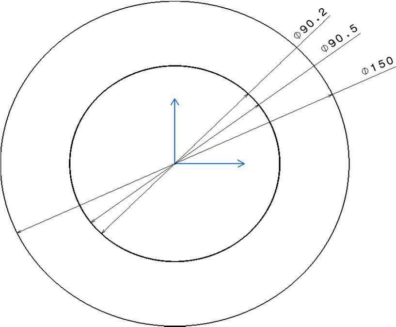
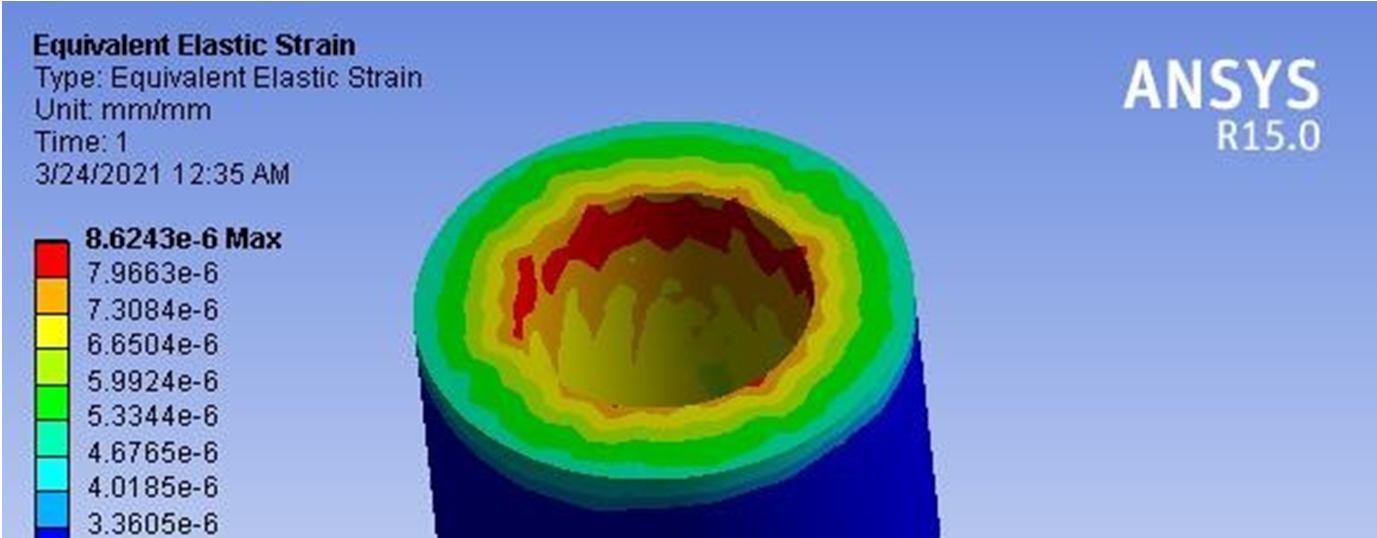
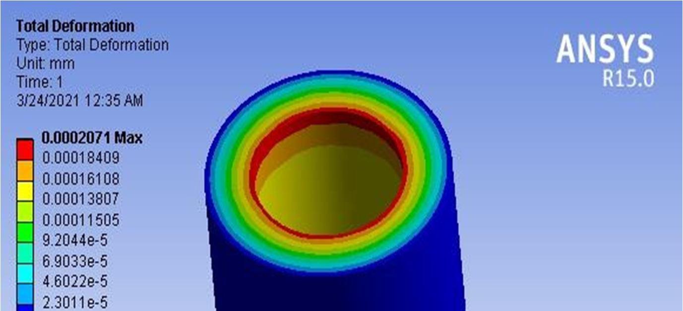
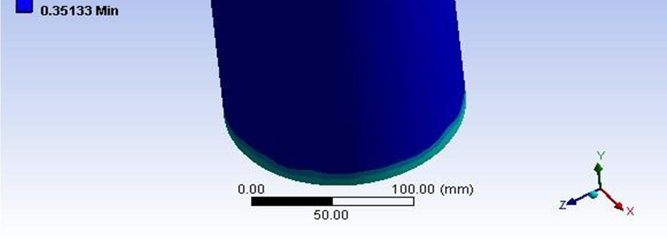
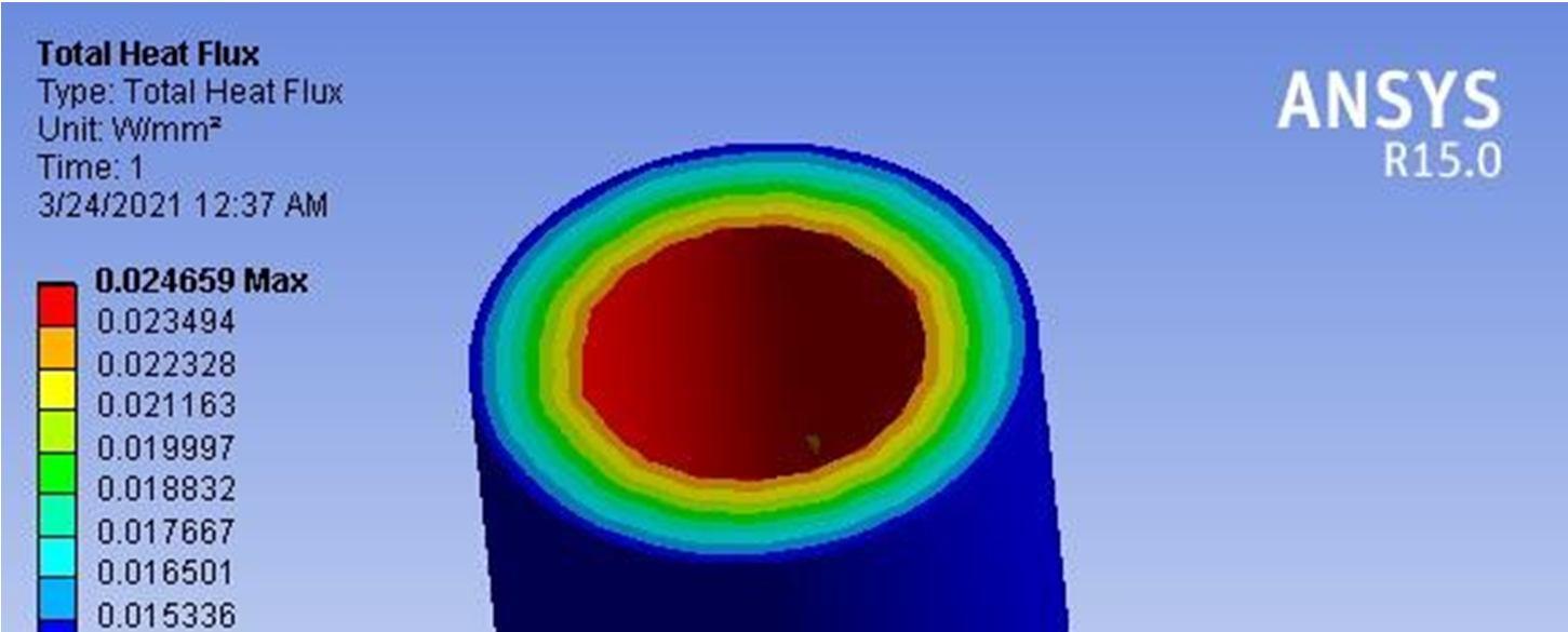
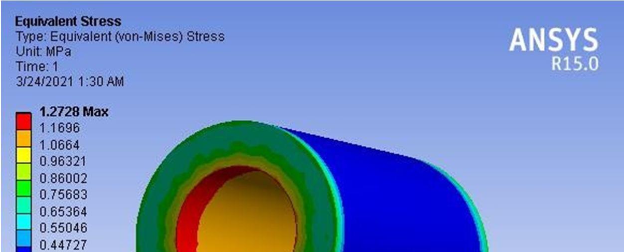
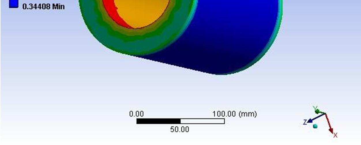
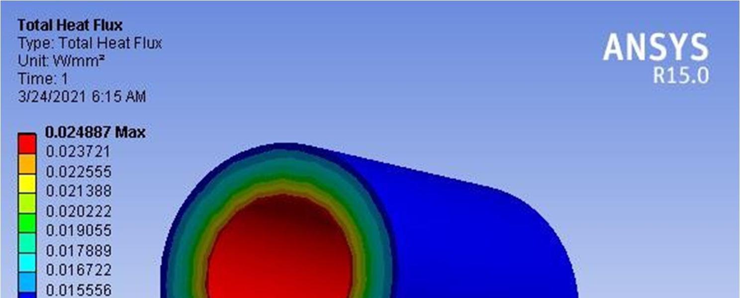
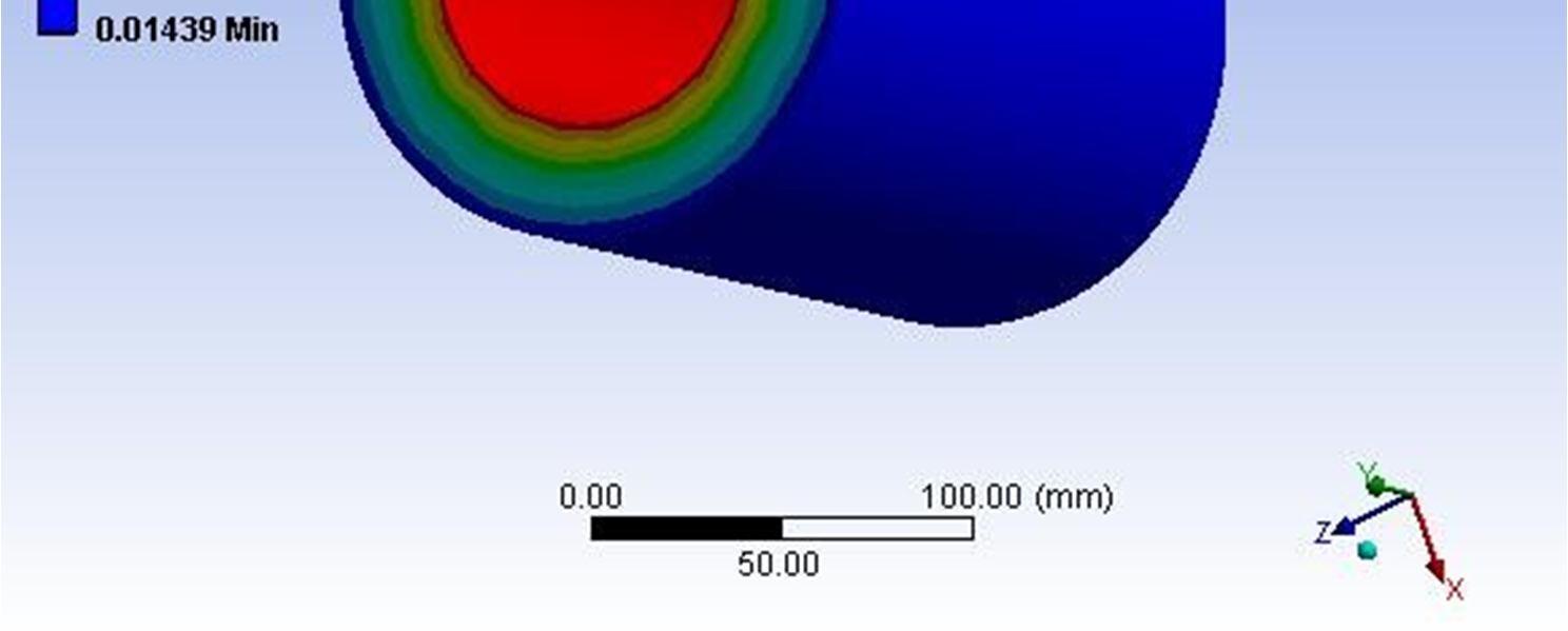
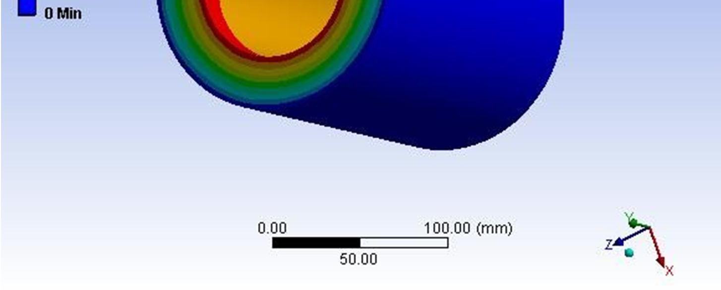
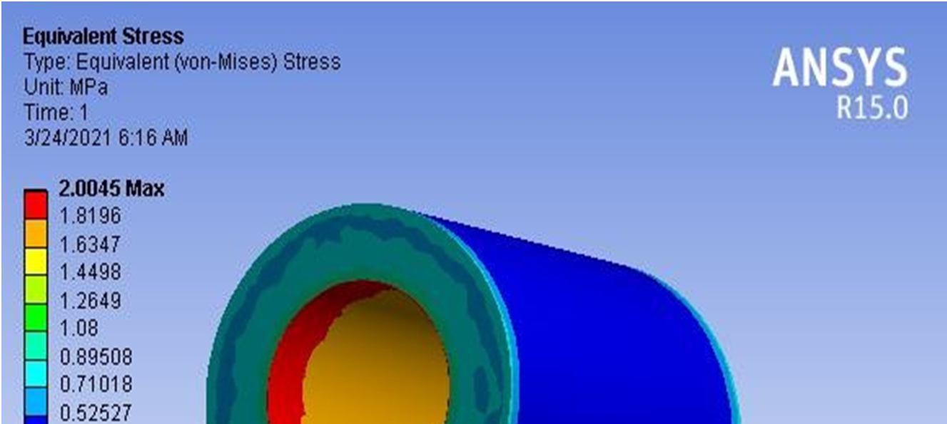
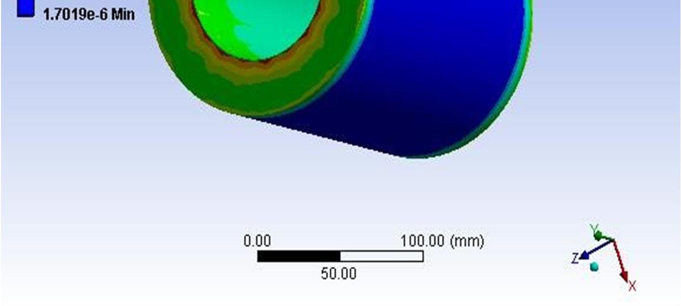
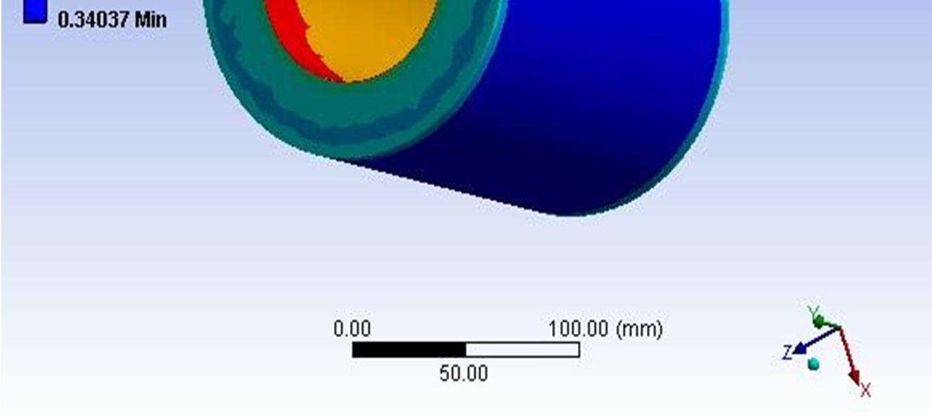
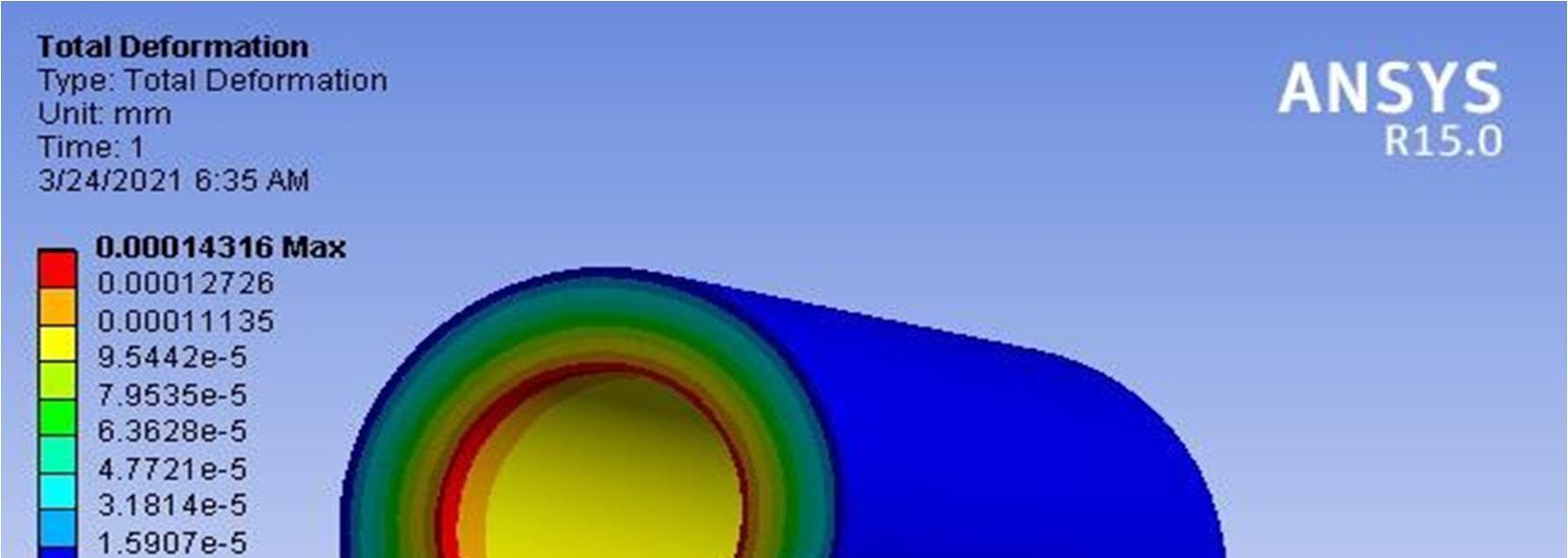
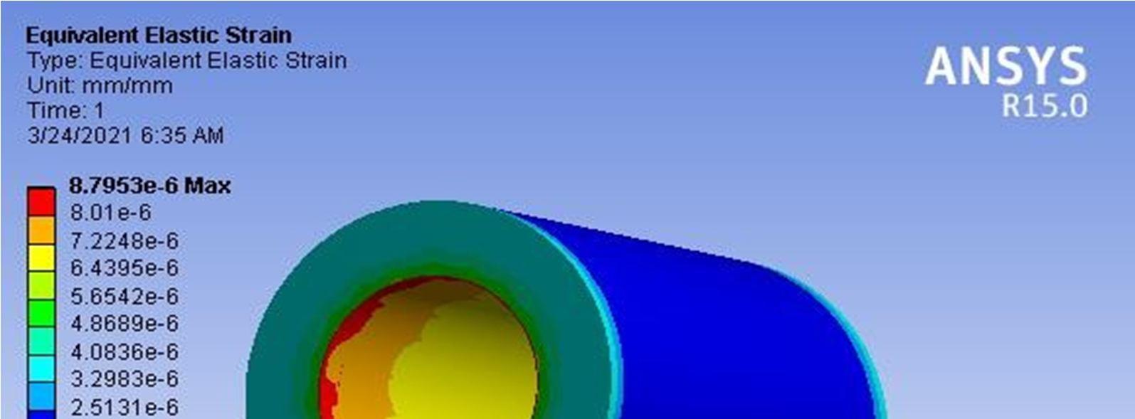
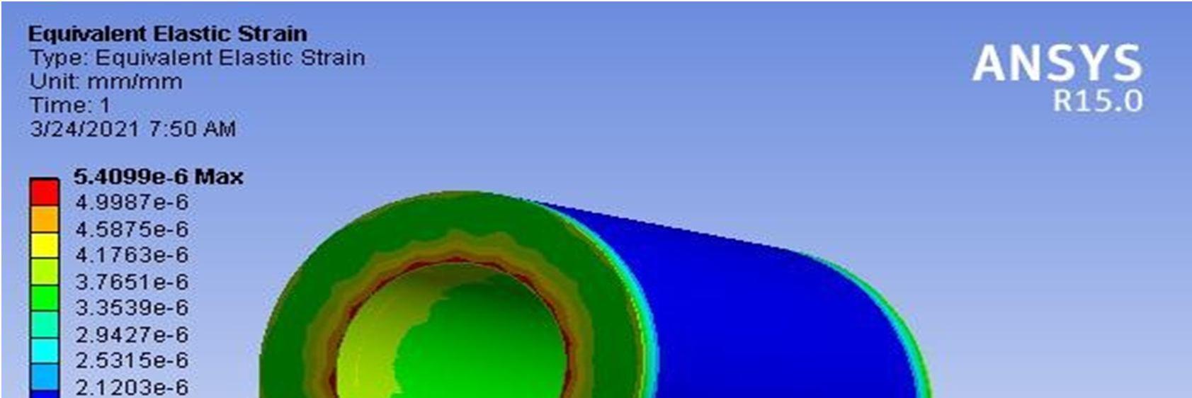
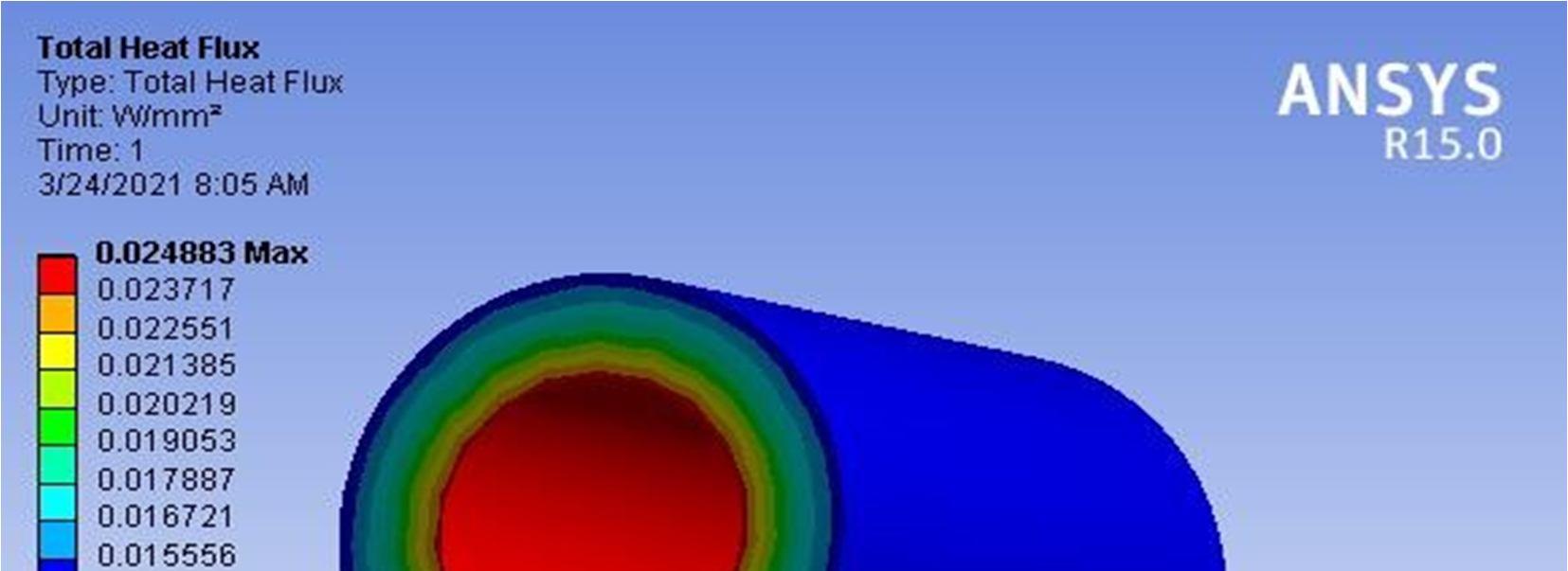
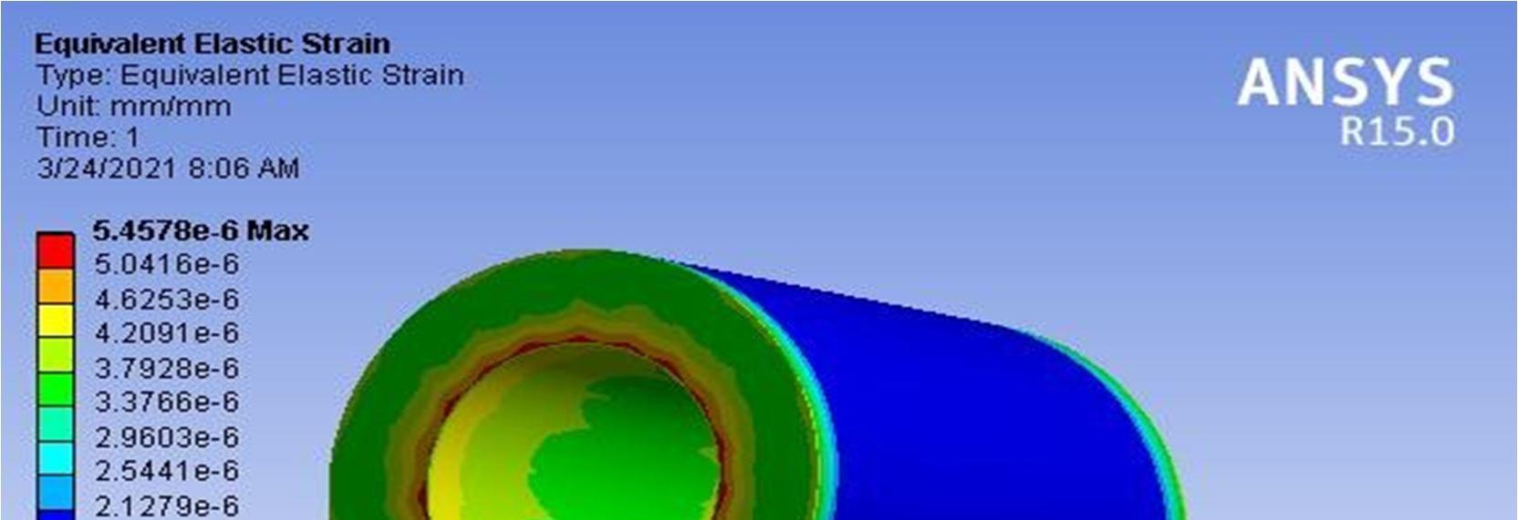
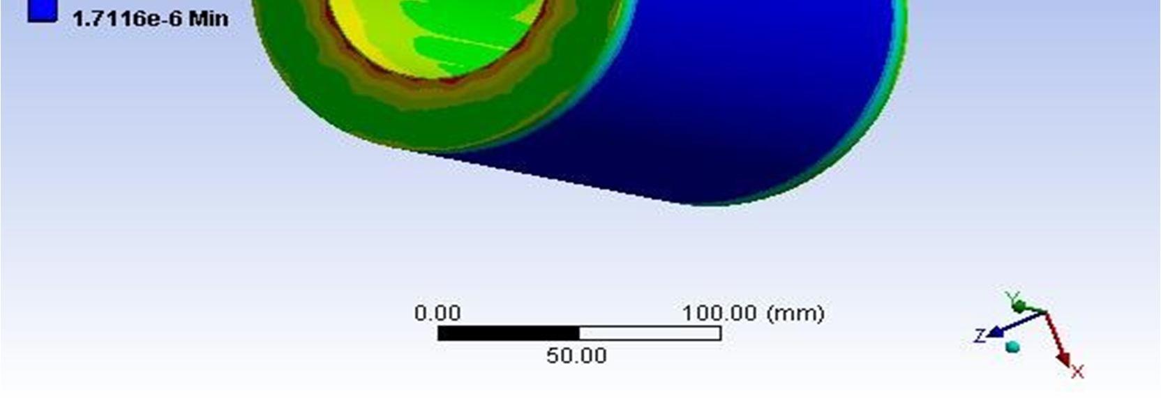
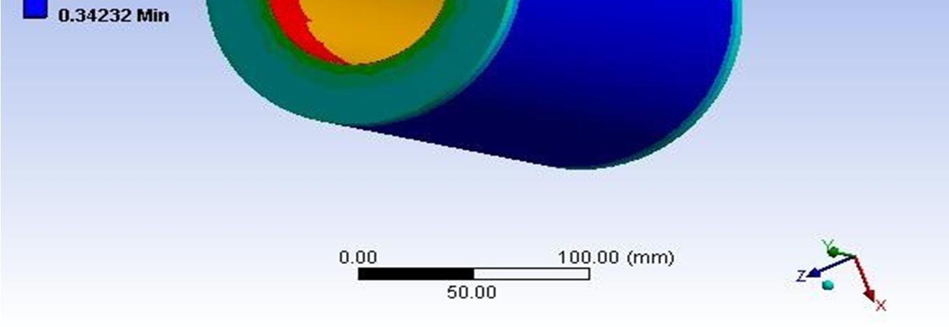
CASTIRON 111.25 0.02465 0.0002071 8.6243 1.1212 STEEL 106.84 0.02465 0.00013461 5.6058 1.1212 ZIRCONIA COATING ON STEEL 116.07 0.02486 0.00013458 6.0608 1.2728 ALUMINA COATING ON STEEL 107.45 0.02488 0.00012299 5.3249 2.0045
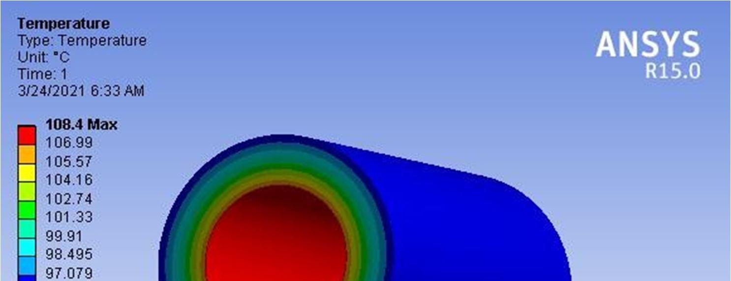
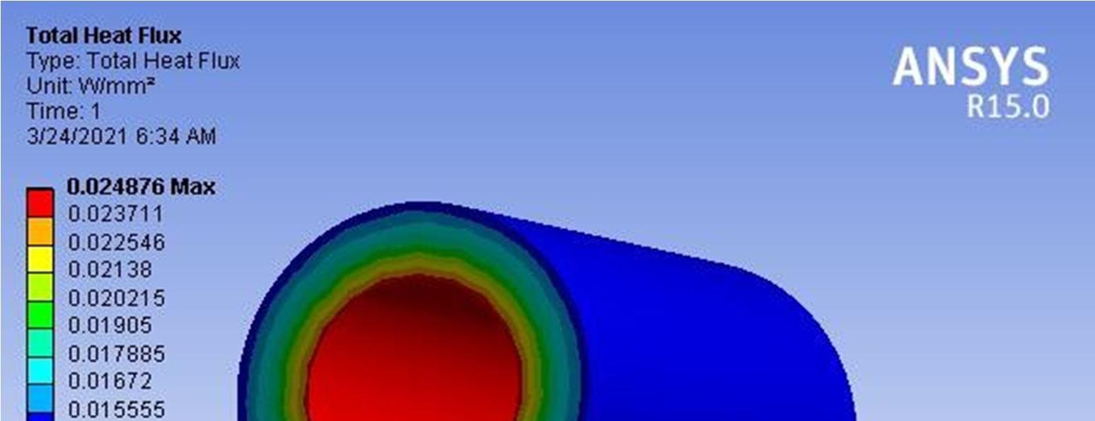
TITANIA COATING ON STEEL 108.4 0.02487 0.00014316 8.7953 1.1866
ALUMINA60+ ZIRCONIA40 COATING ON STEEL
107.82 0.02488 0.00012647 5.4099 1.7143 ALUMINA 60+TITANIA 40 COAATINGON STEEL
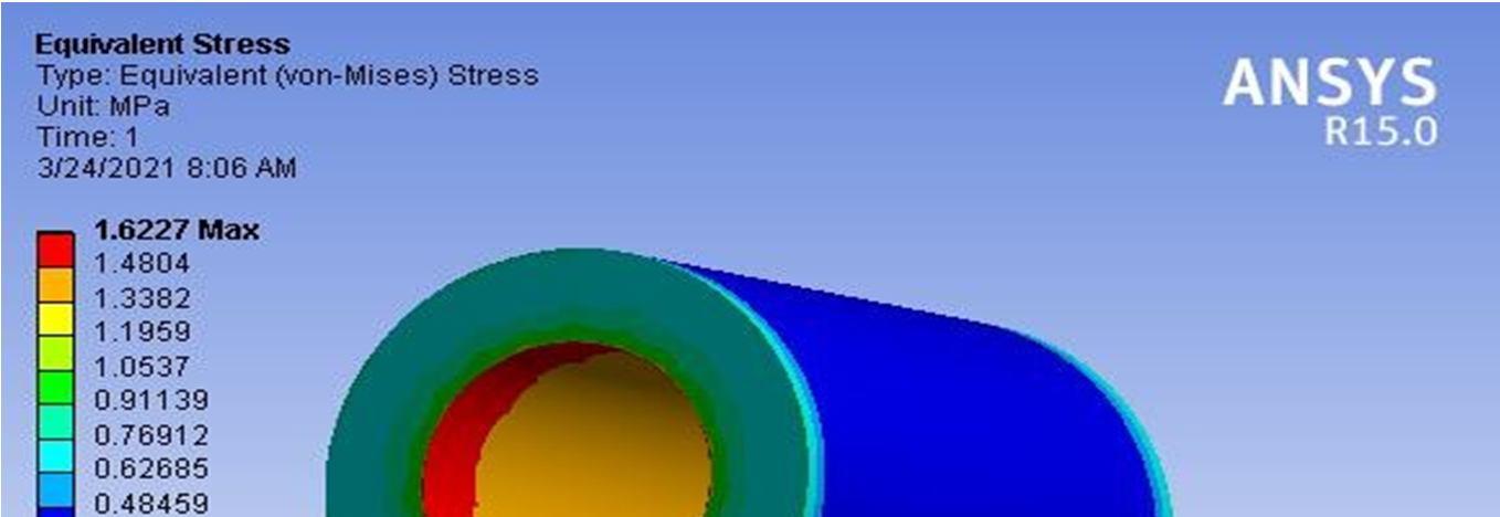

107.65 0.02488 0.00012785 5.4578 1.6227
ISSN: 2321 9653; IC Value: 45.98; SJ Impact Factor: 7.538
Volume 10 Issue X Oct 2022 Available at www.ijraset.com
From the obtained numerical investigations, coating on cylinder liner by thermal spray coatings were used investigated. The Zirconia coated liner was provided the most dramatic improvements over existing cast iron liner, in engine component applications where failure mechanisms that are driven by high temperatures and chemical diffusion are important for life (with the proof of table from ansys).
To conduct performance and emission of characteristic of the diesel engine with coated piston. To conduct performance and wear test on coated inletand valves to improve life. To conduct thermal barrier coating on piston head and piston rings to extend material life and wear.
[1] Ekrem Buyukkaya (2020), “Thermal Analysis of functionally graded coating AlSi alloy and steel pistons”, Surface and coatings technology
[2] Reinhold H. Dauskardt(2019), “THERMAL BARRIER COATINGS”
[3] M. Foy, M. Marchese, G. Jacucci(2019), Engineering plasma spray films by knowledge based simulations proceedings of IFIP conference on, in: Arthur B. Baskin, et al., (Eds.), Cooperative Knowledge Processing for Engineering Design, Kluwer Academic Publishers, The Netherlands, p. 289.

[4] J.S. Lee, T. Matsubara, T. Sei, T. Tsuchiya, J. Mater(2015), Preparation and properties of Y2O3 doped ZrO2 thin films by the sol gel process, Surface Coating Technology
[5] J.N.Reddy, “An introduction to finite element analysis”.
[6] Zhang T, Xu L, Xiong W, et al. Experimental research on the thermal contactresistance between Cu Cu in vacuum and lowtemperature. Cryogenics, 1999.
[7] ANSYS manual guide.
[8] www.sciencedirect.com

[9] www.azom.com “Functionally Graded Materials (FGM) and Their ProductionMethods”.
[10] D. Robinson, R. Palaninathan (2001).Thermal analysis of piston using 3Dfinite element method. Elsevier B.V
[11] A.R.Bhagat, Y.M.Jibhakate.Thermal Analysis of I.C Engine Piston UsingFinite element method(IJMER)Vol.2,Issue4,July Aug2012.
