ISSN: 2321 9653; IC Value: 45.98; SJ Impact Factor: 7.538
Volume 10 Issue X Oct 2022 Available at www.ijraset.com


ISSN: 2321 9653; IC Value: 45.98; SJ Impact Factor: 7.538
Volume 10 Issue X Oct 2022 Available at www.ijraset.com
Mr. Ankush Vilas Chandanshive1 , Prof. D. H. Nimbalkar2
1PG Student, Department of Mechanical Engineering, Terna College Of Engineering Osmanabad
2Professor, Department of Mechanical Engineering, Terna College Of Engineering Osmanabad
Abstract: To design the spur gear to study the weight reduction and stress distribution for cast steel and composite materials. Gearing is one of the most critical components in a mechanical power transmission system, and in most industrial rotating machinery. It is possible that gears will predominate as the most effective means of transmitting power in future machines due to their high degree of reliability and compactness. In addition, the rapid shift in the industry from heavy industries such as shipbuilding to industries such as automobile manufacture and office automation tools will necessitate a refined application of gear technology. To design the spur gear model using designs software. To study the impact analysis for cast steel and composite materials. To study the torque loading for cast steel and composite materials. Finally, comparing and analysing of the composite gear with existing cast steel gear is to be done.
Keywords: Gear, Composite Material, Ansys, fibre, Epoxy.
Spur gears or straight cut gears are the simplest type of gear. They consist of a cylinder or disk with teeth projecting radially. Though the teeth are not straight sided (but usually of special form to achieve a constant drive ratio, mainly involute but less commonly cycloidal), the edge of each tooth is straight and aligned parallel to the axis of rotation. These gears mesh together correctly only if fitted to parallel shafts. No axial thrust is created by the tooth loads. Spur gears are excellent at moderate speeds but tend to be noisy at high speeds. Spur gear teeth are manufactured by either involute profile or cycloidal profile. Most of the gears are manufactured by involute profile with 20° pressure angle. When two gears are in mesh at one instant there is a chance to mate involute portion with non involute portion of mating gear. This phenomenon is known as "interference" and occurs when the number of teeth on the smaller of the two meshing gears is less than a required minimum. To avoid interference we can have undercutting, but this is not a suitable solution as undercutting leads to weakening of tooth at its base. In this situation Corrected gears are used. In corrected gears Cutter rack is shifted upwards or downwards.
A gear or cogwheel is a rotating machine part having cut teeth or, in the case of a cogwheel, inserted teeth (called cogs), which mesh with another toothed part to transmit torque. Geared devices can change the speed, torque, and direction of a power source. Gears almost always produce a change in torque, creating a mechanical advantage, through their gear ratio, and thus may be considered a simple machine. The teeth on the two meshing gears all have the same shape.[1] Two or more meshing gears, working in a sequence, are called a gear train or a transmission. A gear can mesh with a linear toothed part, called a rack, producing translation instead of rotation
1) The objective of the project is to reduce the stress distribution, deformation and weight of spur gear by using composite materials in the application of gear box.

2) Stress analysis such as prediction of contact stress and bending stress.
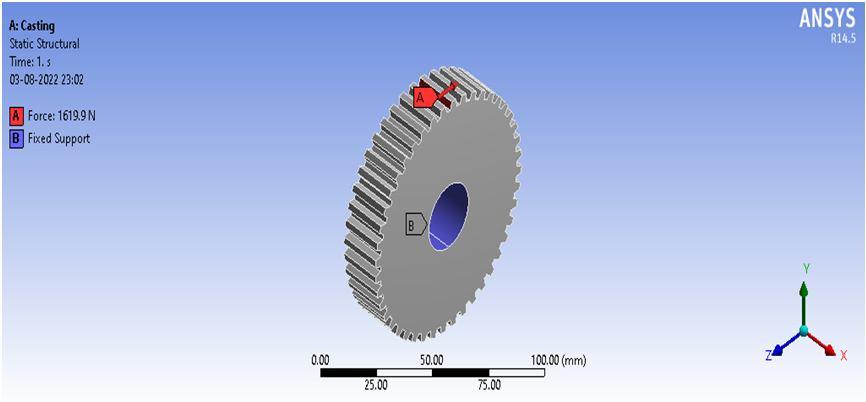
3) The designed composite spur gear is compared with the existing gear materials, such as structural steel, Gray cast iron and aluminium alloy. The tool which is used to analyse the different spur gear materials is ANSYS.

4) Prediction of transmission efficiency
5) The final outputs of these analyses for all the materials are to be compared. From this comparison, the stress induced, deformation and weight for composite spur gear materials are to be less than that of the general spur gear materials.
ISSN: 2321 9653; IC Value: 45.98; SJ Impact Factor: 7.538 Volume 10 Issue X Oct 2022 Available at www.ijraset.com


D. Silicon Nitride Result

& Engineering Technology (IJRASET
ISSN: 2321 9653; IC Value: 45.98; SJ Impact Factor: 7.538 Volume 10 Issue X Oct 2022 Available at www.ijraset.com
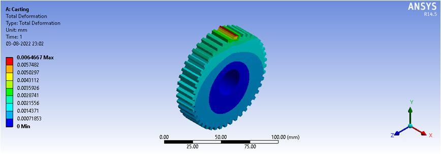
Fig 6. Total deformation in silicon nitride gear due to applied boundary condition.
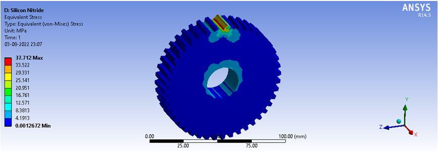
Fig 5. Stress generated in silicon nitride gear due to applied boundary condition.
Sr. No. Material Stress (MPa) Deformation (mm) 1 Cast Iron 40.005 0.006 2 Glass Fiber 43.52 0.11 3 Carbon Fiber 43.01 0.0889 4 Silicon Nitride 37.71 2.16e 9
Table1.Result of all material by using ANSYS software
Weight of Gear
Sr. No. Material Weight (Kg) 1 Cast Iron 0.8299 2 Glass Fiber 0.230 3 Carbon Fiber 0.184 4 Silicon Nitride 0.381
Table 2. Weight of all materials gears
On the basis of that study, the analysis of four material gears in the application of gear box which is used in Lathe machine So, we consider similar boundary condition for all analysis. From this analysis we got the stress values for Silicon Nitride materials is less as compared to the cast steel spur gear. So, from these analysis results, we conclude that, the stress induced, deformation and weight of the Silicon Nitride spur gear is less as compared to the cast steel spur gear. Hence silicon nitride is best as per our application with minimum weight and high strength.


[1] Siva Prasad, Syed AltafHussain, V. Pandurangadu, K.PalaniKumar, ― Modeling and Analysis of Spur Gear for Sugarcane Juice Machine under Static Load Condition by Using FEA, International Journal of Modern Engineering Research (IJMER), Vol.2, Issue.4, July Aug 2012 pp 2862 2866, ISSN: 2249 6645.
[2] K. Mao, ―A new approach for polymer composite gear design, Mechanical Engineering, School of Engineering and Design, Brunel University, Uxbridge, Middlesex UB8 3PH, UK, accepted 14 June 2006.
[3] K. Mao, ―A numerical method for polymer composite gear flash temperature prediction, Mechanical Engineering, School of Engineering and Design Brunel University, Uxbridge, Middlesex UB8 3PH, UK, accepted 8 January 2007.
[4] S. Kirupasankar, C. Gurunathan, R. Gnanamoorthy, ―Transmission efficiency of polyamide nanocomposite spur gears, Indian Institute of Information Technology, Design and Manufacturing (IIITD&M) Kancheepuram, Melakottaiyur, Chennai 600 048, India, Materials and Design 39 (2012) 338 343.


ISSN: 2321 9653; IC Value: 45.98; SJ Impact Factor: 7.538 Volume 10 Issue X Oct 2022 Available at www.ijraset.com
[5] N.A. Wright1, S.N. Kukureka, ―Wear testing and measurement techniquesforpolymer composite gears, School of Metallurgy and Materials, The University of Birmingham, Edgbaston, Birmingham B15 2TT, UK, Wear 251 (2001) 1567 1578.
[6] Sushil Kumar T, Upendra Kumar J 2012 Stress analysis of mating involute spur gear teeth International Journal of Engineering Research and Technology 1 1 12
[7] Vivek K, Ashish M, Preman T.R.J 2013 Modeling and Finite Element Analysis of Spur Gear. International Journal of Current Engineering and Technology 3 2104 2107
[8] Mahebub V, Kevin V 2014 Comparative finite element analysis of metallic and non metallic spur gear. IOSR Journal of Mechanical and Civil Engineering 11 136 145
[9] Pawar P.B, Abhay A.U 2014 Development of aluminium based silicon carbide particulate metal matrix composite for spur gear Elsevier Procedia Materials Science 6 1150 1156
[10] Sajad H.D, Vivek A, Mohammad J.K, Arunish M 2015 Investigation of bending stress on a spur gear tooth at design stage by finite element modelling International Journal on Mechanical Engineering and Robotics 3 13 18
