
10 X October 2022 https://doi.org/10.22214/ijraset.2022.47174
ISSN: 2321 9653; IC Value: 45.98; SJ Impact Factor: 7.538


Volume 10 Issue X Oct 2022 Available at www.ijraset.com

ISSN: 2321 9653; IC Value: 45.98; SJ Impact Factor: 7.538
Volume 10 Issue X Oct 2022 Available at www.ijraset.com
Abstract: Concrete is a composite material composed of fine aggregate and coarse aggregate bonded together with cement that hardens over time. Concrete is one of the most frequently used building materials. Water cement ratio plays an important role which influences various properties such as workability, strength and durability. In concrete cement is main concrete material.The use of fly ash as an addictive material, as replacement of cement. The most important benefit is reduced permeability to water and chemicals. Properly cured concrete made with fly ash creates a denser product because the size of pores is reduced. This increases strength and reduces permeability and corrosion. For concrete mixes 43 grade of ordinary Portland cement and class F type Fly ash is concrete cubes are casted with varying percentage of fly ash and ultrafine fly ash. Three types of percentage is used as replacement of cement with fly ash. For replacement 40% ,50% and 60% fly ash is used. The size of cubes is 150mm x 150mm x150mm.Water/cement ratio 0.36 and Four types of percentage of Ultra fine fly ash is added such as 6%,8%,10% and 12%. Test is carried out after 7 days and 28 days of curing period. The tests conducted on concrete specimens are compressive strength. Results show that the addition of 6 wt.% UFFA significantly improved the early age and later age compressive strengths of HVFA concretes. The HVFA concrete containing 50% fly ash and 6% UFFA exhibited higher corrosion resistance properties. The results also indicate the effectiveness of UFFA in producing high packing density and in accelerating the pozzolanic activity to produce more C S H gel by consuming calcium hydroxide (CH) in HVFA concretes.
Keywords: HVFA Concrete, Ultra Fine Fly ash, Compressive strength, Accelerated Corrosion Test, Corrosion of Concrete.
Concrete is the most used construction material in the world. In designing of concrete structure, it is considered to be most important property and the ability of structure to resist all types of loads and durability. In general quality of concrete is judge by its strength. There are, properties to be considered as Corrosion resistance, low permeability, low shrinkage, creep, porosity, density, fire resistance, impact resistance etc. Cement is main binding material in concrete. The use of fly ash as additive material in cement, as replacement of cement in concrete. Fly ash is a supplementary cementitious material used in cement. Fly ash generated from of coal combustion process as an industrial by product. Fly ash is waste product of electricity generating thermal power plants. A pozzolan is a siliceous compound which is act as a cementitious material. Fly ash is a best known and most commonly used material. Fly ash is immediate economic benefit occur because cement is replaced with less expansive by product. The successful application of fly ash will not only reduce cement consumption but also eliminate the waste disposal cost. The use of fly ash in a concrete it reduces water demand, bleeding and head evolution. Fly ash is also controlling the expansion due to heat of hydration and helps in reducing cracking at early ages. Fly ash is reducing concrete bleeding and improves workability. Fly ash improve compressive strength than conventional concrete for long term. The utilization of fly ash as the partial replacement of cement has improve economical, environmentally and technical benefits such as the reduced amount of waste material, cleaner environment, reduced energy requirement, durable service performance during service life and cost effective structure. The performance of fly ash concrete is strongly influenced by its physical and chemical properties. The use of less cement with sustainability benefits of fly ash concrete, would decreases the amount of row material which need to be extracted to produced Portland cement concrete. The benefits of fly ash are to improved workability. The spherical shaped fly ash content is act as miniature ball bearing during the concrete mix, thus providing the lubricant effect. Also increase the concrete pumpability by reducing frictional losses during the pumping process. The fly ash content decreases water demand. The fly ash replaced about 20 percent of total cementitious, water demand reduced approximately 10 percent. Replacing the fly ash content with cement by same amount it reduces heat of hydration. The reduction of cement does not sacrifice long term strength gain or durability. The benefits of fly ash hardened concrete are to increase ultimate strength of concrete. The additional binder product by fly ash reaction with lime allows to continue to gain strength over time. Fly ash concrete reduces permeability.
ISSN: 2321 9653; IC Value: 45.98; SJ Impact Factor: 7.538 Volume 10 Issue X Oct 2022 Available at www.ijraset.com
It decreases water content combined with production of additional cementitious compound reduces the interconnectivity of concrete, thus it reducing permeability fly ash concrete improved durability. Fly ash improved resistance to corrosion. The reduction of permeability increases the resistance to corrosion. While the UFFA is used to replace cement in concrete, there is strong indication that an enhancement of strength and higher long term durability can also be obtained in HVFA concretes due to smaller particle size and higher surface area of UFFA. Therefore, complete hydration reaction can be attained at earlier ages compared to the ordinary class F fly ash. In addition, the smaller particles are effective to densify the pores structure and increase the particle packing to increase the density of concrete or mortar. However, the UFFA, when present at appreciably high levels, it tends to increase the water demand as a consequence of accelerated reaction under fineness and high surface area.
The cementitious industry is aiming towards more reliable, economical method of construction that can be applied on different construction material like fly ash, GGBS, different types of fibers. In that material fly ash can be a cost effective substitute for cement. Fly ash is also recognized as an environmentally friendly material because it is by product s and low embodied of heat. Fly ash requires less water than Portland cement and it is easier to use in cold weather. Other benefits are products various set time, high strength gains, considered a non shrink material, products dense concrete with a smooth surface and sharp detail, great workability, reduces crack problems, permeability and bleeding, reduces heat of hydration. Ultra fine fly ash is also increase strength of concrete by good packing effect. Ultra fine fly ash increases C H S gel which helps in reducing corrosion effect of reinforcement where less water cement ratio, improved appearance of formed surfaces, higher compressive strength and greater density are considered to be desirable.
1) To evaluate optimum percentage of Fly ash in HVFA concrete. 2) To evaluate corrosion of reinforcement in HVFA concrete.
3) To compare effect of different combinations on reinforcement in HVFA concrete.
1) Cement: The product manufactured by burning and crushing to powder an intimate and well proportion mixture of calcareous and argillaceous material is called cement. Cement is the main ingredient of the versatile and modern construction material “concrete”. Concrete is prepared by mixing sand, aggregate and cement along with water in fixed proportional and the strength of concrete is mainly due to cement. Hence while studying concrete, it is important to study cement and its properties be the starting point. The most common type of cement is Ordinary Portland Cement.. Ordinary Portland Cement (OPC) of 43 grade cement is used throughout the experimental work. All properties of cement are tested by referring IS 12269 1987.
Table No. 2.1: Fineness of cement
Sr. No. Particulars Sample 1 Sample 2 Sample 3 1. Weight of Cement (W) (g) 400 400 400 2. IS Sieve Size (μ) 90 90 90 3. Sieving Time (Min.) 10 10 10 4. Weight Retained on Sieve (W1) 1 2 1 5. Percentage Weight retained on Sieve 1.00 % 2.00 % 1.00 % Fineness of cement 1.33 %
Table No. 2.2: Consistency of cement
Sr. No. Weight of cement (g) Amount of water added in (ml) Penetration measured from the bottom (mm) 1. 400 116 20 2. 400 120 17 3. 400 124 10 4. 400 128 6
ISSN: 2321 9653; IC Value: 45.98; SJ Impact Factor: 7.538
Volume 10 Issue X Oct 2022 Available at www.ijraset.com
Percentage of water required to produce a paste of standard consistency = 128ml Standard consistency of cement paste = (quantity of water / weight of cement) x 100. Standard consistency of cement paste = (128 / 400) x 100 = 32 %. The sample of cement tested so, as found out to be satisfactory according to IS 12269 1987.
2) Fine Aggregate: The aggregate having size less than 4.75mm is called as fine aggregate. Various test such as specific gravity, sieve analysis has been conducted to know their quality and grading. The above said test results are shown below
Table No. 2.3: Fineness modulus of fine aggregate
Sr. No. Sieve Size
Weight Retained (g)
% of Weight Retained (g)
% of Cumulative Weight retained % Passing
1. 4.75 mm 23 1.42 1.42 98.58
2. 2.36 mm 404 24.95 26.37 73.63
3. 1.18 mm 739 45.65 72.02 27.98
4. 600 microns 173 10.69 82.71 17.29
5. 300 microns 150 9.26 91.97 8.03
6. 150 microns 130 8.03 100 0.00 Total 374.49
Fineness modulus of fine aggregate = Total % cumulative weight retained/100 = 374.49/ 100 = 3.74. The sample of Fine Aggregate tested so grade Zone is II, as found out to be satisfactory according to IS 269 1967
Table No. 2.4: Specific gravity of fine aggregate Sr.No. Particulars Sample (kg)
1. Mass of pycnometer (M1) 0.816
2. Mass of pycnometer + sample (M2) 1.206
3. Mass of pycnometer + sample + water(M3) 1.834
4. Mass of pycnometer + water (M4) 1.576 Specific Gravity 2.95
3) Coarse Aggregate: The aggregate having size more than 4.75mm is called as coarse aggregate. The nominal maximum size of coarse aggregate should as large as possible within the specified limits but in no case greater than one fourth of the minimum thickness of the member, provided that the concrete can be placed without difficulty so as to surround all reinforcement thoroughly and fill the corners of the form. Locally available crushed stone with 20mm and 10mm size aggregates confirming to IS 383:1970 are used. The test results are as follow
Table No. 2.5: Partial size distribution of coarse aggregate
1. 25.0 mm 0 0.00 0.00 100.00 2. 20.0 mm 680 13.64 13.64 86.36 85 100 20.0 mm 3. 16.0 mm 0 0.00 13.64 86.36 4. 12.5 mm 4300 86.26 99.90 0.10 5. 10.0 mm 5 0.10 100.00 0.00 0 20 10.0 mm 6. 4.75 mm 0 0.00 100.00 0.00 0 5 4.75 mm Total 327.17
Fineness modulus coarse aggregate = Total % cumulative weight retained/100 = 327.17/ 100 = 3.27. that find out to be satisfactory according to IS 269 1967.
ISSN: 2321 9653; IC Value: 45.98; SJ Impact Factor: 7.538
Volume 10 Issue X Oct 2022 Available at www.ijraset.com
Table No. 2.6: Specific gravity of coarse aggregate
Sr.No. Particulars
1.
Sample (kg)
Weight of pycnometer (W1) 0.812
2. Weight of pycnometer + sample (W2) 1.313
3. Weight of pycnometer + sample + water(W3) 1.905
4. Weight of pycnometer + water (W4) 1.570 Specific Gravity 3.02
4) Fly Ash: Fly ash is a residue of the burning of coal during the generation of electricity in thermal power plants and is collected from the flue gases using electrostatic precipitators (ESP). Class F fly ash is normally produced from burning anthracite or bituminous coal.
The fly ash sample is sieved in 45 micron sieve and the percentage of retained on the 45 micron sieve is calculated. The specific gravity of fly ash ranges from a low value of 1.90 for a sub bituminous ash to a high value of 2.96 for an iron rich bituminous ash. As the fly ash is a very fine material, the particle size ranges in between 10 to 100 microns. The shape of the fly ash is usually spherical glassy shaped. The color of the fly ash depends upon the chemical and mineral constitutes. Lime content in the fly ash gives tan and light colors whereas brownish color is imparted by the presence of iron content. A dark grey to black color is typically attributed to an elevated un burned content.
Ultrafine Fly Ash is a processed Ash generated from a Class F flyash source. The parent ash is passed through a classifier where the coarse particles are removed and the fines are collected and stored separately. The UFFA have the properties like Particle Size, Shape and Distribution, Typical Characteristics, Water Reduction, Workability & Strength Development, Durable Concrete which fill the voids within the concrete which results in improved strength and durability.
5) Admixture: Armix Plast 111 admixture is used. It is supplied as a brown color liquid. It has been specially formulated to give high workability or to produce high quality concrete with better density and reduced permeability. The application of Armix Plast 111 is directly can be added to the concrete during the process of mixing at 100 125ml per 1 bag of cement. The benefit of admixture is improving workability, increased strength, increased quality, minimized bleeding and segregation, water reducer cum plasticizing concrete admixture.
In this work, mixture was designed per Indian Standard specification IS 10262 1982 to have 7 days and 28 days compressive strength of 27 Mpa and 40 Mpa respectively. The other concrete mixtures were made by replacing cement with 40%, 50% and 60% of class F fly ash along with 6%,8%,10% and 12% of Ultrafine Fly Ash. Water cement ratio is same for all specimens. Thorough mixing of the materials is essential for the production of uniform concrete. The mixing should ensure that the mass becomes homogeneous, uniform in colour and consistent
ISSN: 2321 9653; IC Value: 45.98; SJ Impact Factor: 7.538 Volume 10 Issue X Oct 2022 Available at www.ijraset.com
In this chapter, results and discussions related to the project work are to be discusses. These will be in accordance with the procedure discussed in Chapter 3.
1) Compressive Strength: Compressive strength is the ability of material or structure to carry the loads on its surface without any crack or deflection. A material under compression tends to reduce the size, while in tension, size elongates. The measured compressive Strength of specimen should be calculated by dividing the maximum load applied to the specimen during the test by the cross sectional area, calculated from the mean dimensions of the section and should be expressed to nearest kg/sq.cm. An average of three values should be taken as the representative of the batch, provided the individual variation is not more than 15% of the average.
60.00
50.00
40.00
30.00
20.00
10.00
0.00
M1 M2 M3 M4
Figure No. 3.1: Average compressive strength of 40% Fly Ash volume concrete for different proportion of UFFA
The effect of UFFA on the development of compressive strength of HVFA concretes is shown Fig. It can be seen that the concretes containing UFFA exhibited higher compressive strength at all ages of concretes containing HVFA. Among different UFFA contents, the highest compressive strength was achieved when cement was replaced by 12% UFFA. The results show that the UFFA12 concrete had a compressive strength of 45.88 MPa at 28 days. It was also evident that the UFFA content of 12% significantly deteriorate the early age compressive strength at 7 days of HVFA concrete as compared to other UFFA contents. The reason behind this improvement is due to the small particle and high amorphous content of UFFA which accelerates the pozzolanic reaction and fills the pores resulting in improved compressive strength. One of the main purposes of this study was to evaluate the effectiveness of UFFA on the development of compressive strength of HVFA concretes both at early age as well as later ages. The effect of ultrafine fly ash on the compressive strength development of 40% high volume fly ash (HVFA) concretes can be seen in Figure 3.1.
60.00
50.00
40.00
30.00
20.00
10.00
7 Dyas Comp Strength (Mpa) 28 Days Compressive Strength (Mpa) 0.00
7 Dyas Comp Strength (Mpa) 28 Days Compressive Strength (Mpa)
M5 M6 M7 M8
Figure No. 3.2: Average compressive strength of 50% Fly Ash volume concrete for different proportion of UFFA
ISSN: 2321 9653; IC Value: 45.98; SJ Impact Factor: 7.538 Volume 10 Issue X Oct 2022 Available at www.ijraset.com
The effect of ultrafine fly ash on the compressive strength development of 50% high volume fly ash (HVFA) concretes can be seen in Fig. It can be seen that the concretes containing UFFA exhibited higher compressive strength at all ages of concretes containing HVFA. Among different UFFA contents, the highest compressive strength was achieved when cement was replaced by 8% UFFA. The results show that the UFFA8 concrete had a compressive strength of 50.59 MPa at 28 days. It was also evident that the UFFA content of 8 % significantly improving the early age compressive strength at 7 days of HVFA concrete. The effect of UFFA on the development of compressive strength of HVFA concretes is shown Figure 3.2. The reason behind this improvement is due to the small particle and high amorphous content of UFFA which accelerates the pozzolanic reaction and fills the pores resulting in improved compressive strength. One of the main purposes of this study was to evaluate the effectiveness of UFFA on the development of compressive strength of HVFA concretes both at early age as well as later ages.
60.00
50.00
40.00
30.00
20.00
10.00
0.00
7 Dyas Comp Strength (Mpa) 28 Days Compressive Strength (Mpa)
M9 M10 M11 M12
Figure No. 3.3: Average compressive strength of 60% Fly Ash volume concrete for different proportion of UFFA
The results of development of compressive strength of HVFA concretes in addition with UFFA is shown in Fig. Among different UFFA contents, the highest compressive strength was achieved when cement was replaced by 10% UFFA. As per the given results the concretes containing UFFA exhibited higher compressive strength at all ages of concretes containing HVFA. The results show that the UFFA10 concrete had a compressive strength of 41.75 MPa at 28 days. It was also evident that the UFFA content of 10% significantly improved the early age compressive strength at 7 days of HVFA concrete. The reason behind this improvement is due to the small particle and high amorphous content of UFFA which accelerates the pozzolanic reaction and fills the pores resulting in improved compressive strength. The main purposes of this study were to evaluate the effect of UFFA on the development of compressive strength of HVFA concretes both at early age as well as later ages. The effect of ultrafine fly ash on early ages and later ages compressive strength development of 60% high volume fly ash (HVFA) concretes can be seen in Figure 3.3.
60.00
50.00
40.00
30.00
20.00
10.00
0.00
7 Dyas Comp Strength (Mpa) 28 Days Compressive Strength (Mpa)
M1 M5 M9
Figure No. 3.4: Average compressive strength of 6% UFFA volume concrete for different proportion of Fly Ash.
ISSN: 2321 9653; IC Value: 45.98; SJ Impact Factor: 7.538 Volume 10 Issue X Oct 2022 Available at www.ijraset.com
The concrete containing different percentages of ultra fine fly ash and fly ash are taken into consideration to study the effect of different combinations on early ages and later ages compressive strength of HVFA concrete. Among various combinations the effect on concrete containing 6 % ultra fine fly ash along with all combinations of fly ash are shown in Fig. The reason behind this improvement is due to the small particle and high amorphous content of UFFA which accelerates the pozzolanic reaction and fills the pores resulting in improved compressive strength and the main purposes of this study was to evaluate the effectiveness of UFFA on the development of compressive strength of HVFA concretes both at early age as well as later ages. As the results shows the compressive strength of HVFA concrete containing 40% fly ash have maximum strength at early ages.i.e.7 days compressive strength. The effect of ultrafine fly ash on the compressive strength development of high volume fly ash (HVFA) concretes on later ages can also be seen in Figure 3.4. It can be seen that the concretes containing 6% UFFA exhibited higher compressive strength at all ages of concretes containing 40% HVFA.
60.00
50.00
40.00
30.00
20.00
10.00
0.00
7 Dyas Comp Strength (Mpa) 28 Days Compressive Strength (Mpa)
M2 M6 M10
Figure No. 3.5: Average compressive strength of 8% UFFA volume concrete for different proportion of Fly Ash.
The effect of ultrafine fly ash on the compressive strength development of high volume fly ash (HVFA) concretes on early ages and later ages can be seen in Fig. There are various combinations of UFFA and Fly ash are taken into consideration. The main purpose of this is to determine and analyze the effect of ultra fine fly ash on compressive strength of high volume fly ash. Among various combinations the effect of concrete containing 8 % ultra fine fly ash along with all combinations of fly ash are shown in Fig. The above fig. shows the combination of 8% of UFFA along with the 40% ,50%, and 60%fly ash contain. The results show that the UFFA content of 8% significantly improved the early age compressive strength at 7 days of HVFA concrete. As per the results the compressive strength of HVFA concrete containing 50% fly ash shows the maximum compressive strength at early ages. The effect of 8% ultrafine fly ash on the compressive strength development of high volume fly ash (HVFA) concretes on later ages can also shows the improved results for the 50% replacement of cement by fly ash.
60.00
50.00
40.00
30.00
20.00
10.00
0.00
7 Dyas Comp Strength (Mpa) 28 Days Compressive Strength (Mpa)
M3 M7 M11
Figure No. 3.6: Average compressive strength of 10% UFFA volume concrete for different proportion of Fly Ash.
ISSN: 2321 9653; IC Value: 45.98; SJ Impact Factor: 7.538
Volume 10 Issue X Oct 2022 Available at www.ijraset.com
Above results shows the relationship between compressive strength of 7 days and 28 days of high volume fly ash concrete containing ultra fine fly ash with different combinations of high volume fly ash and ultra fine fly ash which is considered for the experimental purpose. The above fig. shows the combination of 10% of UFFA along with all combinations of fly ash. The results show that the UFFA content of 10% significantly improved the early age compressive strength at 7 days of HVFA concrete. Also, as per the results the maximum compressive strength at later ages are shown for the similar percentage of fly ash i.e. 50%. Since the particle sizes of high volume fly ash and ultra fine fly ash are smaller it accelerates the pozzolanic reaction and fills the pores resulting in improved compressive strength of concrete. The effect of ultrafine fly ash on the compressive strength development of high volume fly ash (HVFA) concretes on later ages can also be seen in Fig. It can be seen that the concretes containing 10% UFFA exhibited higher compressive strength at all ages of concretes containing 50% HVFA.
60.00
50.00
40.00
30.00
20.00
10.00
0.00
7 Dyas Comp Strength (Mpa) 28 Days Compressive Strength (Mpa)
M4 M8 M12
Figure No. 3.7: Average compressive strength of 12% UFFA volume concrete for different proportion of Fly Ash.
The concrete containing different percentages of ultra fine fly ash and fly ash are taken into consideration to study the effect of different combinations on early ages and later ages compressive strength of HVFA concrete. Among various combinations the effect of concrete containing 12 % ultra fine fly ash along with all combinations of fly ash are shown in Fig. It can be seen that the results of early age compressive strength for all combination are gradually goes on decreasing from 40%fly ash to 60%. It means the maximum early age compressive strength result shows for the 40% of fly ash. Similarly, the effect of 12% Ultra fine fly ash on compressive strength of high volume fly ash concrete at later ages are also examined for the experimental purpose. As per the results the compressive strength of HVFA concrete containing 50% fly ash shows the maximum compressive strength at later ages. Overall the results of compressive strength of high volume fly ash concrete containing ultra fine fly ash at early ages and later ages are shown in Figure 3.7.
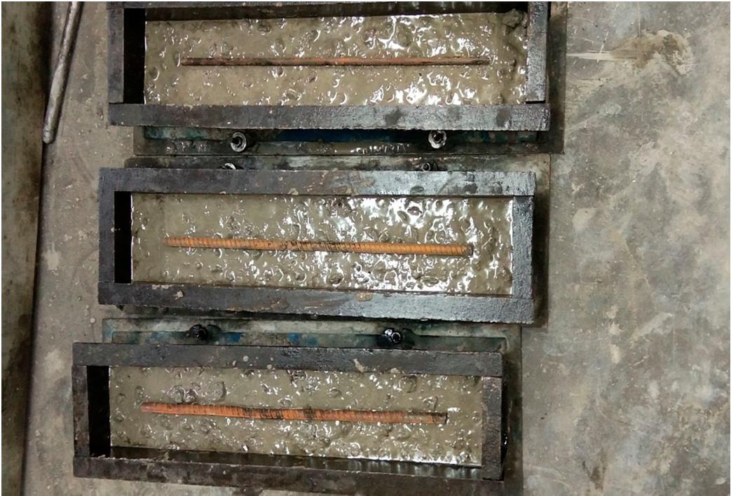
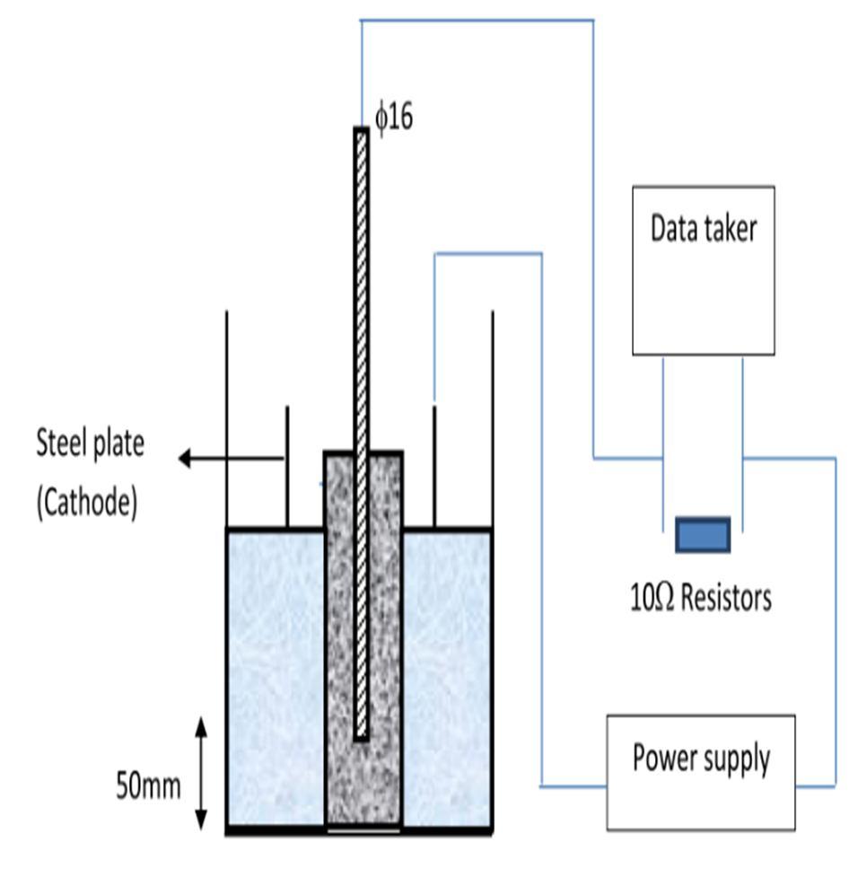
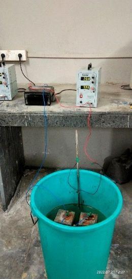
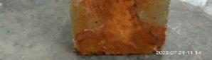
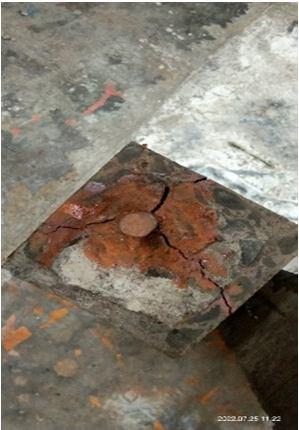
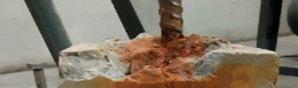
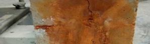
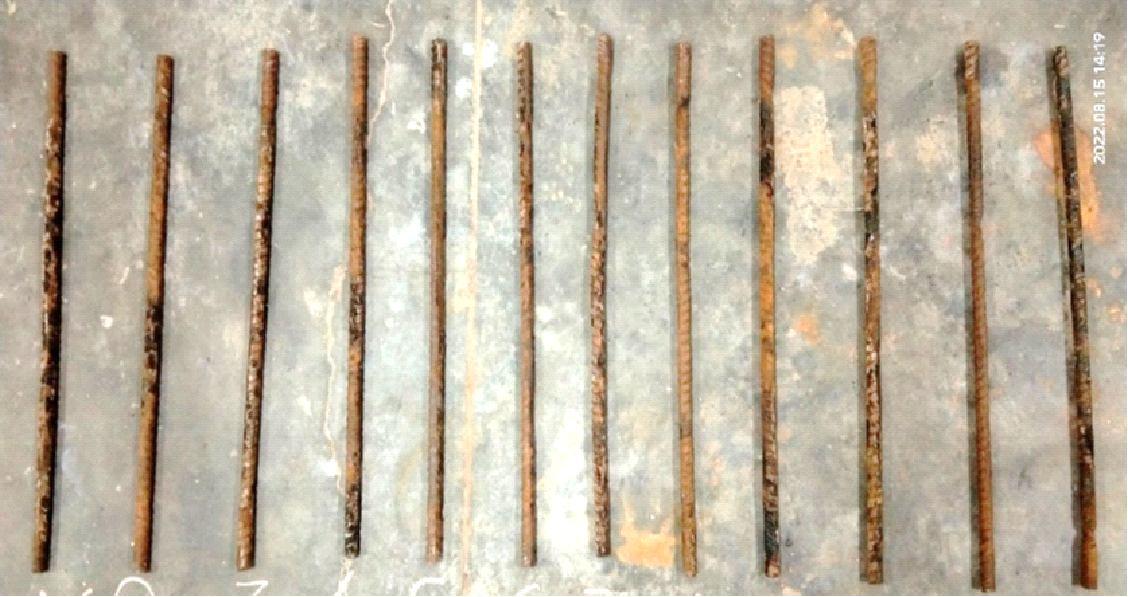
2) Accelerated Corrosion Test: Accelerated corrosion test was employed to simulate the corrosion of steel reinforcement in concrete. The corrosion process was accelerated by impressing an anodic potential between rebar (anode) and steel plate (cathode) to record the variation of current with time. Concrete specimens of 100 x 100 x 500 mm cylinder were used after curing in water for 28 days. Deformed steel bars of 12 mm diameter and 400 mm in length are used and fixed in the center of the specimens after being cleaned and accurately weighed. The steel bar has an effective cover of 50 mm at the bottom as well as at all other sides. The reinforced concrete specimens were immersed in a 3.5% sodium chloride solution in a ‘‘3 days wet’’ and ‘‘4 days dry’’ cyclic regime to accelerate the corrosion. Readings for each type of mixes were taken and recorded every hour using an automatic data taker (Ammeter). The schematic of the accelerated corrosion test setup is presented in Fig. given below. The steel bar (anode) of the sample is connected to a 10 V DC power supply. The negative terminal of the DC power source is connected to the stainless steel plate (cathode). The impressed current flow is measured regularly and test is stopped when the initiation of corrosion is detected. A rapid increase in current flow indicates the formation of cracks in concrete samples. In order to measure the weight loss measurement, the corroded steel is retrieved from the broken samples and weight to be compared with the initial weight after accelerated corrosion test.
ISSN: 2321 9653; IC Value: 45.98; SJ Impact Factor: 7.538 Volume 10 Issue X Oct 2022 Available at www.ijraset.com
After applying the current for a given time, the degree of induced corrosion can be theoretically calculated according to Faraday’s law as follows: WIT app Mth F
Mth = theoretical mass of rust per unit surface area of the bar (g/cm2),
W = equivalent weight of steel which is taken as the ratio of atomic weight of iron to the valency of iron (27.925 g),
Figure No. 4.8: Schematic of accelerated corrosion test setup
I app = applied current density (Amp/cm2),
T = duration of induced corrosion (s), F = Faraday’s constant (96,487 Amp s). The actual mass of corroded products per unit surface area is measured according to Eq. given below. by gravimetric method in accordance with ASTM G1 on rebars extracted from the concrete by breaking the specimens after the accelerated corrosion test where, WWif M
M ac = actual mass of rust per unit surface area of the bar (g/cm2),
Wi = initial weight of the bar before corrosion (g),
W f = weight after corrosion (g) for a given duration of induced corrosion (T),
D = diameter of the rebar (cm),
L = length of the rebar sample (cm).
The weight of rusting in percentage can be calculated as follows:
ISSN: 2321 9653; IC Value: 45.98; SJ Impact Factor: 7.538 Volume 10 Issue X Oct 2022 Available at www.ijraset.com
0.00080
0.00070
0.00060
0.00050
0.00040
0.00030
M1 M2 M3 M4
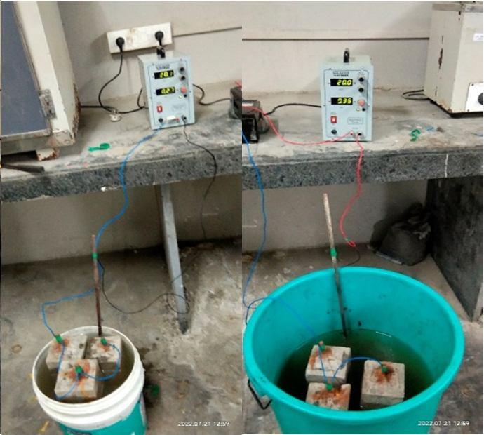
Figure No. 4.9: Average mass of rust per unit surface area of 40% Fly Ash volume for different proportion of UFFA
The Accelerated corrosion test results are shown in Figure 4.9. The above chart illustrates the actual mass of rust per unit surface area of the bar relationships with different combinations of high volume fly ash concrete. The results show that the concrete containing 6% ultra fine fly ash is resulting in 0.00046 gm/sqcm actual mass of rust which is minimum as compare to others. The similar results are seen for the 12% of ultra fine fly ash which is resulting in 0.00045 gm/sqcm actual mass of rust which is minimum. As the actual mass of rusting is minimum it means that the particular percentages of ultra fine fly ash show the better resisting capacity to the corrosion of reinforcement rebars. The above results are shown for the 40% replacement of fly ash with different percentages of UFFA. The remaining two combinations i.e.M2 and M3 shows the higher results as compared to others. It means that this combination has lesser resisting capacity to the rusting or corrosion of rebar reinforcement. The main reason of the higher rusting of rebar are the cracks. Once the cracks appeared, it accelerates the corrosion that is evident in the higher rusting.
Mac (gm/sqcm)
0.00080
0.00070
0.00060
0.00050
0.00040
Mac (gm/sqcm) 0.00030
M5 M6 M7 M8
Figure No. 4.10: Average mass of rust per unit surface area of 50% Fly Ash volume for different proportion of UFFA
ISSN: 2321 9653; IC Value: 45.98; SJ Impact Factor: 7.538 Volume 10 Issue X Oct 2022 Available at www.ijraset.com
The Figure 4.10 illustrates the actual mass of rust per unit surface area of the bar relationships with different combinations of high volume fly ash concrete. The above results are shown for the 50% replacement of fly ash with different percentages of UFFA. As per the results the concrete containing 6% ultra fine fly ash is resulting in 0.00044 gm/sqcm actual mass of rust which is minimum out of all other combinations of concrete. So, it is the evident that 6% replacement of ultra fine fly ash along with 50% fly ash gives the better resistance to corrosion of reinforcement bars. As longer the time of concrete to crack better the corrosion resistance. The above results are taken after conducting the acceleration corrosion test on casted reinforced concrete beams. The other combinations show the higher mass of rusting because the cracks on beams are seen in shorter time due to this oxygen and chloride ions penetrated rapidly through the specimens and accelerated the corrosion that is results in high rusting of rebars. The measurement of mass loss is known as the most reliable method to investigate the degree of corrosion.
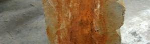
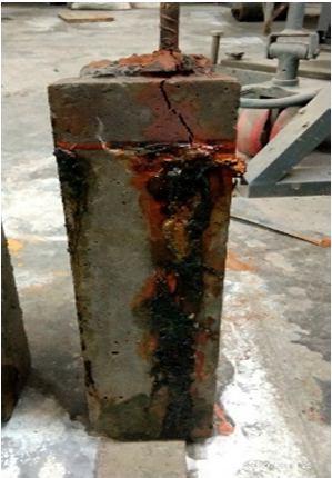
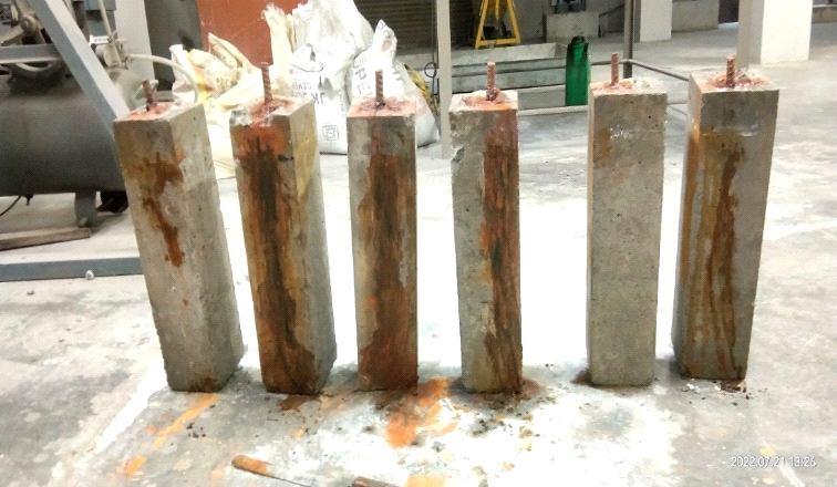
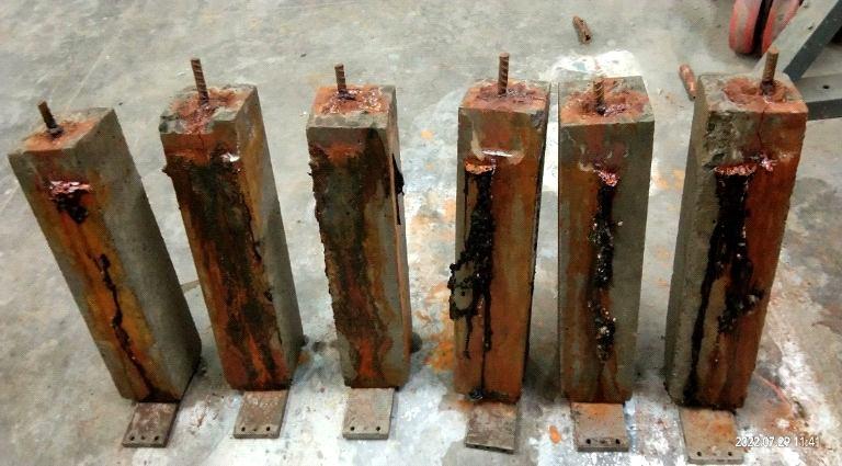
Photograph No. 4.4: Test specimen after accelerated corrosion test
0.00080
0.00070
Mac (gm/sqcm)
0.00060
0.00050
0.00040
0.00030
M9 M10 M11 M12
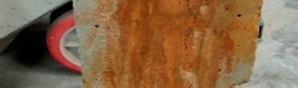
Figure No. 4.11: Average mass of rust per unit surface area of 60% Fly
for different proportion of UFFA
The above Figure 4.11 shows the relationship between actual mass of rust per unit surface area of the bar with different combinations of high volume fly ash concrete. The results show that M9 combination (i.e. 6% of ultra fine fly ash) have the minimum mass of rusting as compared with other combinations of concrete with different percentages of ultra fine fly ash. The concrete containing 6% of ultra fine fly ash with 60% of fly ash have the mass of rust equal to 0.00056 gm/sqcm. The Accelerated corrosion test is conducted until the cracks are appeared on the surface of concrete specimens and at the end of test we can get the result of corrosion of rebars from which we can calculate mass of rusting. In the process of rusting the natural compound is dissolved and oxidized to form iron hydroxide Fe(OH)3 , which further forms nFe2O3.mH2O (red rust) to generate a rust layer on the surface of the steel. Also, it can be seen from the results that the concrete combination M12 (i.e.12% of ultra fine fly ash) shows the similar results as the result of high volume fly ash concrete containing 6% ultra fine fly ash. The Fig. shows the results for the 60% of fly ash with different percentages of ultra fine fly ash taken for experimental purpose.
ISSN: 2321 9653; IC Value: 45.98; SJ Impact Factor: 7.538
Volume 10 Issue X Oct 2022 Available at www.ijraset.com
30.00
25.00
20.00
15.00
10.00
M1 M2 M3 M4
The Figure 4.12 illustrates the weight of rusting of the bar relationships with different combinations of high volume fly ash concrete. The current variation with time was recorded by ammeter until the corrosion cracks appear on the surface of concrete specimens. In this study, the ultra fine fly ash took more than 600 h to crack. Once the crack appeared, oxygen and chloride ions penetrated rapidly through the specimens and accelerate the corrosion that was determined with the high current readings. In above case the concrete containing 6% ultra fine fly ash shows the minimum weight of rusting. It describes that for the 6% ultra fine fly ash combination with 40% of fly ash takes longer time to crack due to higher resistance of the concrete to chloride penetration and reduced porosity. The similar results can be seen for the 12% of ultra fine fly ash along with 40% of fly ash (i.e. M4). This composition also shows the minimum weight of rusting as compared to others. The Fig. Shows the weight of rusting data for 40% replacement of fly ash with various combinations of ultra fine fly ash. The results for M2 and M3 shows higher results means it has lower resistance capacity to the corrosion of reinforcement. It happens due to the weak bond between steel and concrete which accelerates the cracks and ultimately it results in higher corrosion.
35.00
The weight of Rusting (%)
30.00
25.00
20.00
15.00
The weight of Rusting (%) 10.00
M5 M6 M7 M8
The Figure 4.13 shows the weight of rusting data for 50% replacement of fly ash with various combinations of ultra fine fly ash. The Fig. illustrates the weight of rusting of the bar relationships with different combinations of high volume fly ash concrete. As per the results the concrete containing 6% ultra fine fly ash shows the minimum weight of rusting out of the all other combinations of high volume fly ash concrete. It is the evident that M5 composition (i.e.6% UFFA) have the higher resistance to the corrosion as compared to other concretes. From the given results it can be seen that 6% ultra fine fly ash shows the 21.13% weight of rusting which is minimum. In the process of rusting the natural compound is dissolved and oxidized to form iron hydroxide Fe(OH)3 , which further forms nFe2O3.mH2O (red rust) to generate a rust layer on the surface of the steel. Under accelerated corrosion, the oxygen near the steel bar is insufficient, and the oxidation of iron hydroxide Fe(OH)3 is partially changed to Fe3O4 (black rust).The M6 and M8 concretes shows the higher weight of rusting because it gets cracked in shorter time and as the crack width goes on increasing the corrosion rate increases resulting higher weight of rusting.
ISSN: 2321 9653; IC Value: 45.98; SJ Impact Factor: 7.538 Volume 10 Issue X Oct 2022 Available at www.ijraset.com
35.00
30.00
25.00
20.00
15.00
10.00
M9 M10 M11 M12
Figure No. 4.14: Average weight of rust of 60% Fly Ash volume for different proportion of UFFA
The Figure 4.14 shows the rusting weight results for the 60% of fly ash with different ultra fine fly ash. This Fig. Illustrate the relationship between the weight of rusting of the bar with different combinations of high volume fly ash concrete. The result shows that the weight of rusting of 6% ultra fine fly ash can be seen minimum when compared with other types of concrete shown in Figure 4.14. Similarly, the concrete type containing 12% of ultra fine fly ash gives the minimum percentage of weight of rusting. Due to longer time takes to get crack on specimen surface it has better corrosion resistance. The weight of rusting is higher for M10 and M11 i.e. 8 and 10% of ultra fine fly ash along with 60% of fly ash respectively. The reason behind it was in accelerated corrosion test, alternative drying and wetting process was done. Due to this artificially created severe environment it accelerates the rusting of reinforcement and it start losing bond with the concrete and then the gases formed between the gaps which is tries to find the way out resulting in cracks on specimen surface. When time taken for this whole process is lesser it gives the higher percentage of rusting of reinforcement.
The weight of Rusting (%)
35.00
30.00
25.00
20.00
15.00
The weight of Rusting (%) 10.00
M1 M2 M3 M4 M5 M6 M7 M8 M9 M10 M11 M12
Figure No. 4.15: Average weight of rust of for different proportion Fly Ash volume and UFFA
ISSN: 2321 9653; IC Value: 45.98; SJ Impact Factor: 7.538 Volume 10 Issue X Oct 2022 Available at www.ijraset.com
The Figure 4.16 illustrates the weight of rusting of the bar relationships with different combinations of high volume fly ash concrete under consideration. The current variation with time was recorded by data recorder (ammeter) until the corrosion cracks appear on the surface of concrete specimens. The figure shows that the concrete containing 6% of ultra fine fly ash perform better in terms of lower measured percentages of weight of rusting. In this study, the UFFA6 concrete took more than 600 h to crack. Based on the results obtained, the weight of rusting of 40% fly ash concrete was lower than that of 50% and 60% of fly ash concrete. It indicates that the presence of 6% of UFFA reduced the corrosion of rebar in HVFA concretes. The longer time of HVFA concretes containing UFFA to crack is probably due to the higher resistance of the concretes to chloride penetration. The Fig. shown below shows the actual corrosion of steel in different types of concretes after the accelerated corrosion test. Distinguishable difference can be seen in the appearance on the surface of the different types of concrete after splitting. Also, from the above Figure 4.14, the rusting results of 60% fly ash are nearly similar to that of 40% of fly ash.
The compressive strength of the concrete that was produced at an early age was greatest when it contained 6% UFFA. The addition of 6% UFFA to HVFA concretes results in an increase in the early age compressive strength of the concrete. At seven days, the HVFA concrete that contains forty percent fly ash and six percent UFFA shows the most substantial improvement. The addition of 8% UFFA results in the best compressive strength (after 28 days) of HVFA concrete that contains 50% fly ash. The compressive strength of the concrete that contains 8 weight percent UFFA is the weakest when it is first aged. The addition of 8% UFFA to HVFA concretes results in a reduction in the early age compressive strength of the concrete. At seven days, the HVFA concrete that contains sixty percent fly ash and eight percent UFFA shows the most substantial degradation. The addition of 6% UFFA results in an HVFA concrete mixture with a fly ash content of 50% having the lowest compressive strength after 28 days. Comparing the early age compressive strength of the concrete containing 40% fly ash to the later age compressive strength of the concrete containing 6%, 8%, 10%, and 12% UFFA correspondingly indicates minor difference at early age compressive strength. Out of all of the different combinations of HVFA concrete that have been considered, the one that has the highest corrosion resistance is the concrete that has 6% UFFA and 50% fly ash. Out of all of the different combinations of HVFA concrete that were taken into consideration, the one that contained 8% UFFA and 50% fly ash had the lowest level of corrosion resistance. When compared to the other percentages of UFFA, the corrosion resistance of the concrete that contains 12% UFFA and also has cement replaced by 40% and 60% fly ash in HVFA concrete is the highest. This is because HVFA concrete also contains 60% fly ash. When compared to the other percentages of UFFA, the corrosion resistance of the concrete that contains 8% UFFA and also has cement replaced by 40% and 50% fly ash in HVFA concrete is lower. This is because HVFA concrete also contains 40% and 50% fly ash. The high volume fly ash concrete (HVFA) with combinations of 50% fly ash and 12% UFFA and 60% fly ash with 6%, 10%, and 12% UFFA exhibits a quick rate of rebar corrosion with improved corrosion resistance.
[1] Paratibha Aggarwal, Yogesh Aggarwal “Carbonation and corrosion of SCC”, National Institute of Technology Kurukshetra, Kurukshetra, India 147 193.
[2] Seyoon Yoon, Paulo J.M. Monteiro, Donald E. Macphee , Fredrik P. Glasser, Mohammed Salah Eldin Imbabi “Statistical evaluation of the mechanical properties of high volume class F fly ash concretes”, School of Engineering, University of Aberdeen, Fraser Noble Building, King’s College, Aberdeen AB24 3UE, UK, Department of Civil and Environmental Engineering, University of California, Berkeley, A 94720, USA cDepartment of Chemistry, University of Aberdeen, Meston Building, King’s College, Aberdeen AB24 3UE, UK (23 January 2014) 432 442.
ISSN: 2321 9653; IC Value: 45.98; SJ Impact Factor: 7.538 Volume 10 Issue X Oct 2022 Available at www.ijraset.com
[3] Lingzhu Zhou, Yu Zheng , Yong Yu , Gangbing Song , Linsheng Huo , Yongchang Guo “Experimental study of mechanical and fresh properties of HVFA SCC with and without PP fiber” ,School of Environment and Civil Engineering, Dongguan University of Technology, Dongguan 523808 China, Key Laboratory of Coastal and Offshore Engineering, Dalian University of Technology, Dalian 116024, China, Department of Mechanical Engineering, University of Houston, Houston, TX, USA ,Department of Civil and Transportation Engineering Institute, Guangdong University of Technology, Gangzhou 510006 China (15 September 2020).
[4] Faiz U.A. Shaikh , Steve W.M. Supit “Compressive strength and durability properties of high volume fly ash (HVFA) concretes containing ultrafine fly ash (UFFA)”, Department of Civil Engineering, Curtin University, Perth, Australia ( 24 February 2015)192 205.
[5] Faiz Uddin Ahmed Shaikh, Steve W.M. Supit “Chloride induced corrosion durability of high volume fly ash concretes containing nano particles”, Department of Civil Engineering, Curtin University, Perth, Australia (19 September 2015)208 225.
[6] Fengyin Du , Zuquan Jin , Wei She , Chuansheng Xiong , Guangyan Feng , Junfeng Fan “Chloride ions migration and induced reinforcement corrosion in concrete with cracks: A comparative study of current acceleration and natural marine exposure”, Southeast University, Nanjing 211189, PR China ,College of Civil Engineering, Qingdao University of Technology, Qingdao, PR China ,Cooperative Innovation Center of Engineering Construction and Safety in Shandong Blue Economic Zone, Qingdao 266033, PR China ,SOBUTE New Materials Co., Ltd., Nanjing 211103, PR China , Hunan University, Changsha 410082, PR China ,Qingdao Sansheng Investment Co., Ltd., Qingdao 266121, PR China (27 June 2020) 1 11.
[7] F.U.A. Shaikh , S.W.M. Supit, P.K. Sarker “A study on the effect of nano silica on compressive strength of high volume fly ash mortars and concretes”, Department of Civil Engineering, Curtin University, Perth, Australia (19 April 2014)433 442.
[8] Hailong Ye , Chuanqing Fu , Nanguo Jin , Xianyu Jin “Performance of reinforced concrete beams corroded under sustained service loads: A comparative study of two accelerated corrosion techniques”, College of Civil Engineering and Architecture, Zhejiang University, Hangzhou 310027, PR China ,Department of Civil and Structural Engineering, The University of Sheffield, Sheffield S1 3JD, United Kingdom,College of Civil Engineering and Architecture, Zhejiang University of Technology, Hangzhou 310034, PR China ( 15 December 2017)286 297.
[9] Du Fengyin, Jin Zuquan ,Zhao Tiejun, Dai Xueyan “Electrochemical Chloride Extraction From Corrosion Resistant Steel Bar Reinforced Concrete”, College of Civil Engineering, Qingdao University of Technology, Qingdao, China ( 5 June 2018)7076 7094.
[10] Alexander Michel, Brad J. Pease , Mette R. Geiker , Henrik Stang , John Forbes Olesen “Monitoring reinforcement corrosion and corrosion induced cracking using non destructive x ray attenuation measurements”, Technical University of Denmark (DTU), Department of Civil Engineering, Brovej Building 118, DK 2800 Kgs. Lyngby, Denmark , Norwegian University of Science and Technology (NTNU), Department of Structural Engineering, Trondheim, Norway ( 17 June 2011)1085 1094.
[11] M. Babaee, A. Castel “Chloride induced corrosion of reinforcement in low calcium fly ash based geopolymer concrete”, Centre for Infrastructure Engineering and Safety, School of Civil and Environment Engineering, University of New South Wales Sydney, NSW, 2052, Australia (18 May 2016)96 107.
[12] T. Cheewaket, C. Jaturapitakkul , W. Chalee “Initial corrosion presented by chloride threshold penetration of concrete up to 10 year results under marine site”, Department of Civil Engineering, Faculty of Engineering, King Mongkut’s University of Technology Thonburi, Bangkok 10140, Thailand Department of Civil Engineering, Faculty of Engineering, Burapha University, Chonburi 20131, Thailand ( 13 September 2012) 693 698.
[13] enjun Zhu , Raoul François , Yong Liu “Propagation of corrosion and corrosion patterns of bars embedded in RC beams stored in chloride environment for various periods”, Tunnel and Underground Engineering Research Center of Ministry of Education, School of Civil Engineering, Beijing Jiaotong University, Beijing 100044, China LMDC, Université de Toulouse, INSA, UPS, Toulouse, France ,Department of Civil & Environmental Engineering, National University of Singapore, 1 Engineering Drive 2, Singapore 117576, Singapore ( 27 March 2017)147 156.
[14] Hailong Ye , Chuanqing Fu , Nanguo Jin , Xianyu Jin “Performance of reinforced concrete beams corroded under sustained service loads: A comparative study of two accelerated corrosion techniques”, College of Civil Engineering and Architecture, Zhejiang University, Hangzhou 310027, PR China , Department of Civil and Structural Engineering, The University of Sheffield, Sheffield S1 3JD, United Kingdom,College of Civil Engineering and Architecture, Zhejiang University of Technology, Hangzhou 310034, PR China (25 October 2017) 286 297.
[15] Chong Cao, Moe M.S. Cheung, Ben Y.B. Chan “Modelling of interaction between corrosion induced concrete cover crack and steel corrosion rate”, Department of Civil and Environmental Engineering, The Hong Kong University of Science and Technology, Clear Water Bay, Hong Kong, China, Western China Earthquake and Hazards Mitigation Research Center, Sichuan University, Chengdu, Sichuan 610065, China (29 November 2012) 97 109.
[16] Yuxi Zhao, Jianfeng Dong, Yingyao Wu , Hailong Wang , Xiangyang Li , Qingfeng Xu “Steel corrosion and corrosion induced cracking in recycled aggregate concrete”, Institute of Structural Engineering, Zhejiang University, Hangzhou 310058, China ,Shanghai Key Laboratory of New Technology Research on Engineering Structure, Shanghai 200032, China (18 April 2014).
[17] Fengyin Du, Zuquan Jin , Chuansheng Xiong , Yong Yu and Junfeng Fan “Effects of Transverse Crack on Chloride Ions Diffusion and Steel Bars Corrosion Behavior in Concrete under Electric Acceleration” College of Civil Engineering, Qingdao University of Technology, Qingdao 266033, China, Cooperative Innovation Center of Engineering Consrtuction and Safety in Shandong Blue Economic Zone, Qingdao 266033, China,Key Laboratory of Coast Civil Structure Safety, Tianjin University, Ministry of Education, Tianjin 300350, China (5 August 2019)1 20.
[18] Rahul Patel “Prevention of Corrosion of Steel Reinforcement in Concrete” Assistant Professor, Department of Civil Engineering, University Institute of Technology, RGPV, Bhopal 462 033, India. ( 25 September 2019) 1 7.
[19] M. B. Otieno, M. G. Alexander and H. D. Beushausen “Corrosion in cracked and uncracked concrete influence of crack width, concrete quality and crack reopening” University of Cape Town, 393 404.