
ISSN: 2321 9653; IC Value: 45.98; SJ Impact Factor: 7.538 Volume 10 Issue XI Nov 2022 Available at www.ijraset.com


ISSN: 2321 9653; IC Value: 45.98; SJ Impact Factor: 7.538 Volume 10 Issue XI Nov 2022 Available at www.ijraset.com

Abstract: Advances in construction technology, materials, structural systems and analytical methods for analysis and design facilitated the growth of high rise buildings. Structural design of high risebuildings is governed by lateral loads due to wind or earthquake. Lateral load resistance of structure is provided by interior structural system or exterior structural system. Usually shear wall core, braced frame and their combination with frames are interior system, where lateral load is resisted by centrally located elements. While framed tube, braced tube structural system resists lateral loads by elements provided on periphery of structure. It is very importantthat the selected structural system is such that the structural elements are utilized effectively while satisfying design requirements. Recently Inclined columns structural system is adopted in tall buildings due to its structural efficiency and flexibility in architectural planning. Compared to closely spaced vertical columns in framed tube. Inclined column should be placed at the exterior surface of the building. Due to inclined columns lateral loads are resisted by axial action of the diagonal compared to bending of vertical columns in framed structure. Inclined column structures generally do not require core because lateral shear canbe carried by the diagonals on the periphery of building. Analysis and design of G+9 storey building is presented. A regular floor plan of 36 m × 36 m size is considered. Staad pro software is used for modelling and analysis of structural members. All structural members aredesigned as per IS 456:2000 considering all load combinations. Dynamic along wind and across wind are considered for analysis and design of the structure. Load distribution in system is also studied for G+9 storey building. Similarly, analysis and design of G+9 storey vertical column structures is carried out with and without weak storey. Comparison ofanalysis results in terms of time period, top storey displacement and inter storey drift will be presented in this study with or without inclined column in frame structure.
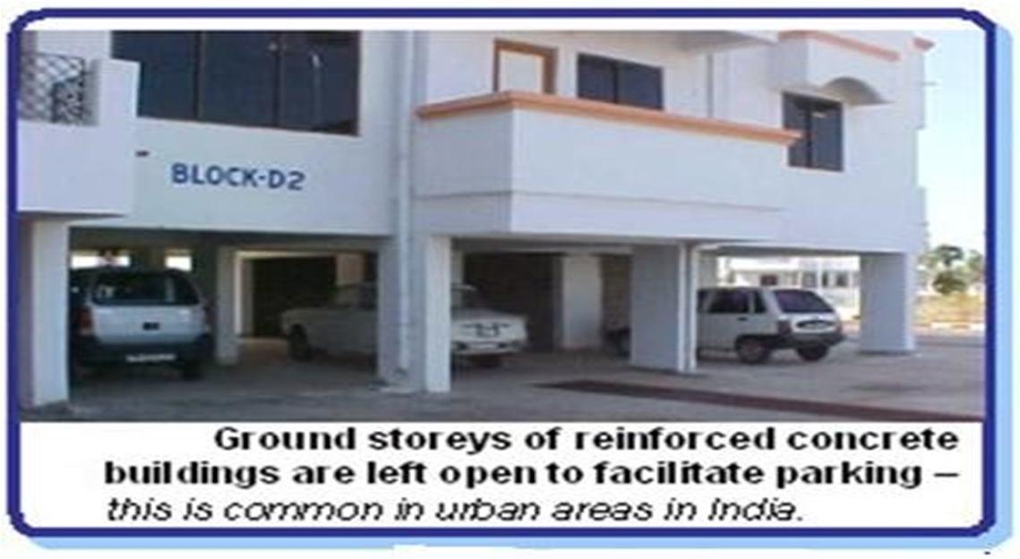
Soft storey is a common building weakness. The term soft storey explains one level of a buildingthat is appreciably more flexible than the stories above it and the floors or the foundation under it. A soft storey can be defined on the basis of the stiffness of the adjacent floor stiffness, building can be said to be soft storey or week storey if the stiffness of that particular level is less than 70 % with respect to floor instantly above it or less than 80 % of average stiffness oft the three floors above it. Some building in which height of floor is greater in ground these type of building is knowing as Open Ground storey buildings or soft storey. The weak or soft storey commonly exists at the ground storey level, but it might be at any other storey level. Soft storeybuildings have a lot of open space for example, parking garage, restaurants or floors with lotsof windows. The behavior of soft storey building in an earthquake is very crucial because the soft storey building is more flexible in seismic condition, vibration is happening in the soft storey building so we provide shear wall in a soft storeybuilding (shear wall resists the effect of an earthquake).

Fig. 1. 1 Soft Storey Building

ISSN: 2321 9653; IC Value: 45.98; SJ Impact Factor: 7.538 Volume 10 Issue XI Nov 2022 Available at www.ijraset.com


Reinforced concrete frame structures have become a common form of construction with masonryinfill in urban and semi urban areas in the world. The infill framed structures are made and analyzed by the combination of a moment resisting plane frame and infill masonry walls. The infill masonry may be of brick, concrete blocks, or stones. Ideally in present time the reinforced concrete frame is filled with bricks as non structural wall for partition of the rooms because of itsadvantages such as, thermal insulation, durability, cost and simple construction technique. Nowadays, many buildings are constructed having a unique feature i.e. the ground floor remains open, which means the columns in the ground floor do not have any partition walls between them. This type of structure (Fig. 1.2) having no infill masonry walls in ground floor, but having infill masonry walls in all the upper floors, are called Open Ground Storey (OGS) Buildings. This open ground floor structure is also termed as a structure with ‘soft storey at Ground Floor’. OGS buildings are also known as open first storey building (when the floor numbering starts with one from the ground floor itself), pilots, or stilted buildings. Open first storey is nowadays unavoidable feature for the most of the urban multi storey buildings because social and functional needs for parking, restaurant, commercial use etc. are compelling to provide an open first Storeyin high rise structure. Parking has become a necessary feature for the most of urban multistoried buildings as the population is increasing at a very fast rate in urban areas leading to crisis of vehicle parking space. Hence the trend has been to use the ground floor of the building itself for parking purpose.
There is major advantage of this type of buildings functioning, but from the seismic performancepoint of view, such structures are considered to have increased vulnerability. Though multi storied buildings with parking floor (soft storey) are vulnerable to collapse due to seismic forces,their construction is still popular. The Soft Storey buildings are usually designed as framed structures without regard to structural action of wall (masonry infill walls). In India current structural design methods, infill walls are considered as non structural element and their strengthand stiffness are ignored during analysis and design. The effect of infill panels on RC framed structures if subjected to earthquake is widely accepted and has been subjected to numerous experimental and analytical investigations over last 5 decades.
ISSN: 2321 9653; IC Value: 45.98; SJ Impact Factor: 7.538 Volume 10 Issue XI Nov 2022 Available at www.ijraset.com

Since the presence of a soft storey which has less rigidity than other stories and if this point was not taken into consideration, it causes the construction to be affected by the earthquake because columns in this portion are forced by the earthquake more than the ones in the other parts of the building. Studies conducted suggest that walls raise the rigidity at a certain degree in theconstruction of buildings.
Behaviour of construction is divided into two parts, from the point where there is no soft storey, the building with equal rigidity between the stories; the displacement of the peak points at the moment of an earthquake causes the other building with a soft storey to get damaged because theconstruction with a soft storey cannot show the same rigidity. For example, the top point of a ten storey building with no soft storey performs 10 unit displacement, another building with the same specification but having a soft storey at the entry floor and with no necessary precautioncan show the same displacement 10 unit at this floor level. According to this outcome, a soft storeyin the upper stories of the building is not so effective.


Where; “u” is the displacement

ISSN: 2321 9653; IC Value: 45.98; SJ Impact Factor: 7.538 Volume 10 Issue XI Nov 2022 Available at www.ijraset.com


The
1) Step 1 Selection of building geometry and Seismic zone: The behavior of all the models is studied for Zone II of Seismic zones of India as per IS code 875 PART II 1987 for which zone factor (Z) is 0.10
ISSN: 2321 9653; IC Value: 45.98; SJ Impact Factor: 7.538 Volume 10 Issue XI Nov 2022 Available at www.ijraset.com

2) Step 2 Selecting geometry of 10 stories (G+9) of plan area 36m x 36m
3. 1
SR. NO. Cases performed Case No. Seismic zone Inclined column
1. Building without Soft Storey Without Inclined Column I 1 (zone II, Bhopal ) Without Inclined Column
2. Ground Floor Soft Storey, Without Inclined Column II 1 (zone II, Bhopal ) Without Inclined Column
3. 2nd Floor Soft Storey, Without Inclined Column III 1 (zone II, Bhopal ) Without Inclined Column
4. 4th Floor Soft Storey, Without Inclined Column IV 1 (zone II, Bhopal ) Without Inclined Column
5. 6th Floor Soft Storey, Without Inclined Column V 1 (zone II, Bhopal ) Without Inclined Column
6. 8th Floor Soft Storey, Without Inclined Column VI 1 (zone II, Bhopal ) Without Inclined Column
7. Top Floor Soft Storey, Without Inclined Column VII 1 (zone II, Bhopal ) Without Inclined Column
8. Ground Floor Soft Storey, With Inclined Column inHorizontally Placed floor
9. 2nd Floor Soft Storey, With Inclined Column in Horizontally Placed floor
10. 4th Floor Soft Storey, WithInclined Column in Horizontally Placed floor
11. 6th Floor Soft Storey, WithInclined Column in Horizontally Placed floor
12. 8th Floor Soft Storey, WithInclined Column in Horizontally Placed floor
13. Top Floor Soft Storey, WithInclined Column in Horizontally Placed floor
14. Ground Floor Soft Storey,With Inclined Column at Corners of building
15. 2nd Floor Soft Storey, WithInclined Column at Corners of building
16. 4th Floor Soft Storey, With Inclined Column at Cornersof building
17. 6th Floor Soft Storey, WithInclined Column at Corners
VIII 1 (zone II, Bhopal ) With Inclined Column
IX 1 (zone II, Bhopal ) With Inclined Column
X 1 (zone II, Bhopal ) With Inclined Column
XI 1 (zone II, Bhopal ) With Inclined Column
XII 1 (zone II, Bhopal ) With Inclined Column
XIII 1 (zone II, Bhopal ) With Inclined Column
XIV 1 (zone II, Bhopal ) With Inclined Column

XV 1 (zone II, Bhopal ) With Inclined Column
XVI 1 (zone II, Bhopal ) With Inclined Column
XVII 1 (zone II, Bhopal ) With Inclined Column
of building
18. 8th Floor Soft Storey, WithInclined Column at Corners of building
19. Top Floor Soft Storey, WithInclined Column at Corners of building
20. Ground Floor Soft Storey,With Inclined Column at Centre of building
ISSN: 2321 9653; IC Value: 45.98; SJ Impact Factor: 7.538

Volume 10 Issue XI Nov 2022 Available at www.ijraset.com
XVIII 1 (zone II, Bhopal ) With Inclined Column
XIX 1 (zone II, Bhopal ) With Inclined Column
XX 1 (zone II, Bhopal ) With Inclined Column
21. 2nd Floor Soft Storey, With Inclined Column at Centreof building XXI 1 (zone II, Bhopal ) With Inclined Column
22. 4th Floor Soft Storey, With Inclined Column at Centreof building XXII 1 (zone II, Bhopal ) With Inclined Column
23. 6th Floor Soft Storey, WithInclined Column at Centre of building
24. 8th Floor Soft Storey, WithInclined Column at Centre of building
XXIII 1 (zone II, Bhopal ) With Inclined Column
XXIV 1 (zone II, Bhopal ) With Inclined Column
25. Top Floor Soft Storey, With Inclined Column at Centreof building XXV 1 (zone II, Bhopal ) With Inclined Column
TABLE 3. 2 TOTAL PROBLEM IN
SR. NO. Cases performed Case No. Wind Zone Inclined column
1. Building without Soft Storey Without Inclined Column
2. Ground Floor Soft Storey, Without Inclined Column
3. 2nd Floor Soft Storey,Without Inclined Column
4. 4nd Floor Soft Storey, Without Inclined Column
5. Ground Floor SoftStorey, With Inclined Column
I 1 (Vb= 39m/s, Bhopal ) Without Inclined Column
II 1 (Vb= 39m/s, Bhopal ) Without Inclined Column
III 1 (Vb= 39m/s, Bhopal ) Without Inclined Column
IV 1 (Vb= 39m/s, Bhopal ) Without Inclined Column

V 1 (Vb= 39m/s, Bhopal ) With Inclined Column
6. 2nd Floor Soft Storey, With Inclined Column VI 1 (Vb= 39m/s, Bhopal ) With Inclined Column
7. 4th Floor Soft Storey, With Inclined Column VII 1 (Vb= 39m/s, Bhopal ) With Inclined Column
So, total 7 problems areanalyzed in Staad
ISSN: 2321 9653; IC Value: 45.98; SJ Impact Factor: 7.538 Volume 10 Issue XI Nov 2022 Available at www.ijraset.com

3) Step 3 Modelling of soft stories floor wise.
4) Step 4 Selection of Equivalent inclined column (200 mm x 200 mm) and above I to VII Cases considered.
5) Step 5 Formation of load combination
Types of Primary Loads and Load Combinations: The structural systems are subjected to Primary Load and Load Combinations Cases as per I.S. 875 (Part I, Part II, Part III and Part V). and IS 1893 Part I 2016 framed are given in Table 3.3
TABLE 3. 3 NUMBER OF LOAD

IN EARTHQUAKE AND WIND LOADCALCULATIONS Load case no. Load Case Details 1. E.Q. IN X_DIR. 2. E.Q. IN Z_DIR. 3. DEAD LOAD 4. LIVE LOAD 5. W.L. IN X_DIR. 6. W.L. IN Z_DIR. 7. 1.5 (DL + LL) 8. 1.5 (DL + EQ_X) 9. 1.5 (DL EQ_X) 10. 1.5 (DL + EQ_Z) 11. 1.5 (DL EQ_Z) 12. 1.2 (DL + LL + EQ_X) 13. 1.2 (DL + LL EQ_X) 14. 1.2 (DL + LL + EQ_Z) 15. 1.2 (DL + LL EQ_Z) 16. 1.5 (DL + W.L. _X) 17. 1.5 (DL W.L. _X) 18. 1.5 (DL + W.L. _Z) 19. 1.5 (DL W.L. _Z) 20. 1.2 (DL + LL + W.L._X) 21. 1.2 (DL + LL W.L. _X) 22. 1.2 (DL + LL + W.L. _Z) 23. 1.2 (DL + LL W.L. _Z) 24. 0.9 DL + EQ_X 25. 0.9 DL EQ_X 26. 0.9 DL + EQ_Z 27. 0.9 DL EQ_Z
6) Step 6 Modelling of building frames in STAAD.Pro software
7) Step 7 Analysis of building frames with and without soft stories cases from given seismic zoneand each load combination. 8) Step 8 Comparative study with graph and tables by maximum moments, displacement, storiesdisplacement, drift, axial force and shear force.
Following properties of material have been considered in the modeling Densityof RCC: 25 KN/m3 Density of Masonry: 20 KN/m3 (Assumed)Poisson’s ratio: 0.17 Young's modulus of concrete: 5000√ƒ
ISSN: 2321 9653; IC Value: 45.98; SJ Impact Factor: 7.538 Volume 10 Issue XI Nov 2022 Available at www.ijraset.com

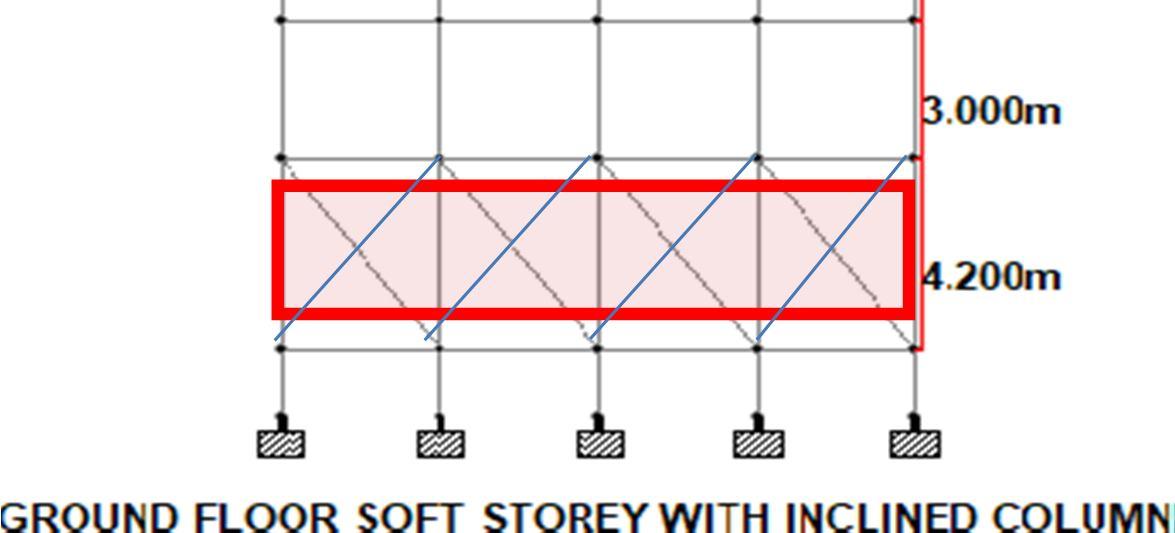
The foundation depth is considered at 1.5 m below ground level and the normal floor height is 3m and soft floor height is considered as 4.2m. 3x3m grid and 12x12m plan is considered with G+5 stories in building is considered.

Following loads are considered for analysis
1) Dead Loads: As per IS: 875 (part 1) 1987Self weight of slab
Slab = 0.15 x 25 = 3.75 KN/m2 (slab thick. 150 mm assumed)Floor Finish load = 1 KN/m2
For External Walls
Masonry Wall Load (floor height 3m) = 0.2 m x 2.5 m x 20 KN/m3 = 10.0 KN/m Masonry Wall Load (floor height 4.2m) = 0.2 m x 3.7 m x 20 KN/m3 = 14.8 KN/mFor Internal Walls
Masonry Wall Load (floor height 3m) = 0.1 m x 2.5 m x 20 KN/m3 = 5.0 KN/m Masonry Wall Load (floor height 4.2m) = 0.1 m x 3.7 m x 20 KN/m3 = 7.4 KN/mFor Parapet Walls
MasonryWall Load (wall height 1m) = 0.1 m x 1.0 m x 20 KN/m3 = 2.0 KN/m
2) Live Loads: As per IS: 875 (part 2) 1987Live Load on typical floors = 3 KN/m2
3) Earth Quake Loads for Case I: All Structures are analyzed for earthquake zone IIThe earthquake calculation is as per IS: 1893 [2002]
a. Earth Quake Zone II (Table 2)
b. Importance Factor: 1 (Table 6)
c. Response Reduction Factor: 5 (Table 7) d. Damping: 5% (Table 3)
e. Soil Type: Medium Soil (Assumed)
f. Period in X direction (PX): 0.09*ℎ
√ seconds Clause 7.6.2
Period in X direction (PX) = 0.09x18/√12 = 0.467 0.09*ℎ
g. Period in Z direction (Pz): √ seconds Clause 7.6.2 [21]
Period in X direction (Pz) = 0.09x18/√12 = 0.467Where, h = height of the building dx = length of building in x direction and dz = length of building in z direction
So, Sa/g = 2.5 (as per code)
AhX = (Z/2 x I/R x Sa/g) = 0.1/2 x 1.5/5 x 2.5 = 0.0375
(Z/2 x I/R x Sa/g)0.1/2 x 1.5/5 x 2.5 = 0.0375
ISSN: 2321 9653; IC Value: 45.98; SJ Impact Factor: 7.538

Volume 10 Issue XI Nov 2022 Available at www.ijraset.com
Where, V = Base shear
W = weight of structure =16758 kNVx = 0.0375 x 16758 = 628.425 kN
Vz = 0.0375 x 16758 = 628.425 kN
4) Earth Quake Loads Case II to VII:
All Structures are analyzed for earthquake zone II The earthquake calculation is as per IS: 1893 [2002]
a. Earth Quake Zone II (Table 2)
b. Importance Factor: 1 (Table 6)
c. Response Reduction Factor: 5 (Table 7)
d. Damping: 5% (Table 3)
e. Soil Type: Medium Soil (Assumed) 0.09*ℎ
f. Period in X direction (PX): √ seconds Clause 7.6.2
Period in X direction (PX) = 0.09x18/√12 = 0.467

g. Period in Zdirection (Pz): 0.09*ℎ
√ seconds Clause 7.6.2 [21]
Period in X direction (Pz) = 0.09x18/√12 = 0.467Where, h = height of the building dx = length of building in x direction and dz = length of building in z direction
So, Sa/g = 2.5 (as per code)
AhX = = (Z/2 x I/R x Sa/g) 0.1/2 x 1.5/5 x 2.5 = 0.0375
AhZ = =
(Z/2 x I/R x Sa/g)0.1/2 x 1.5/5 x 2.5 = 0.0375 V = Ah x W
Where, V = Base shear W = weight of structure
Vx = 0.0375 x 17033 = 638.737 kN Vz = 0.0375 x 33037.83 = 638.737 kN
All the building frames are analyzed for wind zones I (39 m/s). The wind loads areresulting for following wind parameters as per IS: 875(Part 3)
Pz = 0.6 x Vz2
Where, Pz
Design wind pressure in N/m2 at height z Vz
Design wind speed at anyheight z in m/s Vz = Vbxk1xk2xk3

ISSN: 2321 9653; IC Value: 45.98; SJ Impact Factor: 7.538 Volume 10 Issue XI Nov 2022 Available at www.ijraset.com
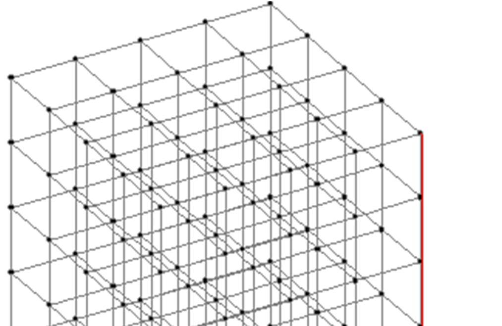
Structural models for different cases are shown in below

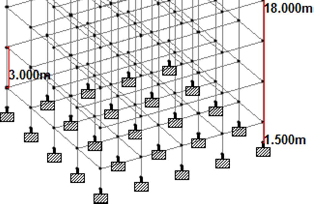

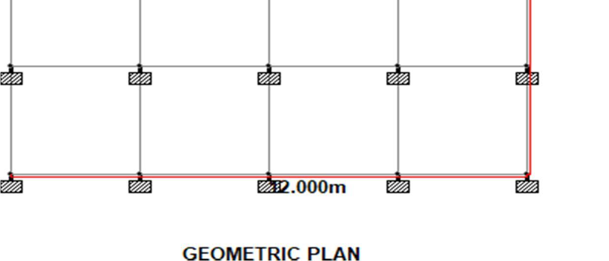
FIG. 4. 1: Structural Geometric Plan
FIG. 4. 2 : Isometric View Of Geometry


ISSN: 2321 9653; IC Value: 45.98; SJ Impact Factor: 7.538 Volume 10 Issue XI Nov 2022 Available at www.ijraset.com

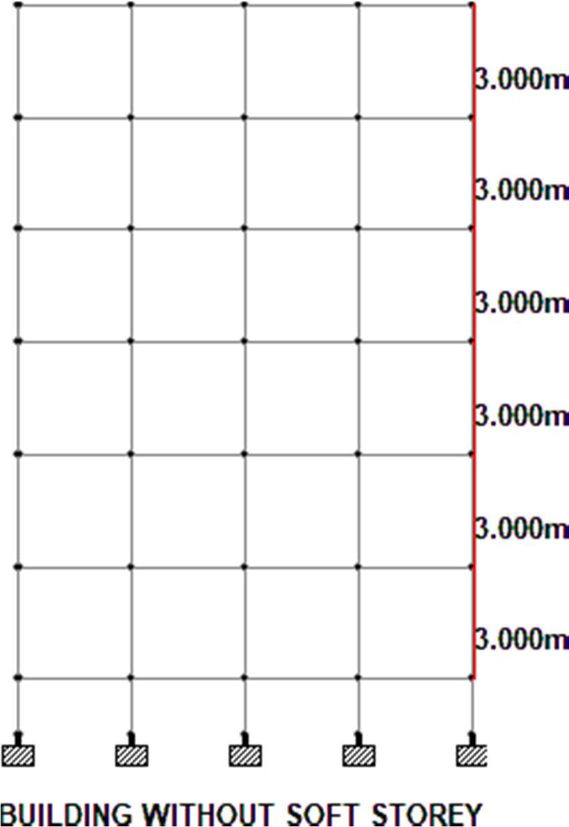

FIG. 4. 3 Building Without Soft Storey (CASE I)
FIG. 4. 4: SOFT STOREY AT GROUND FLOOR (CASE II)
ISSN: 2321 9653; IC Value: 45.98; SJ Impact Factor: 7.538 Volume 10 Issue XI Nov 2022 Available at www.ijraset.com


FIG. 4. 5: Soft Storey AT 2ND Floor (CASE III)
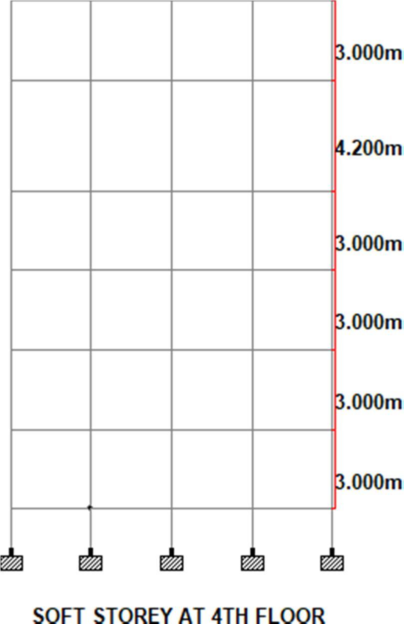

FIG. 4. 6 SOFT STOREY AT 4TH FLOOR (CASE IV)

ISSN: 2321 9653; IC Value: 45.98; SJ Impact Factor: 7.538 Volume 10 Issue XI Nov 2022 Available at www.ijraset.com

FIG. 4. 7 Ground Floor Soft StoreyWith Inclined Column (CASE V)

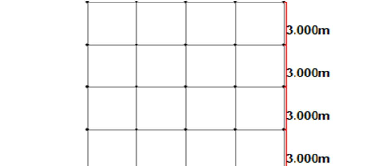

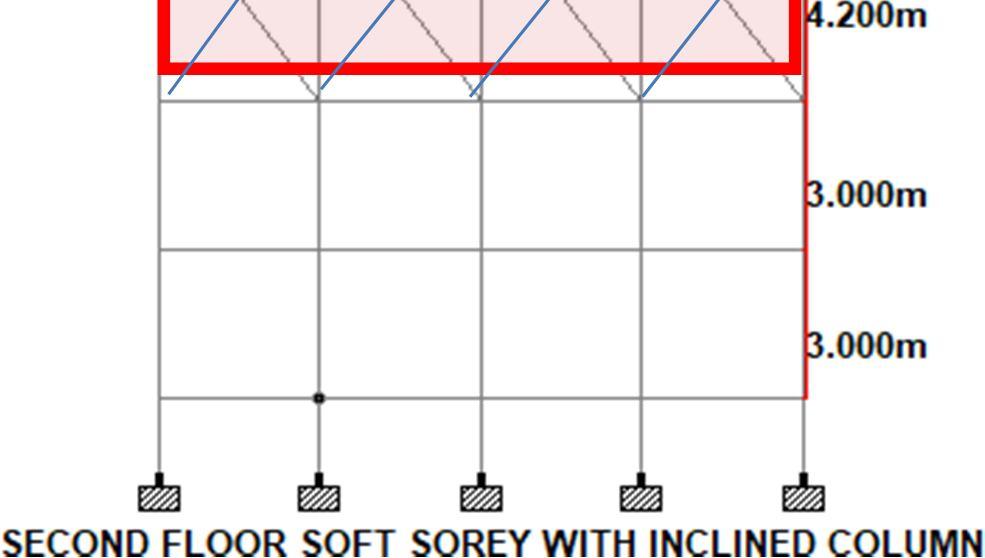
FIG. 4. 8 SECOND FLOOR SOFT STOREY WITH INCLNED COLUMN (CASE VI)
ISSN: 2321 9653; IC Value: 45.98; SJ Impact Factor: 7.538 Volume 10 Issue XI Nov 2022 Available at www.ijraset.com

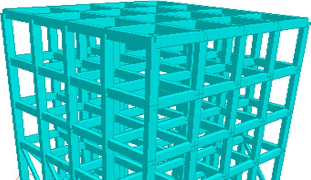
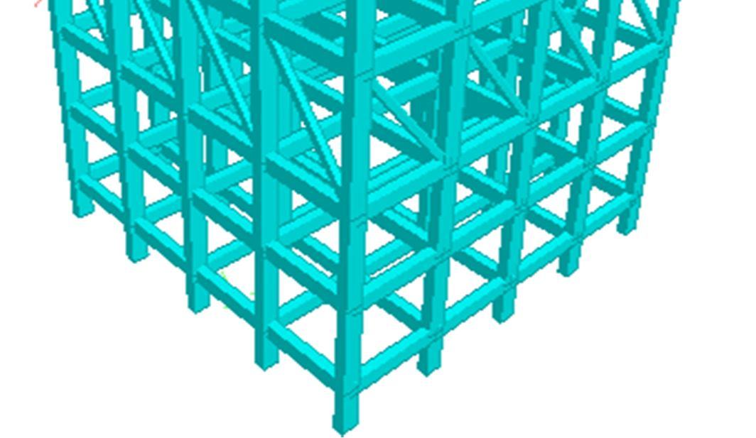
FIG. 4. 9 Fourth Floor Soft StoreyWith Inclned Column (CASE VII) C. Different Positions Of Inclined Column 3 D Models


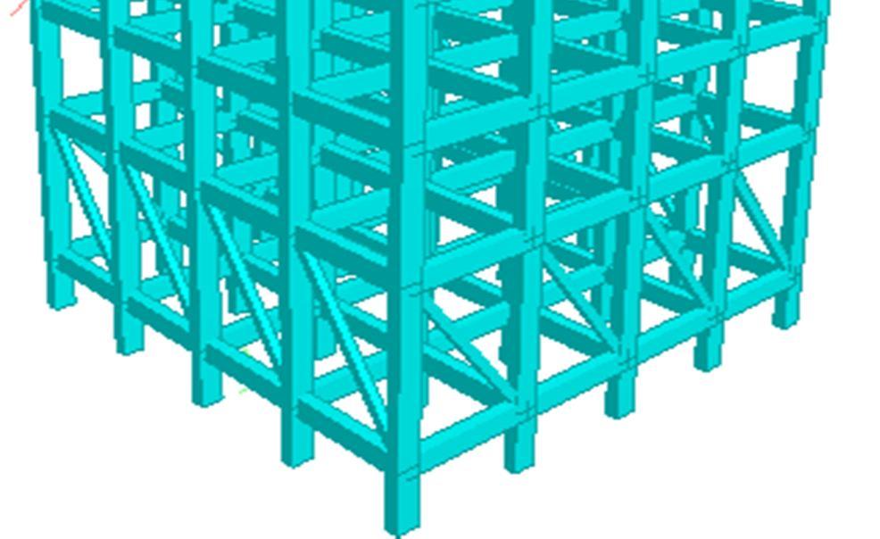
FIG. 4. 10 3D View Of Ground Floor Soft Storey With InclinedColumn Render View
ISSN: 2321 9653; IC Value: 45.98; SJ Impact Factor: 7.538 Volume 10 Issue XI Nov 2022 Available at www.ijraset.com




ISSN: 2321 9653; IC Value: 45.98; SJ Impact Factor: 7.538 Volume 10 Issue XI Nov 2022 Available at www.ijraset.com


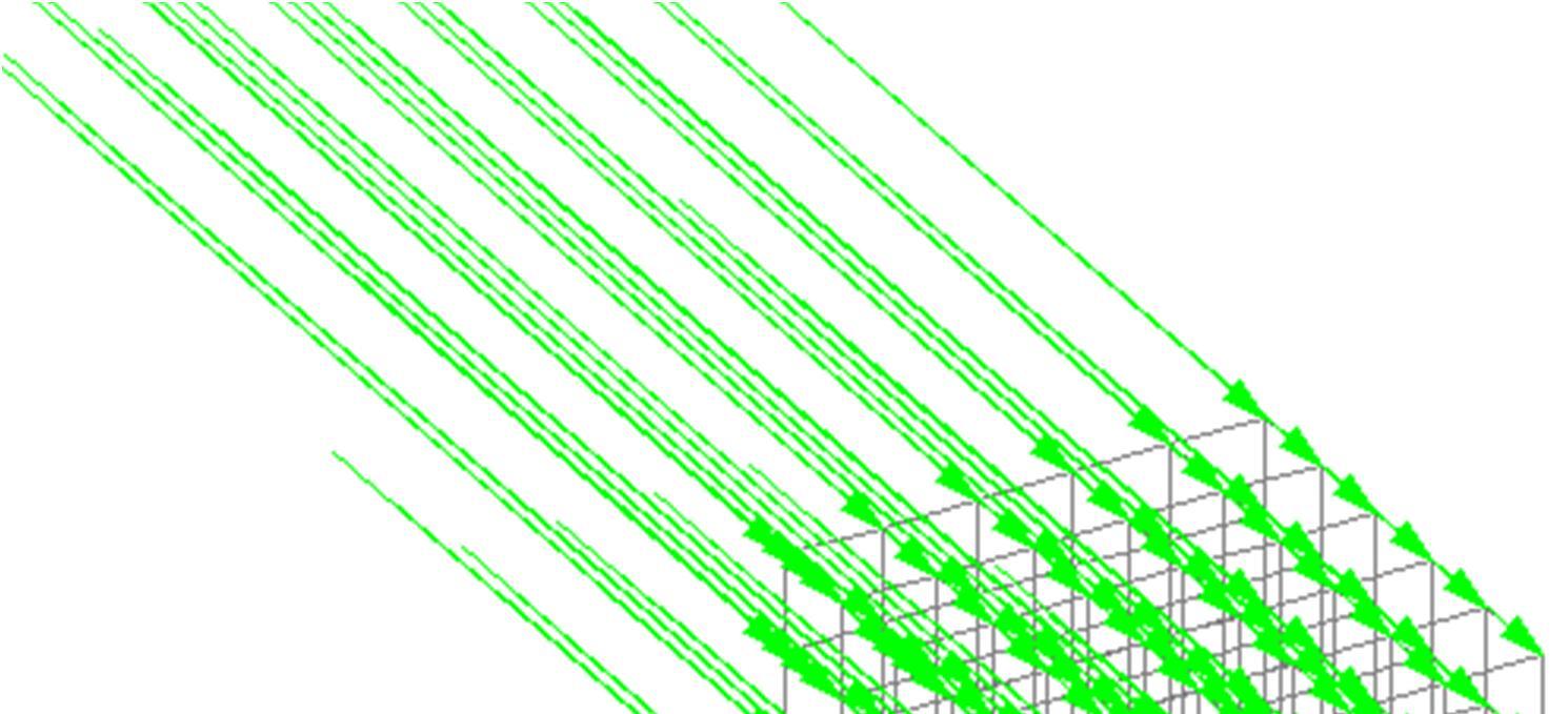

FIG. 4. 11 Seismic Loading In X Direction
FIG. 4. 12 Seismic Loading in Z Direction
ISSN: 2321 9653; IC Value: 45.98; SJ Impact Factor: 7.538 Volume 10 Issue XI Nov 2022 Available at www.ijraset.com

FIG. 4. 13 Dead Load
FIG. 4. 14 Live Load


ISSN: 2321 9653; IC Value: 45.98; SJ Impact Factor: 7.538 Volume 10 Issue XI Nov 2022 Available at www.ijraset.com


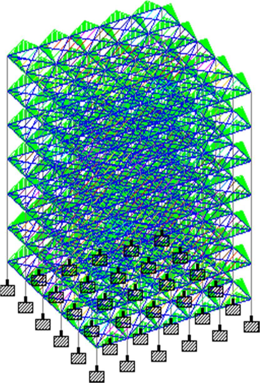
FIG. 4. 17 Wind Loading In X Direction
FIG. 4. 18 Wind Loading In Z Direction
ISSN: 2321 9653; IC Value: 45.98; SJ Impact Factor: 7.538 Volume 10 Issue XI Nov 2022 Available at www.ijraset.com

A. Maximum Displacement
Maximum displacement in X direction for all cases are given in Fig. 5.1and Table 5.1
MAXIMUM DISPLACEMENT (MM) IN X DIRECTION
SOFT STOREY WITHOUT INCLINED COLUMN CORNER INCLINED COLUMN
WITHOUT SOFT STOREY 44.652
Displacment in mm


CENTER INCLINED COLUMN
HORIZONTAL LYPLACED INCLINED COLUMN
GROUND STOREY SOFT 43.614 38.904 38.341 41.562
2nd STOREY SOFT 46.459 41.576 40.888 44.206
4TH STOREY SOFT 46.35 41.692 41.055 44.666
6TH STOREY SOFT 46.783 42.428 41.778 45.845
8TH STOREY SOFT 33.485 30.641 30.26 33.324
TOP STOREY SOFT 32.761 29.999 29.646 32.759
Table 5. 1 Maximum Displacements In X Direction
MAXIMUM DISPLACEMENT (MM) IN X DIRECTION 50 40 30 20 10 0 WITHOUT GROUND 2nd STOREY 4TH STOREY 6TH STOREY 8TH STOREY TOP STOREY SOFT STOREY STOREY SOFT SOFT SOFT Floor Name SOFT SOFT SOFT
MAXIMUM DISPLACEMENT (MM) IN X DIRECTION
MAXIMUM DISPLACEMENT (MM) IN X DIRECTION
MAXIMUM DISPLACEMENT (MM) IN X DIRECTION

MAXIMUM DISPLACEMENT (MM) IN X DIRECTION SOFT STOREY
FIG. 5. 1 Maximum Displacement in X Direction
ISSN: 2321 9653; IC Value: 45.98; SJ Impact Factor: 7.538


Volume 10 Issue XI Nov 2022 Available at www.ijraset.com
1) Maximum Bending Moment
Maximum Bending Moment for all cases are given in Fig. 5.3 and Table 5.3
Maximum Bending Moment in building
Floor Straight BareFrame
Bare Frame With Weak Storey
Bare Frame With WeakStorey and inclined column horizontally

Bare Frame With Weak Storey and inclined column at corners
Bare Frame With Weak Storey and inclined column at centre
0 245.555 232.633 237.043 325.567 310.51 2 245.555 234.047 292.756 324.302 335.104 4 245.555 233.359 292.756 319.482 314.859 6 245.555 239.154 255.477 317.779 313.043 8 245.555 187.334 187.937 238.493 225.236 TOP 245.555 186.72 186.675 238.206 224.723
Table 5. 2 Bending Moment (KN M) IN Beam In X Direction
Moment in kN.m
Maximum Bending Moment in building 400 350 300 250 200 150 100 50 0 0 2 4 6 8 TOP Height of floor in m
Maximum Bending Moment in building
Maximum Bending Moment in building
Maximum Bending Moment in building
Maximum Bending Moment in building
Maximum Bending Moment in building
FIG. 5. 2 Bending Moment (KN M) in Beam
ISSN: 2321 9653; IC Value: 45.98; SJ Impact Factor: 7.538


Volume 10 Issue XI Nov 2022 Available at www.ijraset.com
C. Shear Force
Maximum Shear Force in X direction for all cases are given in Fig. 5.4 and Fig. 5.4
Maximum Shear force in building
Floo r Straight Bare Frame (kN)
Bare Frame With WeakStorey (kN)
Bare Frame With WeakStorey and inclined column horizontally (kN)

Bare Frame With WeakStorey and inclined column at corners (kN)
Bare Frame With WeakStorey and inclined column at centre (kN)
0 177.451 175.039 172.188 175.097 172.257 2 177.451 191.999 188.706 185.139 183.539 4 177.451 191.771 188.706 186.13 184.798 6 177.451 185.956 184.718 181.984 180.144 8 177.451 181.815 182.636 183.506 182.172 TOP 177.451 182.186 182.939 183.995 182.196

Table 5. 4 Shear Force (KN) in Beam in X Direction
Maximum Ahear force in Building
Shear Force in kN
FIG. 5. 4 Shear Force (KN) in Beam in X Direction
ISSN: 2321 9653; IC Value: 45.98; SJ Impact Factor: 7.538


Volume 10 Issue XI Nov 2022 Available at www.ijraset.com
Maximum Shear Force in Z direction for all cases are given in Table 5.6 and Fig. 5.6
Maximum Shear force in building Fz
Floo r Straight Bare Frame (kN)
Bare Frame With WeakStorey (kN)
Bare Frame With WeakStorey and inclined column horizontally (kN)

Bare Frame With WeakStorey and inclined column at corners (kN)
Bare Frame With WeakStorey and inclined column at centre (kN)
0 113.864 103.541 147.136 175.365 169.298 2 113.864 107.559 142.665 170.112 180.281 4 113.864 109.182 142.665 167.604 169.609 6 113.864 111.175 124.122 166.821 168.669 8 113.864 98.845 99.224 128.576 122.742 TOP 113.864 89.351 89.041 128.47 122.484
Table 5. 3 Shear Force (KN) in Beam in Z Direction
Force in KN
Maximum Shear force in Building Fz 200 180 160 140 120 100 80 60 40 20 0 0 2 4 6 8 TOP Floor height in m
Maximum Shear force in building Fz
Maximum Shear force in building Fz
Maximum Shear force in building Fz
Maximum Shear force in building Fz
Maximum Shear force in building Fz
FIG. 5. 3 SHEAR FORCE (KN) IN BEAM IN Z DIRECTION
ISSN: 2321 9653; IC Value: 45.98; SJ Impact Factor: 7.538 Volume 10 Issue XI Nov 2022 Available at www.ijraset.com

7.03 5.078 5.077 6.999 6.844 6.922 7.046 5.095 5.094 7.315 5.603 5.577 5.693 4.1 39 4.139 7.171 5.5 07 5.481 5.6 4.075 4.076
6 12.429 14.623 12.181 11.801 11.963 8.639 8.637 11.351 11.39 11.78 11.989 8.668 8.666 10.926 9.39 9.211 9.396 6.8 34 6.833 10.636 9.1 52 8.978 9.169 6.677 6.679
9 17.546 19.326 20.222 16.766 16.931 12.221 12.217 15.923 17.024 16.623 16.962 12.262 12.259 14.453 15.216 12.945 13.169 9.5 76 9.573 13.997 14.72 2 12.543 12.777 9.306 9.308
12 22.527 23.835 25.281 21.835 21.789 15.713 15.705 20.409 21.45 21.137 21.807 15.765 15.76 17.908 19.033 16.776 16.913 12. 29 12.283 17.265 18.34 1 16.182 16.338 11.893 11.894


15 27.253 28.089 29.846 29.269 26.46 19.035 19.02 24.665 25.87 26.451 26.385 19.097 19.088 21.232 22.581 22.358 20.566 14.91 6 14.902 20.39 21.68 4 21.464 19.793 14.382 14.379
18 31.601 31.989 33.985 33.702 30.961 22.107 22.078 28.572 29.979 30.324 30.459 22.173 22.159 24.342 25.875 25.831 24.118 17. 39 17.364 23.297 24.76 8 24.72 23.135 16.713 16.701
21 35.433 35.417 37.612 37.418 37.057 24.852 24.786 32.007 33.603 33.908 34.919 24.889 24.877 27.148 28.836 28.847 28.917 19.64 6 19.593 25.894 27.51 9 27.524 27.628 18.824 18.789 24 38.597 38.24 40.598 40.44 40.325 27.232 27.047 34.836 36.591 36.9 37.751 27.102 27.131 29.533 31.354 31.39 31.625 21.64 3 21.507 28.078 29.83 3 29.861 30.126 20.676 20.564 27 40.944 40.33 42.81 42.671 42.631 29.984 28.796 36.931 38.805 39.124 39.951 29.19 28.796 31.396 33.315 33.367 33.656 23.99 6 23.045 29.743 31.59 8 31.64 31.96 22.829 21.966 30 42.412 41.638 44.195 44.067 44.054 31.124 30.498 38.242 40.191 40.517 41.345 30.142 30.123 32.656 34.6379 34.706 35.017 25.05 8 24.612 30.826 32.74 7 32.797 33.14 23.761 23.353
Axial force for all cases are given in Fig. 5.13 and Table 5.13
Floo r Straight BareFrame (kN)
BareFrame With WeakStorey (kN)
ISSN: 2321 9653; IC Value: 45.98; SJ Impact Factor: 7.538


Volume 10 Issue XI Nov 2022 Available at www.ijraset.com
Axial Force in kN
Maximum Axial force in building
Bare Frame With Weak Storey and inclined column horizontally (kN)

Bare Frame With Weak Storey and inclined columnat corners (kN)
Bare Frame With Weak Storey and inclined columnat centre (kN)
0 6858.733 6783.229 6783.227 6783.224 6783.102
2 6858.733 7053.776 7053.758 7053.772 7053.644
4 6858.733 7053.922 7053.758 7053.92 7053.775
6 6858.733 6783.747 6783.701 6783.746 6783.591
8 6858.733 6783.944 6783.882 6783.945 6783.774
TO P 6858.733 6781.527 6781.486 6781.524 6781.443
Table 5. 5 Axial Force (KN) In Column
Maximum Axial force in building 7075 7050 7025 7000 6975 6950 6925 6900 6875 6850 6825 6800 6775 6750 0 2 4 6 8 TOP
Floor height in m
Maximum Axial force in building
Maximum Axial force in building
Maximum Axial force in building
Maximum Axial force in building
Bare Frame With Weak Storey and inclined column at centre (kN)
FIG. 5. 5 Axial Force (KN) in Column
ISSN: 2321 9653; IC Value: 45.98; SJ Impact Factor: 7.538 Volume 10 Issue XI Nov 2022 Available at www.ijraset.com


0 2.691 2.593 2.506 2.494 2.534 1.83 1.83 2.139 2.485 2.489 2.54 1.837 1.836 2.23 2.221 2.219 2.261 1.641 1.641 2.208 2.201 2.198 2.241 1.627 1.627
3 4.646 7.089 4.499 4.429 4.496 3.248 3.247 4.86 4.359 4.433 4.506 3.258 3.258 5.085 3.382 3.358 3.432 2.498 2.498 4.963 3.306 3.283 3.359 2.448 2.449
6 5.092 4.941 5.176 4.878 4.933 3.561 3.56 4.352 4.546 4.858 4.943 3.573 3.572 3.611 3.787 3.634 3.703 2.695 2.694 3.465 3.645 3.497 3.569 2.602 2.603 9 5.117 4.703 8.041 4.965 4.968 3.582 3.58 4.572 5.634 4.843 4.973 3.594 3.593 3.527 5.826 3.734 3.773 2.742 2.74 3.361 5.57 3.565 3.608 2.629 2.629 12 4.981 4.509 5.059 5.069 4.858 3.492 3.488 4.486 4.426 4.514 4.845 3.503 3.501 3.455 3.817 3.831 3.744 2.714 2.71 3.268 3.619 3.639 3.561 2.587 2.586
15 4.726 4.254 4.565 7.434 4.671 3.322 3.315 4.256 4.42 5.314 4.578 3.332 3.328 3.324 3.548 5.582 3.653 2.626 2.619 3.125 3.343 5.282 3.455 2.489 2.485 18 4.348 3.9 4.139 4.433 4.501 3.072 3.058 3.907 4.109 3.873 4.074 3.076 3.071 3.11 3.294 3.473 3.552 2.474 2.462 2.907 3.084 3.256 3.342 2.331 2.322 21 3.832 3.428 3.627 3.716 6.096 2.745 2.708 3.435 3.624 3.584 4.46 2.716 2.718 2.806 2.961 3.016 4.799 2.256 2.229 2.597 2.751 2.804 4.493 2.111 2.088 24 3.164 2.823 2.986 3.022 3.268 2.38 2.261 2.829 2.988 2.992 2.832 2.213 2.254 2.385 2.518 2.543 2.708 1.997 1.914 2.184 2.314 2.337 2.498 1.852 1.775 27 2.347 2.09 2.212 2.231 2.306 2.752 1.749 2.095 2.214 2.224 2.2 2.088 1.665 1.863 1.961 1.977 2.031 2.353 1.538 1.665 1.765 1.779 1.834 2.153 1.402 30 1.468 1.308 1.385 1.396 1.423 1.14 1.702 1.311 1.386 1.393 1.394 0.952 1.327 1.26 1.3229 1.339 1.361 1.062 1.567 1.083 1.149 1.157 1.18 0.932 1.387
ISSN: 2321 9653; IC Value: 45.98; SJ Impact Factor: 7.538

Volume 10 Issue XI Nov 2022 Available at www.ijraset.com
Following is the salient result discussion of this study
1) Considering maximum moment, it is observed that soft storey at ground floor without inclined column is critical in X direction and critical at second floor in Z direction whensoft storey is stiffed with inclined column. Equivalent inclined column shows poor performance when 2nd storey is soft floor. So it can be concluded that soft storey at middle floor must be avoided.
2) It is seen from the bending moment results that structure is most stable in non soft floorconditions, but if it is necessary to provide soft floor in high rise building structure mustbe stiffened at soft floor with the help of inclined column and position of soft floor mustbe at higher level.
1) Considering shear force, it is observed that soft storey at ground floor without inclinedcolumn is critical in X direction and critical at second floor in Z direction when soft storey is stiffed with inclined column. Equivalent inclined column shows poor performance when 2nd storey is soft floor. So it can be concluded that soft storey at middle floor must be avoided.
2) It is seen from the shear force results that structure is most stable in non soft floor conditions, but if it is necessary to provide soft floor in high rise building structure mustbe stiffened at soft floor with the help of inclined column and position of soft floor mustbe at higher level.
Considering maximum displacement in worst loading combination, maximum displacement is observed in soft storey at second floor without inclined column and minimum when building is without soft storey. But if it is necessary to provide soft storey in the building then it should be placed at higher level of building with inclinedcolumn at soft floor.
It is observed that maximum axial force is generated due to worst load combination ofearthquake loading or horizontal wind loading case at fourth floor soft storey without inclined column and minimum axial force generation at fourth floor soft storey with inclined column.

1) Storeydisplacement is maximum when we place soft storey at higher level of building ascompared to the bottom floors.
2) Result of analysis shows that storeydisplacement is maximum at case where soft storeyat fourth floor without inclined column and it is minimum in a building when building without soft storeyand without inclined column.
Drift is observed maximum in building where soft storey at higher level without inclinedcolumn, but if we provide inclined column at same level this means if soft storey is provided at higher level bottom storeyof structure will have less drift.
Providing Soft storey at higher with equivalent inclined column produces better results against lateral loading of earthquake and wind loads in form of minimum forces results ofMoments, Shear Force, Maximum Displacement, Axial Forces and Drift. Only Storey displacement results shows that soft storeyat bottom floors is effective.
1) From above results it is observed that equivalent inclined column strengthens the structure from the soft storey. It is clear that CASE III (building frame with soft storey at ground floor and without equivalent inclined column) is most critical and CASE 1 (building without soft storey and without inclined column) is best and efficient one, while CASE VII (soft storey at higher floor with inclined column) is second best.
ISSN: 2321 9653; IC Value: 45.98; SJ Impact Factor: 7.538 Volume 10 Issue XI Nov 2022 Available at www.ijraset.com
2) Means providing equivalent inclined column at soft floor will reduces moment, shear force, displacement, storey displacement and drift. The analyses of high rise building with different floor conditions studied under the effect of seismic and wind load condition.
3) So, it is concluded that Equivalent inclined column not only strengthen structure but also provide better stiffness and it is found that soft floor at higher level is more stable in building frame structure which also justifythe purpose of the work.
4) Purpose of preparing this report is to find the soft storey location(level) in a high risebuilding, so has to have minimum effect of external forces on the structural stability.
5) This study will provide the results against various locations of soft floor with or without placing inclined columns in the building frame. Results are based on the behavior of building against the lateral forces (Earth quake and wind Forces) as analyzed by software Staad pro.

1) In this study RCC framed structures have been considered. The study can be extended tosteel frame structures.
2) In this study fixed supports have been provided. The study can be extended consideringdifferent support conditions.
3) This study considered only one seismic zone viz. zone II. In further study more seismiczones can be included.
4) This study deals with plane terrain condition and in further study sloping ground can beconsidered.
5) In this study thermal effects have not been considered in further study the same can beconsidered.
[1] Arturo Tena Colunga, Héctor Correa Arizmendi, José Luis Luna Arroyo, Gonzalo Gatica Avilés (2008); Seismic behavior of code designed medium rise special moment resisting frame RC buildings in weak soils of Mexico city ; Engineering Structures, Volume 30, Issue 12, Pages 3681 3707
[2] Asiz A. ,Chui Y.H. ,Doudak G. ,Ni C. ,Mohammad M. (2011) ; Contribution of Plasterboard Finishes to Structural Performance of Multi storey Light Wood Frame Buildings ; Procedia Engineering, Volume 14,Pages 1572 1581
[3] Asthana A.K. , Datta T.K.(1990) ; A simplified response spectrum method for random vibration analysis of flexible base ; Engineering Structures, Volume 12, Issue 3,Pages 185 194

[4] Adachi Kazuhiko, Kitamura Yoshitsugu, Iwatsubo Takuzo (2004) ; ntegrated design of piezoelectric damping system for flexible structure ; Applied Acoustics, Volume 65, Issue3, Pages 293 310
[5] Awkar J.C. , Lui E.M. (1999) ; Seismic analysis and response of multistory semi rigid frames ; Engineering Structures, Volume 21, Issue 5,Pages 425 441
[6] Balendra T. ,Lee S.L. (1987) ; Seismic response of a submerged spherical structure supported on a flexible foundation ; Engineering Structures, Volume 9, Issue 1,Pages 39 44
[7] Chen Y.Q., Constantinou M.C. (October 1990) ;Use of Teflon sliders in a modification ofthe concept of weak first storey; Engineering Structures, Volume 12, Issue 4,Pages 243 253
[8] Chen Y.Q., Constantinou M.C. (1992) ; Use of Teflon sliders in a modification of the concept of weak first storey ; Construction and Building Materials, Volume 6, Issue 2, Pages 97 105
[9] Chopra, A. K., Dynamics of Structures (1995): Theory and Applications to Earthquake Engineering, Prentice Hall. Inc., Englewood Cliffs, New Jersey
[10] Chung Lap Loi, Chen Yung Tsang, Sun Chi Hsiang ,Lien Kuan Hua , Wu Lai Yun (2012) ; Applicability investigation of code defined procedures on seismic performance assessment of typical school buildings in Taiwan ; Engineering Structures, Volume36,Pages 147 159
[11] Datta T. K., Seismic Analysis of Structures, John Wiley & Sons (Asia) Pte Ltd., Singapore,2010.
