10 VIII August 2022 https://doi.org/10.22214/ijraset.2022.46234

Broadband Dual-Polarized Aperture-Coupled Patch Antenna for 5G Applications
Bashar I. K. Khayal1 , Alaa Elrouby2 1MSc student, 2Profesor, Electrical and Electronic Engineering Department, Ankara Yildirim Beyazit University
Keywords: Sub-6GHz, 5G Communication, Dual-Polarized, Aperture-coupled, and Antenna Array. I. INTRODUCTION
Mobile communication networks have undergone significant growth over the years. Beginning with the first generation (1G) of mobile communications, which was based on analog technology and provided only voice services, through the second generation (2G) and the third generation (3G) where digital based technology was used from the first time, and finally progressed to the fourth generation (4G), which provided additional services, including the internet with greater efficiency and capacity [1]. Mobile communications have become an essential component of daily life. It made the world a small village by providing access to many software and services and overcoming the distance barriers Since the beginning of the use of cellular communications, it has become widespread with a continuous increase in the number of users That resulted in a continuous need for greater traffic volume, device connectivity, speed. This need can only be satisfied by adopting new technologies, that is, the fifth generation (5G) mobile communications [2]. The 5G enhances the network performance with high capacity at a lower cost, which provides the user with very high data rates and a long awaited end to congestion and latency issues relative to the 4G. Although sub 6 GHz and millimeter wave frequency bands are recommended for the 5G, most countries have initially utilized the Sub 6 GHz frequency bands because of the readily available network [3] The antenna module is crucial for realizing the 5G services in the evolution process. Also, due to features of combating multipath fading, increasing the channel capacity, and reducing the number and size of antennas, dual polarized antennas have been widely adopted for the 5G antennas
Several reported antennas research were focused on designing a dual polarized antenna for 5G communication systems, such as patch antenna, filtering antenna, bowtie dipole, and opened loop dipole [4][7]. Patch antennas are often preferred due to their small size, low cost, easy fabrication, and integration advantages. Patch antennas suffer from some disadvantages like low gain and narrow bandwidth Some research papers presented a single element design for 5G communication system [8][11]. But on the other hand, in 5G requirements, the antenna module should have, at least, a gain of 12 dB and a broadband bandwidth The gain of the microstrip antenna can be improved by forming an array of multiple patch elements, while the bandwidth of a microstrip antenna can be increased by either utilizing a second resonant structure or using an appropriate feeding method. In this paper, we propose an efficient dual polarized antenna array that consists of 4x4 microstrip square patches and operates at 3.5 GHz. This paper is organized as follows. The antenna single element design procedure and analysis, along with the simulation results, are discussed in Section II. Section III presents the procedure and the simulated parameters results, with the radiation characteristics of the proposed 4x4 dual polarized aperture coupled antenna array. Conclusions of the proposed work are provided in Section IV.
International Journal for Research in Applied Science & Engineering Technology (IJRASET) ISSN: 2321 9653; IC Value: 45.98; SJ Impact Factor: 7.538 Volume 10 Issue VIII Aug 2022 Available at www.ijraset.com 666©IJRASET: All Rights are Reserved | SJ Impact Factor 7.538 | ISRA Journal Impact Factor 7.894 |
Abstract: This paper presents the design of a dual polarized aperture coupled microstrip antenna array for Sub 6GHz 5G communication systems. The antenna operates at 3.5 GHz and consists of 4×4 square patches. The proposed 4×4 array antenna feds by aperture-coupled feed line provide broadband bandwidth to operate in the N78 sub-6GHz 5G frequency band. The dualpolarized is presented, which gives two communications channels. The antenna consists of three layers and is designed on Rogers RO4003C substrate with a dielectric constant of 3.55 and substrate thickness of 0.8 mm. The final design of the antenna array with an overall size of 269 mm × 269 mm × 12.5 mm, and the results show that the 4×4 array has a 10dB bandwidth between 3.3 3.8 GHz and a maximum gain of 14.9 dB at 3.5 GHz, and the isolation between the two ports was 30 dB. The proposed antenna's gain, radiation efficiency, and bandwidth satisfy the requirements of 5G base station systems.


International Journal for Research in Applied Science & Engineering Technology (IJRASET) ISSN: 2321 9653; IC Value: 45.98; SJ Impact Factor: 7.538 Volume 10 Issue VIII Aug 2022 Available at www.ijraset.com 667©IJRASET: All Rights are Reserved | SJ Impact Factor 7.538 | ISRA Journal Impact Factor 7.894 | II. SINGLEELEMENTDESIGN
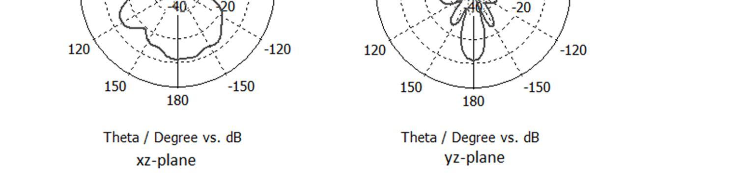
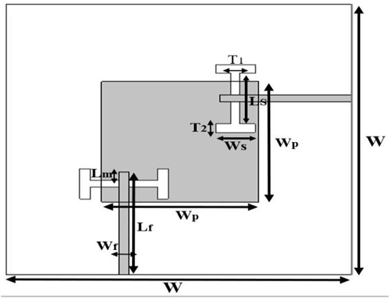
In this section, Single element dual polarized patch antenna for sub 6GHz 5G communication systems is presented A single element patch antenna is designed on Rogers RO4003C substrate with a dielectric constant =3 55, thickness of 0.8 mm, and loss tangent tan δ = 0. 0.0027. The geometry of the proposed antenna is shown in Fig. 1 where (a) shows the top view, (b) shows the side view of the antenna, and W is the antenna's length and width. The square patch is designed to achieve the same performance and results in the two ports of the(a)antenna.
A. Design Parameters
(b) Fig. 1 Dual polarized aperture coupled patch antenna structure (a) top view, and (b) side view.
The proposed antenna design is aimed to cover the N78 frequency band of sub 6 GHz 5G communication systems which is operating between 3.3GHz and 3.8GHz with 3.5GHz center frequency. In general, there are four popular methods to feed a microstrip antenna which are: microstrip line, coaxial probe, aperture coupling and proximity coupling. This paper selected the aperture coupled method to feed the antenna because it provides enough bandwidth to cover the N78 band, better isolation, and a large number of optimization parameters. The microstrip patch is printed on the upper metal layer, and the microstrip feed line is printed on the lower metal layer. The coupling between the patch and the feed line is conducted by inserting a slot on the ground plane; where H shaped has been used to provide a wideband characteristic with a shorter slot length compared to other shapes like rectangular shape, bowtie shaped, and hourglass shaped [12]. To achieve better performance for the antenna. H shaped parameters (Ws, Ls, T1, and T2) are considered in the design. A parametric optimization study using CST microwave studio 3D simulation is conducted to select the best values for H shaped parameters to achieve the best isolation, wider bandwidth, and efficient radiation Table I shows the optimized parameters of the proposed antenna.TABLE I Optimized parameters of single element patch antenna Parameters Description Value (mm)
W Width/length of the antenna 61.93 Wp Width/Length of the patch 28.11 Ws Width of the H slot 11.81 Ls Length of the H slot 7.04 T1 Thickness of the H slot center leg 1.55 T2 Thickness of the H slot side leg 1.98 Wf Width of the microstrip feed line 1.68 Lf Length of the microstrip feed line 21.15 Lm Length of the Stub 2.80 Off Patch offset in X/Y direction 10.00 T Thickness of the Patch 0.035 D1 Thickness of the upper substrate 0.80 D2 Thickness of the lower substrate 0.80 D3 Thickness of the Air 6.37
International Journal for Research in Applied Science & Engineering Technology (IJRASET) ISSN: 2321 9653; IC Value: 45.98; SJ Impact Factor: 7.538 Volume 10 Issue VIII Aug 2022 Available at www.ijraset.com 668©IJRASET: All Rights are Reserved | SJ Impact Factor 7.538 | ISRA Journal Impact Factor 7.894 | B. Simulation and Result
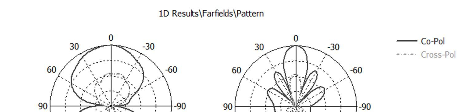
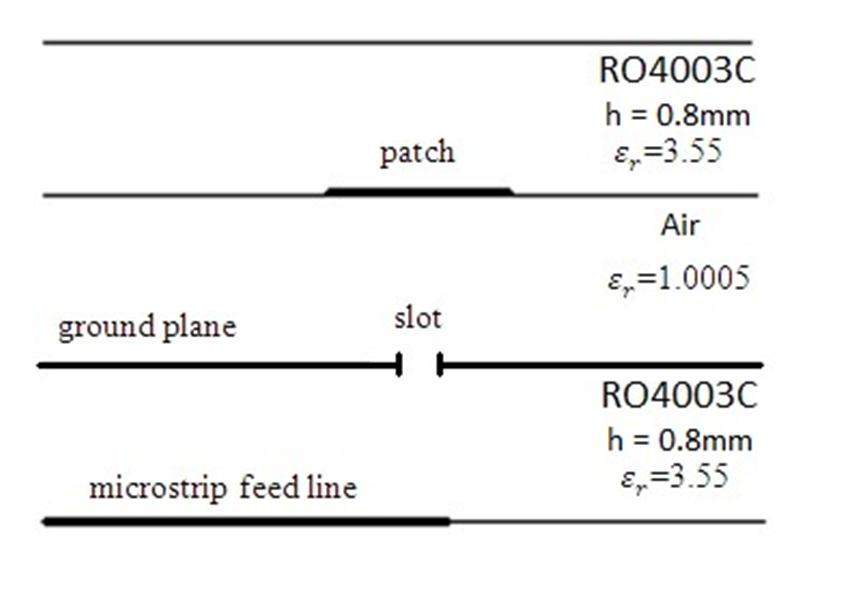
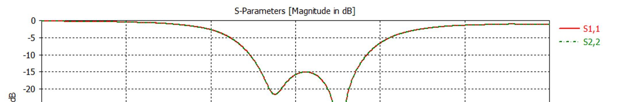
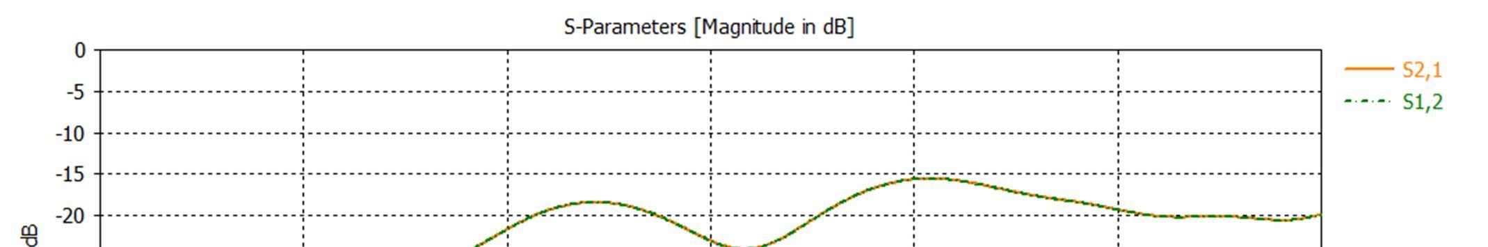
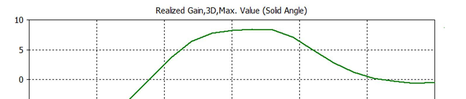
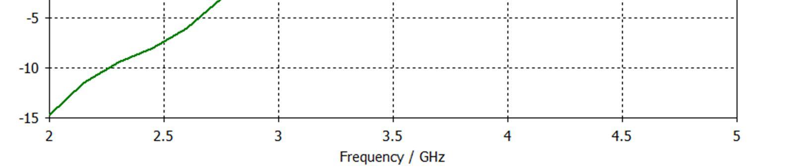
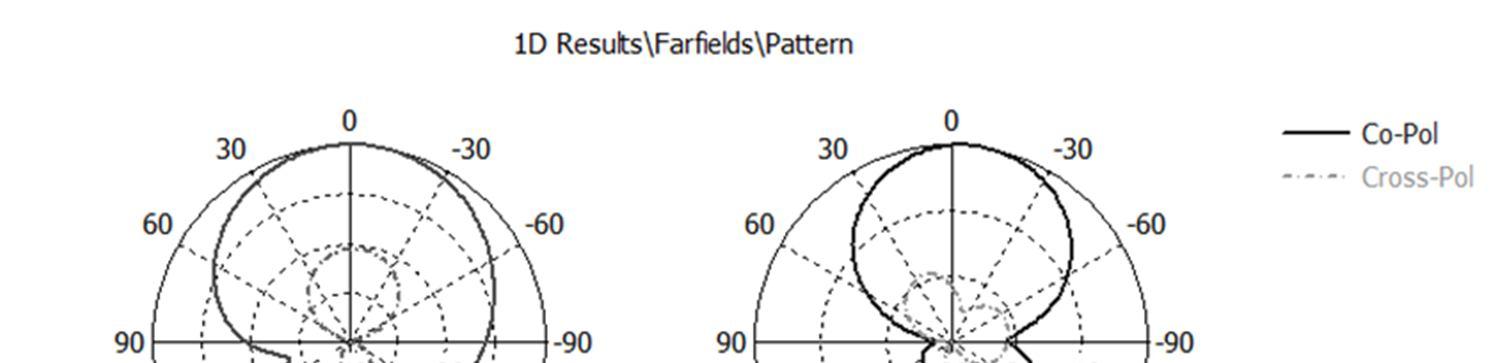
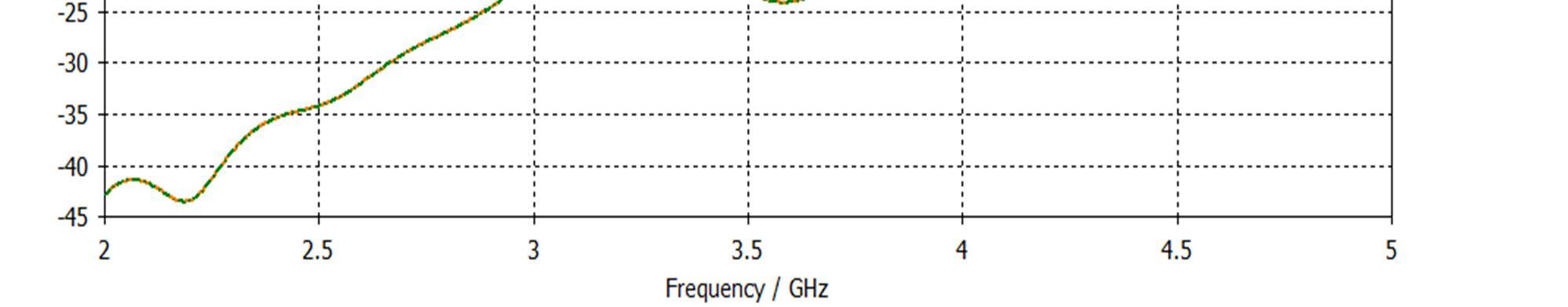
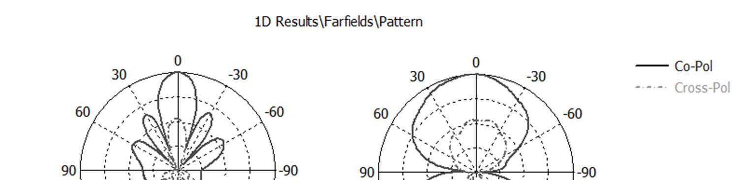
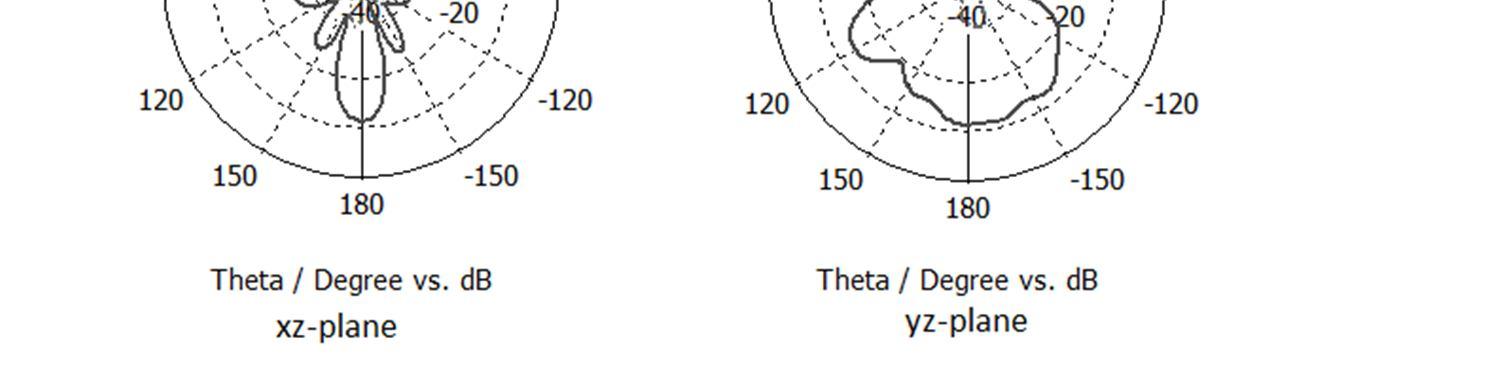
The single element simulation return loss Fig. 2 shows a good return loss with a 10 dB for both port1 and port2 having a bandwidth of 3.23 4.92 GHz which it is cover the N78 frequency band of the Sub 6GHz 5G communication systems. From Fig. 3 it can be observed that simulated isolation is better than 19 dB. From Fig. 4 It can be noticed that the maximum realized gain of the single element dual polarized antenna is 8.25 dB. The normalized co and the cross polarization radiation pattern is simulated and measured for both the horizontal plane (xz plane) and the vertical plane (yz plane) as shown in Fig. 5 and Fig. 6
Fig. 2 Return loss graph for S11 and S22 simulation result
Fig. 3 Isolation between Ports graph for S21 and S12 simulation result.
Fig. 4 Realized gain graph for simulation result.

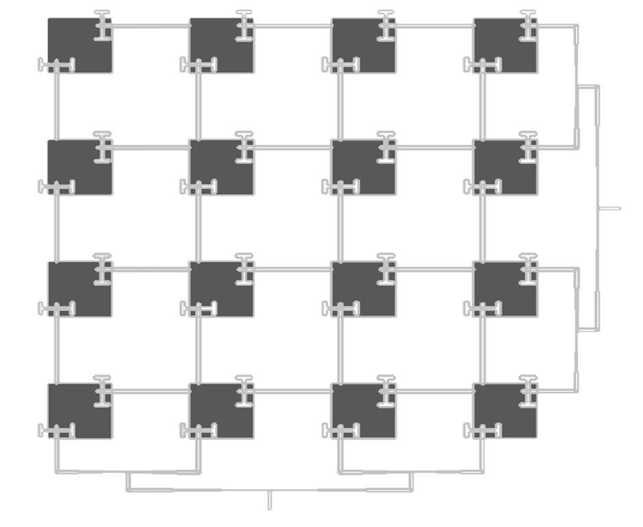
A 4x4 dual polarized patch antenna array is designed. The array's feeding network is first formed by corporate feeding of microstrip T junction power dividers and λ/4 impedance transformers to obtain 50Ω impedance at the input port of the array. Finally, the array's feeding network continues with series feeding where each patch feeds from the previous one. Hence, Series Corporate Feeding is used in the antenna array [13] The geometry of the proposed antenna array is shown in Fig. 7
Fig. 6 Radiation pattern of xz plane and yz plane for port2 DESIGN
Fig. 5 Radiation pattern of xyxz plane and yz plane for port1.
International Journal for Research in Applied Science & Engineering Technology (IJRASET) ISSN: 2321 9653; IC Value: 45.98; SJ Impact Factor: 7.538 Volume 10 Issue VIII Aug 2022 Available at www.ijraset.com 669©IJRASET: All Rights are Reserved | SJ Impact Factor 7.538 | ISRA Journal Impact Factor 7.894 |
III.ANTENNAARRAY
Fig. 7 4x4 dual polarized aperture coupled patch antenna array top view.
International Journal for Research in Applied Science & Engineering Technology (IJRASET) ISSN: 2321 9653; IC Value: 45.98; SJ Impact Factor: 7.538 Volume 10 Issue VIII Aug 2022 Available at www.ijraset.com 670©IJRASET: All Rights are Reserved | SJ Impact Factor 7.538 | ISRA Journal Impact Factor 7.894 |
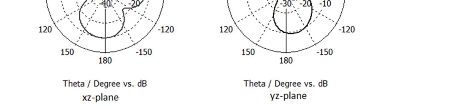
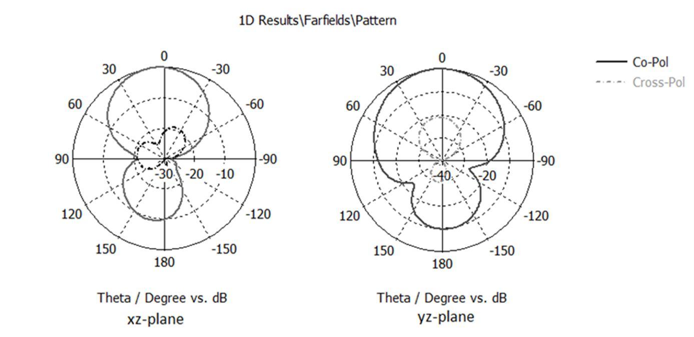
Fig. 10 Radiation pattern of xz plane and yz plane for port1 of the array
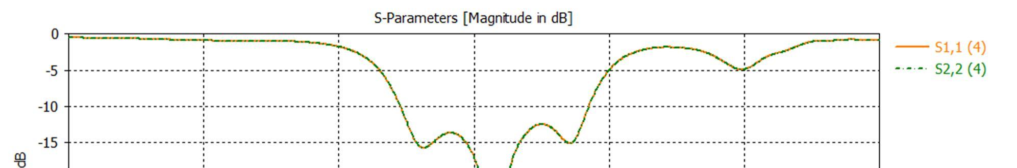
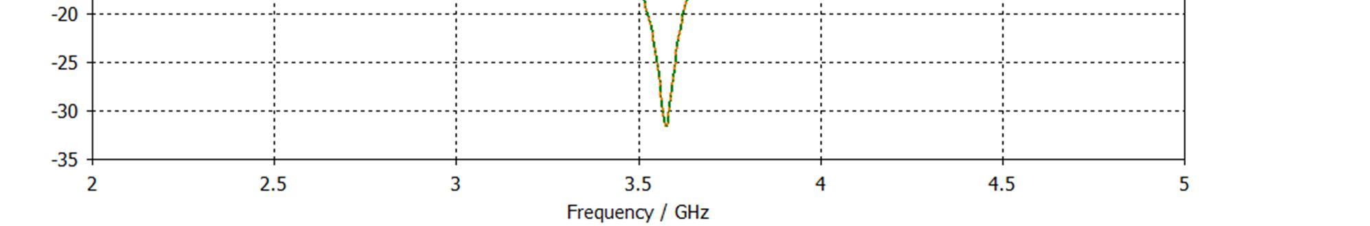
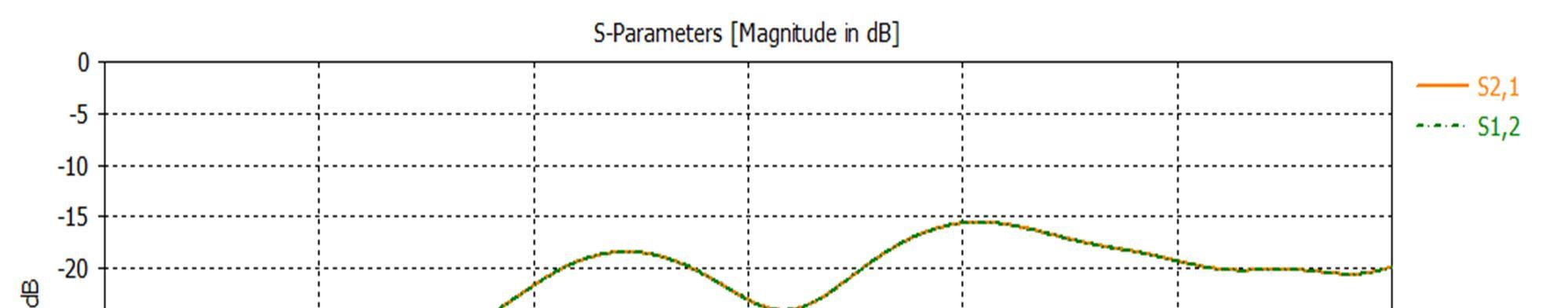
The simulated S11 and S22 of the array are presented in Fig. 8; from the figure, we can recognize that the array bandwidth achieved 18%, Fig. 9shows the isolation between the array's two ports, which is better than 32 dB Fig. 10 and Fig. 11. Represent the radiation pattern of the array for the two ports, and it can be noticed that the proposed array has a maximum simulated gain of 14.9 dB, and the half power beamwidth of the two ports is 49.5 degree and 17.8 degree in the xz plane and yz plane, respectively.
Fig. 8 Return loss graph for S11 and S22 simulation result for the antenna array
Fig. 9 Isolation between Ports graph for S21 and S12 simulation result for the antenna array
International Journal for Research in Applied Science & Engineering Technology (IJRASET) ISSN: 2321 9653; IC Value: 45.98; SJ Impact Factor: 7.538 Volume 10 Issue VIII Aug 2022 Available at www.ijraset.com 671©IJRASET: All Rights are Reserved | SJ Impact Factor 7.538 | ISRA Journal Impact Factor 7.894 |
Fig. 11 Radiation pattern of xz plane and yz plane for port2 of the array
A dual polarized H shaped aperture coupled 4x4 patch antenna array operating at N78 sub 6GHz is presented. The antenna array parameters have been optimized and simulated. The proposed antenna module exhibits a maximum realized gain of 14.9 dB, and isolation between ports of 32 dB. Also, good cross polarization levels for the design of the antenna are observed. The simulation shows that the antenna performance meets 5G base station system requirements.
IV.CONCLUSIONS
REFERENCES
[7] H. Jin, L. Zhu, H. Zou, Y. Luo, S. Xu, and G. Yang, “A Wideband Dual Polarized Antenna and Its Array With Electrically Downtilt Function for 5G Sub 6 GHz Communication Applications,” IEEE Access, vol. 8, pp. 7672 7681, Dec. 2019 [8] L. C. Paul, H. K. Saha, T. K. Roy, R. Azim, and M. T. Islam, “A Wideband Inset fed Simple Patch Antenna for Sub 6 GHz Band Applications,” in International Conference on Innovations in Science, Engineering and Technology (ICISET), 2022 [9] Z. Y. Yang, S. H. Mu, B. Yao, J. W. Wang, J. R. Qi, and X. M. Chen, “Dual Band High gain Photonic Crystal 5G Antenna with I slot for C band Applications,” in Photonics & Electromagnetics Research Symposium (PIERS), 2021 [10] L. Chang, and H. Liu, “Low Profile and Miniaturized Dual Band Microstrip Patch Antenna for 5G Mobile Terminals,” IEEE Transactions on Antennas and Propagation, vol. 70, pp. 2328 2333, Oct. 2021 [11] M Ikram, N Nguyen trong, and A M. Abbosh, “Common Aperture Sub 6 GHz and Millimeter Wave 5G Antenna System,” IEEE Access, vol. 8, pp. 199415 199423, Oct. 2020 [12] V Rathi, G. Kumar, and K. P. Ray, “Improved coupling for aperture coupled microstrip antennas,” IEEE Transactions on Antennas and Propagation vol. 44, pp 1196 1198, August 1996 [13] T. Khalifa, N Ramli, and N. M Sahar, “Microstrip Array Antenna using Series Corporate Feed for Navigation System,” Indonesian Journal of Electrical Engineering and Informatics (IJEEI), vol. 8, pp. 571 524, Oct 2020
[1] J A. Adebusola, A A. Ariyo, O. A. Elisha, A. M. Olubunmi, and O. O. Julius, “An Overview of 5G Technology,” in International Conference in Mathematics, Computer Engineering and Computer Science (ICMCECS), 2020 [2] O O. Erunkulu, A M. Zungeru, C K. Lebekwe, M Mosalaosi, and J. M. Chuma, “5G Mobile Communication Applications: A Survey and Comparison of Use Cases,” IEEE Access, vol. 9, pp. 97251 97295, June 2021 [3] J. H L. Thi, S X Ta, X Q Nguyen, K K Nguyen, and C H Ngoc, “Design of compact broadband dual polarized antenna for 5G applications,” in international journal of RF and microwave computer aided engineering, vol. 31, issue 5, May 2021 [4] H. Li, X. Li, Y. Li, X. Du, and Y. Zhang, “A Wideband Dual Polarized Filtering Antenna for 5G Sub 6 GHz Base Station Applications,” in 13th International Symposium on Antennas, Propagation and EM Theory (ISAPE), 2021 [5] Z. Gu, Y. Zhang, and Q. Li, “A Dual Band Dual Polarized Base Station Antenna for Sub 6 GHz 5G Communications,” in 9th Asia Pacific Conference on Antennas and Propagation (APCAP), 2021 [6] M Alibakhshikenari, B S. Virdee, C H See, P. Shukla, S. M. Moghaddam, A. U. Zaman, S. S. M. O. Akinsolu, B. Liu, J. Yang, R. Abd Alhameed, F. Falcone, and E Limiti, “Dual Polarized Highly Folded Bowtie Antenna With Slotted Self Grounded Structure for Sub 6 GHz 5G Applications,” IEEE Transactions on Antennas and Propagation, vol. 70, pp. 3028 3033, Oct 2021