
10 VII July 2022 https://doi.org/10.22214/ijraset.2022.45934

Keywords: Shear wall, Seismic load, Structure Health Monitoring, Response Spectrum, Wind load.
I. INTRODUCTION
In recent decades, due to a lack of adequate construction sites, tall buildings have been the dominant means of accommodation and places of business in metropolises where economy and population grows fast. Compared to ordinary buildings, tall buildings are more densely populated, resulting in a bigger impact on the economy. In seismically prone areas, such as San Francisco, Tokyo and Istanbul, the safety of such buildings should be known prior to an earthquake and any damage due to the earthquake should be detected. To meet such necessities, tall building initiatives have been active especially in California to establish a framework for the selection of input motions, modelling approaches and performance criteria (Moehle, 2007). Structural Health Monitoring (SHM) systems allow us to understand the dynamic characteristics of the buildings. SHM systems are based on data acquisition systems consisting of acceleration sensors and data recorders. Based on the ambient vibration data records, the dynamic characteristics of a building such as modal periods, shapes and damping ratios can be determined. Taking those characteristics into account, the existence of any damage and verification of design assumptions can be determined. In addition, the finite element model (FEM) of the building can be updated to represent the true behaviour of the building. Californian seismic design guidelines recommend SHM systems to be installed on tall buildings as these systems make crucial contributions to the understanding of the dynamic behaviour of buildings and enhance the capability of engineers for damage detection More and more people are shifting to bigger cities for better lifestyle and easy livelihood. This causes concentration of population in cities. Constant effort is being made to find habitable land. As habitable land is constant and not increasing to meet the ever growing demands of increasing population in cities.
Abstract: Structural health monitoring techniques have been utilized to inspect the current conditions of structures, as well as their post earthquake performances. The dynamic characteristics of a building, such as modal periods, shapes and damping ratios can be obtained by analysing the ambient vibration data. It is well known that dynamic characteristics generated from the finite element model (FEM) and vibration data, even for the intact building, show remarkable differences. Assumptions made in the FEM are one of the main reasons for those differences. To examine feasible solutions to such problems mentioned above Here an attempt has been made to study the behaviour of different structures of reinforced concrete with different heights with and without shear walls. Coupled shear walls have also been studied to understand the comparative merit or demerit of framed structures with shear wall structures. Studies have been carried out on sample model structures and analysis has been carried out by ETABS software. It has been ensured to consider sample models that represent the current practices in structural design to include different structural configurations. Models having varied structural configurations like framed, shear wall, coupled shear wall, central core shear wall, core in core etc. have been taken into consideration. The inherent asymmetry present in the structures have also been dealt. Natural frequencies and mode shapes of the structure were determined by frequency domain decomposition method. In addition, identification of damping was performed due to the fact that damping ratio plays a significant role in the magnitude of inter-story drift during an earthquake. The FEM of the structure was constructed based on design drawings and updated to represent the real mode shapes and frequencies of the structure. By using the updated FEM with standard damping ratio in Indian Earthquake Code and the identified damping ratio, seismic performance assessment of the building for a possible earthquake. High rise building structures are both a necessity and a matter of sophistication and pride for structural engineers. Buildings crossing 25 to 30 storeys are a common phenomenon these days. But what happens to a structure as it crosses these height limits? Forces of nature in the form of earthquakes and cyclones starts playing brutal games with the structures. Higher the structure goes; higher it attracts the forces and wrath of nature in the form of seismic force.
1M. Tech (Structural & Foundation Engineering), Department of Civil Engineering AL FALAH University, Faridabad, INDIA 2(Assistant Professor), Department of Civil Engineering AL FALAH University, Faridabad, INDIA
Analytical Structural Health Monitoring of Shear Wall Building Md Naseem Rangrez 1, Misbah Danish Sabri 2
International Journal for Research in Applied Science & Engineering Technology (IJRASET) ISSN: 2321 9653; IC Value: 45.98; SJ Impact Factor: 7.538 Volume 10 Issue VII July 2022 Available at www.ijraset.com 4185©IJRASET: All Rights are Reserved | SJ Impact Factor 7.538 | ISRA Journal Impact Factor 7.894 |


Following six types of models have been considered for analysis. It was attempted to choose models that are representative of actual building types that are being constructed nowadays. Type A is regular framed structure with columns. Type B hybrid framed structure with shear wall in periphery and columns. Type C hybrid framed structure with shear wall in centre and columns. Type D is tube structure. Type E is hybrid framed structure with lift core in centre. Type F is tube in tube system.
Following are the main objectives of the work:
Horizontal growth is not possible. This leaves us with only option, rise vertically. This gives rise to tall high rise structures. High rise building structures are both a necessity and a matter of sophistication and pride for structural engineers. Buildings crossing 25 to 30 storeys are a common phenomenon these days. But what happens to a structure as it crosses these height limits? Forces of nature in the form of earthquakes and cyclones starts playing brutal games with the structures. Higher the structure goes; higher it attracts the forces and wrath of nature in the form of seismic force. Seismic force, predominantly being an inertia force depends on the mass of the structure. As the mass of the structure increases the seismic forces also increase causing the requirement of even heavier sections to counter that heavy forces. And these heavy sections further increase the mass of the structure leading to even heavier seismic forces. Structural designers are met with huge challenge to balance these contradictory physical phenomena to make the structure safe. The structure no more can afford to be rigid. This introduces the concept of ductility. The structures are made ductile, allowing it yield in order to dissipate the seismic forces. A framed structure can be easily made ductile by properly detailing of the reinforcement. But again, as the building height goes beyond a certain limit, these framed structure sections (columns) get larger and larger to the extent that they are no more practically feasible in a structure. There comes the role of shear walls. Shear walls provide ample amount of stiffness to the building frame resisting loads through in plane bending. But they inherently make the structure stiffer. So, there must be a balance between the amount of shear walls and frame elements present in a structure for safe and economic design of high rise structures.
II. OBJECTIVE
2) Comparison of behavior of different structures of reinforced concrete with different heights, with and without shear walls.
III. MODELS CONSIDERED FOR ANALYSIS
3) Coupled shear walls have also been studied to understand the comparative merit or demerit of framed structures with shear wall structures.
International Journal for Research in Applied Science & Engineering Technology (IJRASET) ISSN: 2321 9653; IC Value: 45.98; SJ Impact Factor: 7.538 Volume 10 Issue VII July 2022 Available at www.ijraset.com 4186©IJRASET: All Rights are Reserved | SJ Impact Factor 7.538 | ISRA Journal Impact Factor 7.894 |
1) Comparison of Effects of Seismic & Wind Forces on High Rise Buildings with different structural configuration and to compare the key parameters.

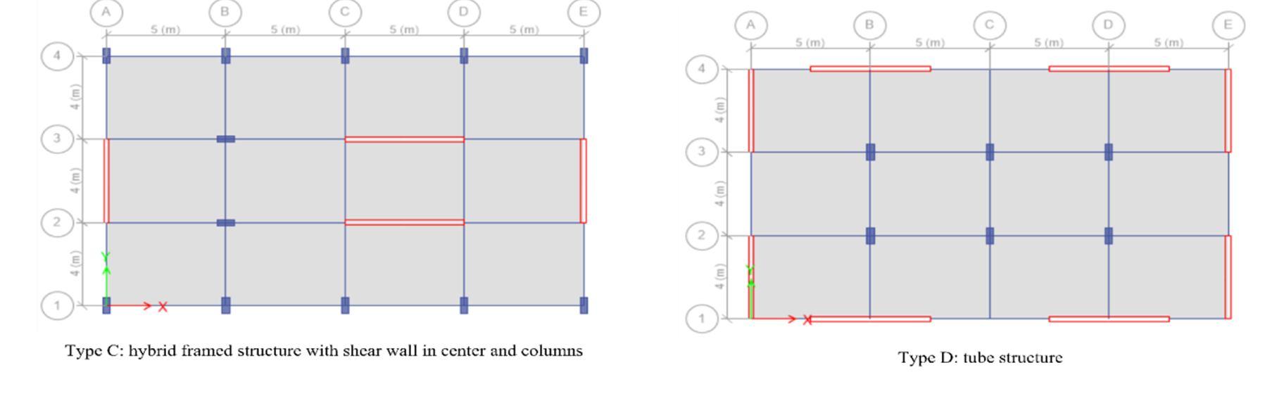
International Journal for Research in Applied Science & Engineering Technology (IJRASET) ISSN: 2321 9653; IC Value: 45.98; SJ Impact Factor: 7.538 Volume 10 Issue VII July 2022 Available at www.ijraset.com 4187©IJRASET: All Rights are Reserved | SJ Impact Factor 7.538 | ISRA Journal Impact Factor 7.894 | Fig:1 Models Considered IV. STATIC AND DYNAMIC PARAMETERS 1) Design Parameters: Here the Analysis is being done for G+10, G+25, G+35, G+50, (rigid joint regular frame) building by computer software using ETABS. 2) Design Characteristics: The following design characteristics are considered for Multistorey rigid jointed frames Table 1 Design Data of RCC Frame Structures S.No Particulars Dimension/Size/Value 1. Model G+10, G+25, G+35, G+50 2. Seismic Zones IV 3. Floor height 3M 4. Basement 4M 5. Building height 41.6m,86.6m,113.6m & 161.6m 6. Plan size 20mx12m 8. Size of columns 0.3mx0.75m 9. Size of beams 0.3mx0.75m &0.3mx0.6m 10 Shear Walls 0.23m 11. Thickness of slab 125mm 12. Earthquake load As per IS 1893 2002 13. Type of soil Type II, Medium soil as per IS 1893 14. Ec 5000√fck N/ mm2(Ec is short term static modulus of elasticity in N/ mm2) 15. Fck 0.7√fc k N/ mm2(Fck is characteristic cube strength of concrete in N/ mm2 16. Live load 2 kN/ m2 17. Floor finish 1.00kN/ m2 18. Services 1.00kN/ m2 19 Specific wt. of RCC 25.00 kN/ m2 20. Specific wt. of infill 20.00 kN/ m2 21. Material used Concrete M 25, M 30and Reinforcement Fe 500(HYSD Confirming to IS 1786)


International Journal for Research in Applied Science & Engineering Technology (IJRASET) ISSN: 2321 9653; IC Value: 45.98; SJ Impact Factor: 7.538 Volume 10 Issue VII July 2022 Available at www.ijraset.com 4188©IJRASET: All Rights are Reserved | SJ Impact Factor 7.538 | ISRA Journal Impact Factor 7.894 | A. Seismic Load As per IS: 1893, Noida is located in Seismic Zone IV. Design base shear, V = Z I W Sa/2 R g The values of the salient coefficients are tabulated below: Table 2 Seismic parameters Sl. Description Value Reference 01 Seismic Factor for Zone: IV 0.24 IS 1893 02 Structure importance 1.0 IS 1893 coefficient, I. 03 Response reduction factor, R 5.00 IS 1893 04 Damping 5% IS 1893 05 Time period Variable IS 1893 B. Wind Load The wind velocity at Delhi is 47m/s. The other parameter of wind load as per IS: 875 (Part 3) is summarized below: Table 3 Wind parameters Sl. Description Value Reference 01 Terrain category. 3 IS 875 02 Class of structure. C IS 875 03 Probability factor, k1. 1.0 IS 875 04 Terrain, height and structure size factor, k2. As/Height IS 875 05 Topography factor, k3. 1.0 IS 875 V. ANALYSIS RESULTS AND DISCUSSIONS The analysis of different models of varying heights produced a large set of data. Microsoft excel was used for tabulation plotting and analysis of results obtained by ETABS analysis. The first objective was to figure out the key parameters that affected the building. Tabulation was done for different key parameters for all the models. A sample tabulation has been shown below for Type A structures having 10 storeys. Looking at most of the curves above it is evident that Wind plays a vital role in the behaviour of the building, especially when going beyond 10 storeys. It is clearly seen that the response of almost all types of building shows critical for earthquake loads for buildings up to 10 storeys and not wind loads. But we go beyond 10 storeys the response due to wind load starts exceeding the response due to earthquake loads. The similar trend can be seen for structures in the 25 storey range. For structures in the range of 35 and 50 storeys, wind loads clearly are the governing cases. A. Comparison of 25 Storey Buildings Base Reaction Table 4 Base Reaction Case/ComboLoad FX FY FZ MX MY MZ kN kN kN kN m kN m kN m Dead 0 0 48022.89 288137.3 480229 0 Live 0 0 6060 36360 60600 0 EQX 1290.55 0 0 0 40514.6 7743.301 EQY 0 1290.55 0 40514.62 0 12905.5 SPECX Max 629.9654 1.02E 05 0 1.53E 05 16214.81 3779.792 SPECY Max 1.22E 05 669.8013 0 17147.68 3.33E 05 6698.013 WIND 1 697.436 0 0 0 16667.3 4184.614 WIND 2 0 1162.39 0 27778.88 0 11623.9
International Journal for Research in Applied Science & Engineering Technology (IJRASET) ISSN: 2321 9653; IC Value: 45.98; SJ Impact Factor: 7.538 Volume 10 Issue VII July 2022 Available at www.ijraset.com 4189©IJRASET: All Rights are Reserved | SJ Impact Factor 7.538 | ISRA Journal Impact Factor 7.894 | Modal Period Table 5 Modal Period Case Mode Period Frequency Circular Frequency Eigenvalue sec cyc/sec rad/sec rad²/sec² Modal 1 2.317 0.432 2.7117 7.3532 Modal 2 2.164 0.462 2.903 8.4274 Modal 3 1.85 0.541 3.3961 11.5333 Modal 4 0.715 1.398 8.7818 77.1202 Modal 5 0.665 1.503 9.4418 89.1483 Modal 6 0.575 1.74 10.9297 119.4573 Modal 7 0.398 2.513 15.7911 249.3589 Modal 8 0.356 2.81 17.6571 311.7744 B. Comparison of 25 Storey Buildings Base Shear Table 6 Base Shear Base Shear (kN) Load Type A Type B Type C Type D Type E Type F EQX 1290.55 1560.97 717.63 1542.54 1914.97 1000.23 EQY 1290.55 1560.97 717.63 1542.54 1914.97 1000.23 SPECX 629.9654 954.4855 595.0223 574.9217 1311.5169 1184.827 SPECY 669.8013 935.0808 548.095 876.7248 1172.8936 975.8446 Fig:2 Comparison of Base shear and Modal period for 25 Storey Buildings

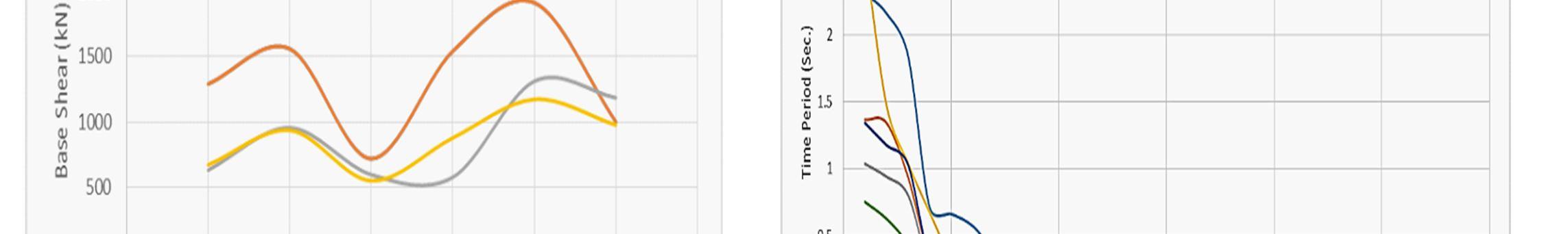
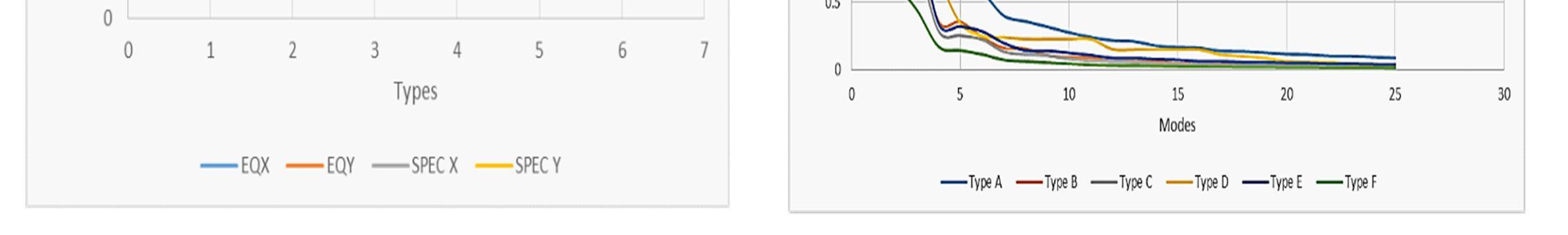
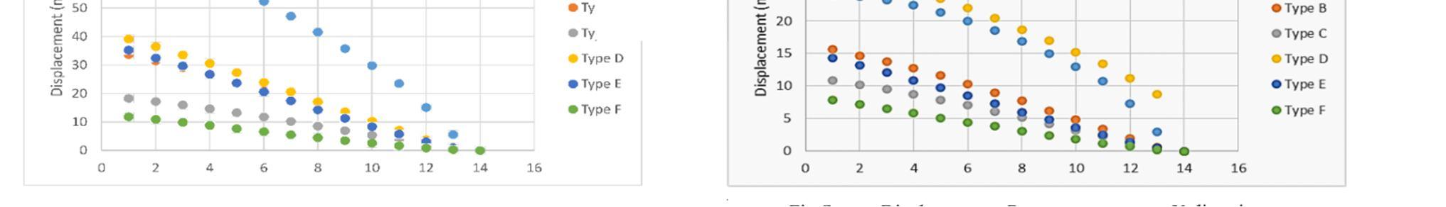
International Journal for Research in Applied Science & Engineering Technology (IJRASET) ISSN: 2321 9653; IC Value: 45.98; SJ Impact Factor: 7.538 Volume 10 Issue VII July 2022 Available at www.ijraset.com 4190©IJRASET: All Rights are Reserved | SJ Impact Factor 7.538 | ISRA Journal Impact Factor 7.894 | Fig:3 Comparison of storey displacement period for 25 Storey Buildings C. Comparison of 50 Storey Buildings 1) Modal Period Table 7 Comparison of Modal period 50 Storey Buildings Period (Sec.) Case Mode Type A Type B Type C Type D Type E Type F Modal 1 16.128 10.994 14.041 9.929 13.955 6.483 Modal 2 12.347 8.467 9.141 9.394 9.071 4.307 Modal 3 8.316 5.18 6.552 5.539 4.205 2.432 Modal 4 3.578 2.585 2.898 2.573 2.728 1.501 Modal 5 3.395 2.346 2.458 2.36 2.259 1.173 Modal 6 2.539 1.568 1.948 1.602 1.371 0.74 Modal 7 1.773 1.225 1.347 1.229 1.203 0.665 Modal 8 1.739 1.189 1.228 1.144 1.055 0.552 Modal 9 1.434 0.835 1.038 0.813 0.811 0.39 Modal 10 1.229 0.774 0.859 0.735 0.721 0.385

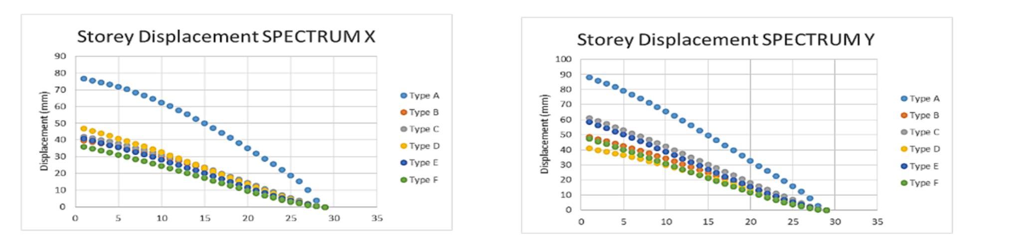
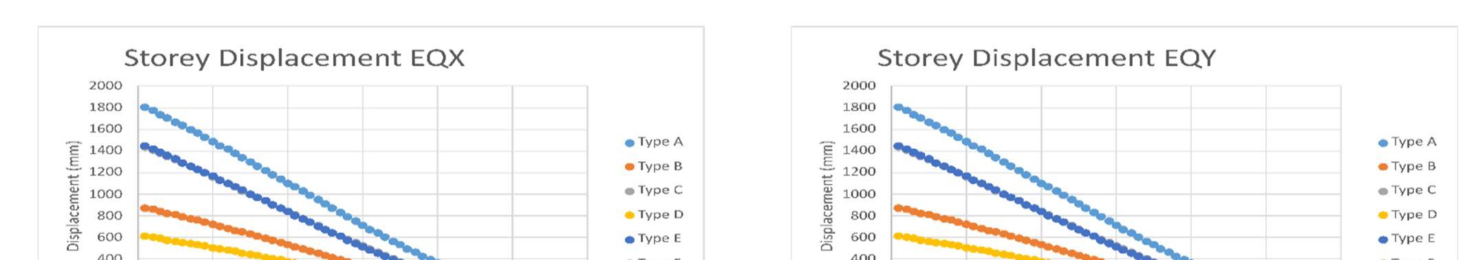
International Journal for Research in Applied Science & Engineering Technology (IJRASET) ISSN: 2321 9653; IC Value: 45.98; SJ Impact Factor: 7.538 Volume 10 Issue VII July 2022 Available at www.ijraset.com 4191©IJRASET: All Rights are Reserved | SJ Impact Factor 7.538 | ISRA Journal Impact Factor 7.894 | Base Shear (kN) Load Type A Type B Type C Type D Type E Type F EQX 2438.884 2352.892 2390.501 2321.685 2889.0486 1472.083 EQY 2438.884 2352.892 2390.501 2321.685 2889.0486 1472.083 XSPEC 1329.422 1301.593 1306.518 1904.936 1612.8568 979.9861 YSPEC 1258.852 1262.631 1248.717 1909.054 1539.8733 933.4433 Fig: 4 Comparison of storey displacement period for 50 Storey Buildings VI. CONCLUSIONS
The choice of any particular type of structure will ultimately depend upon the storey range, type of materials available, architectural requirements, functional use and the economy involved. Looking at most of the comparisons with Wind forces, it is evident that Wind plays a vital role in the behaviour of the building, especially when going beyond 10 storeys. It is clearly seen that the response of almost all types of building shows critical for earthquake loads for buildings up to 10 storeys and not wind loads. But we go beyond 10 storeys the response due to wind load starts exceeding the response due to earthquake loads. The similar trend can be seen for structures in the 25 storey range. For structures in the range of 35 and 50 storeys, wind loads clearly are the governing cases. The response is way more than the earthquake loads. The approach for design of structures for wind and earthquake are diagonally apart. Wind forces are generally push forces that tries to topple or bend the structure vertically. They are applicable on the exposed face of the structures. In order to safeguard the structure for wind, one very simple solution can be to make the structure heavier. Heavier the structure, better its ability to resist wind forces. The approach for design of structures for wind and earthquake are diagonally apart. Wind forces are generally push forces that tries to topple or bend the structure vertically. They are applicable on the exposed face of the structures. In order to safeguard the structure for wind, one very simple solution can be to make the structure heavier. Heavier the structure, better its ability to resist wind forces.


[9] Bagheri Bahador, Firoozabad Salimi Ehsan, and Yahyaei Mohammadreza (2012) “Comparative Study of the Static and Dynamic Analysis of Multi Storey Irregular Building”
[11] Shahzad Jamil Sardar and Umesh. N. Karadi (2014) “effect of change in shear wall Location on storey drift of multistorey building subjected to lateral loads”
International Journal for Research in Applied Science & Engineering Technology (IJRASET) ISSN: 2321 9653; IC Value: 45.98; SJ Impact Factor: 7.538 Volume 10 Issue VII July 2022 Available at www.ijraset.com 4192©IJRASET: All Rights are Reserved | SJ Impact Factor 7.538 | ISRA Journal Impact Factor 7.894 |
[1] Datta. T. K Seismic analysis of structures, John Wiley & Sons (Asia) Pte ltd, 2010 [2] Chopra A K, Dynamics of Structures [3] Jain. S K, IIT Roorkee Review of Indian seismic code, IS 1893 (Part 1): 2002 [4] Reddy K. R. C. Sandip A. Tupat (2012). “The effect of zone factors on wind and earthquake loads of high rise structures”
But earthquake forces are totally different. They are basically inertia forces, which depend on the mass of the structures. The structures on action of earthquake forces rarely topple over or fall down. They actually collapse just under its own vertical axis. Since earthquake forces depend upon the weight/mass of the structure, heavier the structure, more earthquake force it attracts. The idea is to make the structure lighter. Lighter the structure, better it is for the structure to resist earthquake forces But earthquake forces are totally different. They are basically inertia forces, which depend on the mass of the structures. The structures on action of earthquake forces rarely topple over or fall down. They actually collapse just under its own vertical axis. Since earthquake forces depend upon the weight/mass of the structure, heavier the structure, more earthquake force it attracts. The idea is to make the structure lighter. Lighter the structure, better it is for the structure to resist earthquake forces. Structures within 10 storey are generally governed by earthquake loads and wind does not play a vital role. Generally, in this range type A framed are preferred over shear wall structures. Provision of shear walls with lift core as given in Type C are also common. But here the shear walls alone do not impact the lateral stability of the structures considerably. Tube structures and tube in tube structures are not required in this height zone. They are often less economical than simple framed structures.in general hybrid structures with combinations of shear walls and columns are provided. The economy of the structures often depends upon the relative presence of shear walls and columns in appropriate ratios. Overall, it can be concluded that framed structures are economical for structures below 10 storeys. Structures in the range of 25 storey are supposed to be sufficiently ductile to dissipate higher level of base shear but just enough stiffness not to attract seismic forces. Type A framed structures can be constructed but it is often seen that the section requirement at the bottom storey is very high this causes accessibility issues as often parking is planned at these levels. Coupled shear wall structures & hybrid structures with shear walls at center and periphery are best suited for this storey range. Tube structures and tube in tube structures are not required here here also the economy of the structures often depends upon the relative presence of shear walls and columns in appropriate ratios. Overall, it can be concluded that hybrid structures with shear walls at center and periphery are best Structuressuited.inthe
REFERENCES
[13] Anshuman. S, Dipendu Bhunia, Bhavin Ramjiyani (2011) “Solution of Shear Wall Location in Multi Storey Building” [14] Seyed M. Khatami, Alireza Mortezaei & Rui C. Barros (2012) “Comparing Effects of Openings in Concrete Shear Wallsunder Near Fault Ground Motions”
[10] Sharma Mohit & Maru Savita (2011) “Dynamic Analysis of Multistoried Regular Building”
range of 35 storey are expected to vibrate in higher modes of vibrations and the effect of higher modes of vibration often causes the lateral load resisting elements requiring huge sections at middle half of the building. consequently, the columns size requirements at the bottom storeys does not remain feasible at all. However, hybrid structures with shear walls at center and periphery can be constructed but the requirement of shear walls is enhanced which further causes increase in base shear. so, the sections required for shear walls also are very high at the bottom storey. additionally, presence of too many shear walls to tackle huge base shear causes the structures to be very rigid which in itself is not a desirable feature. Tube and tube in tube structures are suitable for this storey range. Structures in the range of 50 and above stories are expected to vibrate in even higher modes of vibration. This causes the use of simple framed, or simple shear wall structures practically impossible to design. We have to go for innovative structural configurations like braced shear walled framed structures, tension structures, pretension structures etc. No particular structural configuration can be assumed to behave satisfactorily in this storey range. Tube and Tube in Tube structures with spandrel beams may prove to be useful, but the decision of the structural configuration depends on the structure at hand. Engineering judgement, innovation and practical application should be the guiding factors for these structures. To be able to balance, these two contradictory principles of design is a real challenge for structural engineers.
[12] Yousuf Mohammed & shimpale P.M. (2013) “Dynamic Analysis of Reinforced Concrete Building with Plan Irregularities”
[5] Jain. S K and Navin C Nigam “Historical developments and current status of Earthquake Engineering in India [6] Mohapatra, A.K. & Mohanty, W.K. “An Overview of Seismic Zonation Studies in India” [7] Dean Kumar B. & Swami B.L.P. “Wind effects on tall building frames influence of dynamic parameters” [8] Varalakshmi V., Shiva Kumar G., Sunil Sarma R. (2014) “Analysis and Design of G+5 Residential Building”