

Analysis of Cable Stayed Bridge and Girder Bridge Considering Seismic Forces and I.R.C. Loading
Prince Kumar1, Deepak Bandewar2, Sachin Jat3 Department of Civil Engineering SIRTS BhopalAbstract: A bridge is a structure which is built over some physical obstacles such as a body of water, valley, road and railway, its purpose is to provide crossing over that obstacle. Numerous bridges are in exist namely Arch Bridge, Girder Bridge, Suspension bridge, Cable stayed Bridge, etc. Design of bridges varies depending on the function of the bridge, the nature of the terrain where the bridge is constructed and anchored, the funds available to build it. Structural analysis is a process to analyze a structural system to predict its responses and behaviour by using physical laws and mathematical equations. The main objective of structural analysis is to determine internal forces, stresses and deformation of structure under various load effects. In the present work, Girder Bridge and Cable stayed bridge are modelled and comparative analysis is carried out for dynamically loading conditions. A comparison is made between the bridges for dead load, live load and combined load.
Keywords: Structural Analysis, Bridge, seismic, vehicular load,

I. INTRODUCTION

A bridge is a structure built to span a physical obstacle, such as a body of water, valley, or road, without closing the way underneath. It is constructed for the purpose of providing passage over the obstacle, usually something that is otherwise difficult or impossible to cross. There are many different designs that each serve a particular purpose and apply to different situations. Designs of bridges vary depending on the function of the bridge, the nature of the terrain where the bridge is constructed and anchored, the material used to make it, and the funds available to build it.
A. Girder Bridge
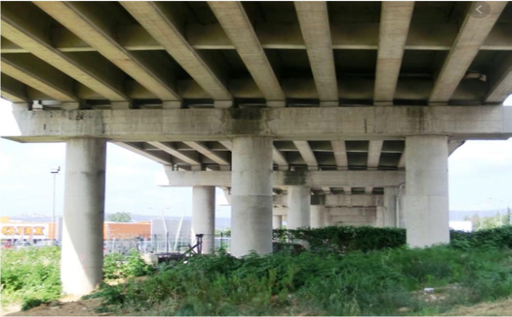
In Girder Bridge the deck slab is supported by means of girders. The girder may be of rolled steel girder or plate girder or box girder. In case of Girder Bridge, the deck slab is supported by means of girders. The girder may be of rolled steel girder or plate girder or box girder. Load coming from the deck are taken by girder and transferred them to the piers and abutments. A beam may be made of concrete or steel. Many shorter bridges, especially in rural areas where they may be exposed to water overtopping and corrosion, utilize concrete box beams. The term "girder" is typically used to refer to a steel beam. In a beam or girder bridge, the beams themselves are the primary support for the deck, and are responsible for transferring the load down to the foundation. Material type, shape, and weight all affect how much weight a beam can hold. Due to the properties of inertia, the height of a girder is the most significant factor to affect its load capacity. Longer spans, more traffic, or wider spacing of the beams will all directly result in a deeper beam. In truss and arch style bridges, the girders are still the main support for the deck, but the load is transferred through the truss or arch to the foundation.
ISSN: 2321 9653; IC Value: 45.98; SJ Impact Factor: 7.538 Volume 10 Issue IX Sep 2022 Available at www.ijraset.com

B. Cable Stayed Bridge
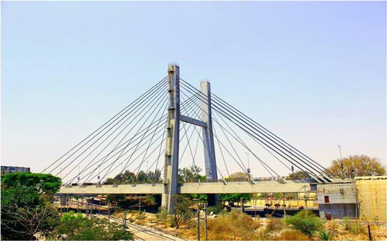
A cable stayed bridge has one or more towers (or pylons), from which cables support the bridge deck. A distinctive feature is the cables which run directly from the tower to the deck, normally forming a fan like pattern or a series of parallel lines. This is in contrast to the modern suspension bridge, where the cables supporting the deck are suspended vertically from the main cable, anchored at both ends of the bridge and running between the towers. The cable stayed bridge is optimal for spans longer than cantilever bridges and shorter than suspension bridges. This is the range where cantilever bridges would rapidly grow heavier if the span were lengthened, while suspension bridge cabling would not be more economical if the span were shortened.
C. Objectives of the Study

1) To understand The Behavior of Girder and cable stayed bridge under vehicular loading.
2) To determine the effect of seismic loading over long span bridge structures.
3) To perform Analysis of the structure considering vehicular and lateral loading using SAP2000.
4) To perform stability check and cost analysis of both the structures.
II. LITERATURE SURVEY
Khawaja Ali et.al (2021) the examination paper introduced a correlation of link remained and extradosed spans dependent on the security appraisal of their visit links completed on the wellbeing variables of stay links under exhaustion and extreme breaking point states by thinking about the impacts of different untoward and harming factors, for example, over burdening, link misfortune, and erosion. The essential objective of the exploration was to depict the primary incongruities between the two kinds of extensions and assess their underlying redundancies by utilizing deterministic and non deterministic strategies. To accomplish this objective, three dimensional limited component models of the two extensions were created dependent on the current plan rules for stay links in Japan. After the reasonable conditions of the extension models were accomplished, static examinations were performed for various wellbeing elements of stay links in a parametric way. At long last, the main request unwavering quality strategy and Monte Carlo technique were applied to decide the dependability list of stay links.
The investigation results show that link remained and extradosed spans display diverse primary redundancies for various security factors under similar stacking conditions. Additionally, a huge expansion in underlying excess happens with a steady expansion in the safety variables of stay cables.
Priyanka Rajput et.al (2020) the research paper conducted comparative study of cable stayed bridge using SAP2000 software and the material of deck girder of bridges was changed and comparison was done on the basis of shear force, bending moment, torsion, bending stress of girders with concrete and steel and prestressed girder of same span and same loading conditions. Economic aspect of cable stayed bridge with concrete steel and prestressed deck girder was even further investigated. Maximum stresses, shear forces, bending moment was compared for 120.0m span concrete, steel and prestressed bridge girder. Concrete deck girder M 60 grade of concrete was used in design of cable stayed bridge and for design of steel girder bridges FE 500 was used in design of cable stayed bridge. Different combination of dead, live, earthquake and prestressing are taken into account in all the models of cable stayed bridge design.
ISSN: 2321 9653; IC Value: 45.98; SJ Impact Factor: 7.538 Volume 10 Issue IX Sep 2022 Available at www.ijraset.com

III. METHODOLOGY
Here comparative Analysis was done one a cable stayed bridge and girder bridge in the examination program SAP 2000 in which joints interface is checked and improved, and IRC Class AA and seismic load are considered.
Two cases have been considered for near examination
1) Girder Bridge
2) Cable Stayed Bridge
The accompanying two cases must be examined and contrasted with set up a near report
Planning of calculation and sectional properties in SAP 2000.


b) Relegating sections according to Indian standard steel.
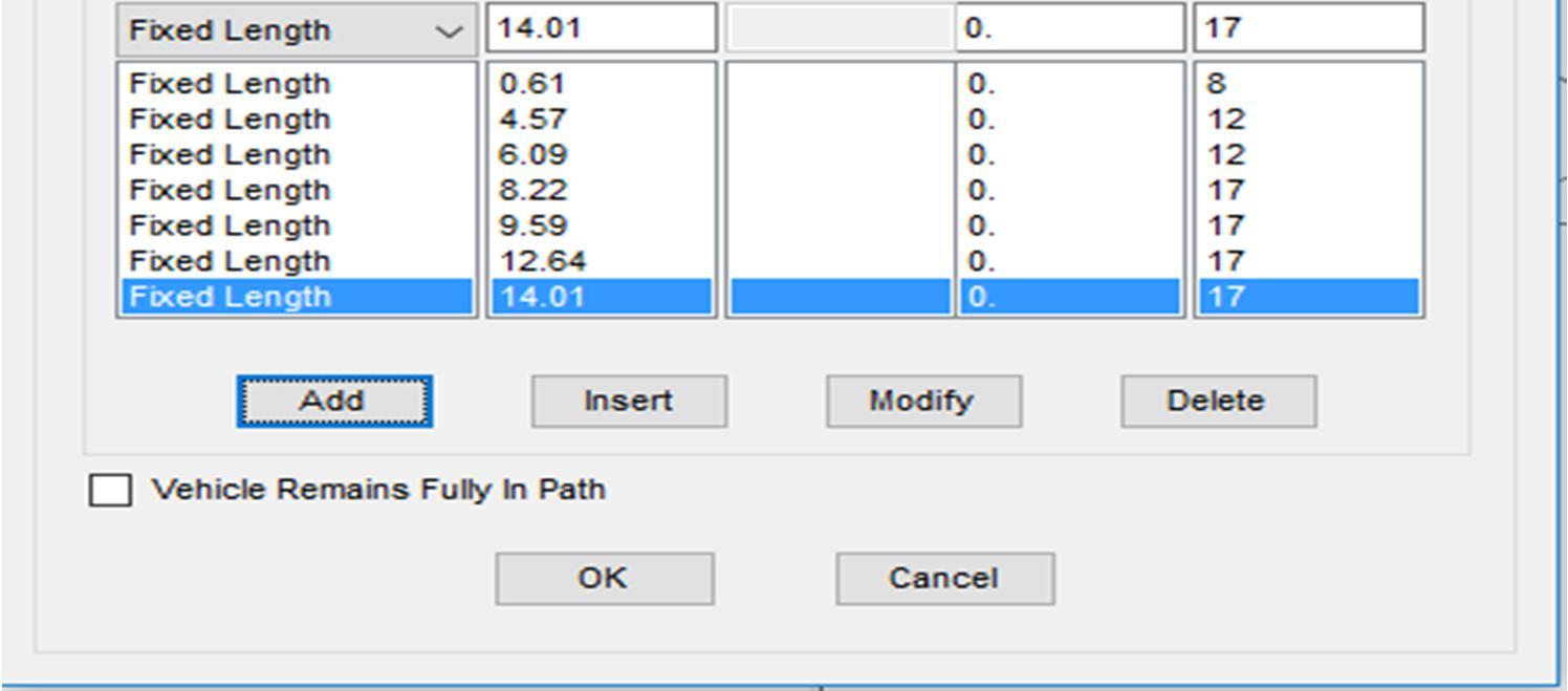
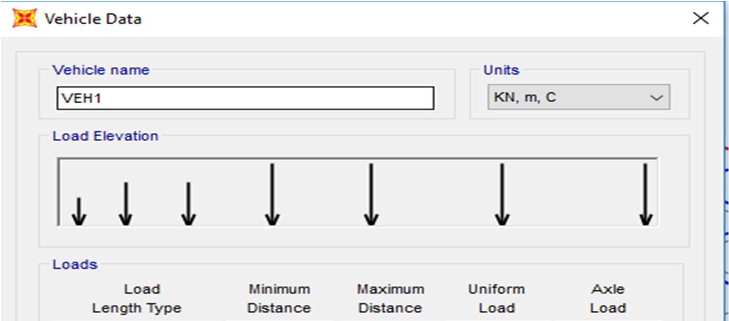
Allotting loads as IRC Class AA and seismic Provisions.
Arrangement of results and post processing outputs.

Following steps are considered for completion of this project are as follows:
Step1: Selection of the math of the superstructure by utilizing an organized framework in SAP 2000 or plot over the AUTO CAD, which can be imported in SAP 2000 according to the element of the support, c/c separation of joints, and no of interfacing membrane.

Step 2: Bridge models with same ranges were set up of similar measurement and same loading Conditions according to Indian Road Congress Class AA and seismic loading condition. Comparative analysis of two bridges are considered in the study with a length and width of 300 meters and 7.5 meter. Fixed support are placed at the bottom of both the cases and in case of Cable stayed bridge, the cable diameter was considered as 600mm, which incorporate check width material property of the structure according to Indian areas.
The two cases considered in the investigation are as per the following:
Girder Bridge with Span 300m.
4 Modelling of Cable


ISSN: 2321 9653; IC Value:

10 Issue IX Sep

7.538

www.ijraset.com


2321 9653;


www.ijraset.com


International Journal
in
Science & Engineering Technology (IJRASET)

ISSN: 2321 9653; IC Value: 45.98; SJ Impact Factor: 7.538 Volume 10 Issue IX Sep 2022 Available at www.ijraset.com
Graph 4: Support reaction

V. CONCLUSION
The comparative analysis of the two bridges considered in the study concluded that,
1) In this comparative analysis it is clearly stated that Cable Stayed bridge is more stable in resisting load.
2) In this study Hydraulic calculation is determined using topography sheet available as per Indian standard using dickens formulae.
3) It is concluded that in terms of Bending moment Cable Stayed bridge is comparatively 31% more economical and stable than girder bridge.
4) It is observed that unbalanced forces at deck (shear force) is resisting in cable stayed bridge whereas in girder bridge un stability is observed.
5) It is observed in this study that reaction at support in Cable stayed bridge is comparatively low as compared to Girder bridge which state that stresses are properly distributed in Cable stayed bridge Case.
REFERENCES
[1] Khawaja Ali, Hiroshi Katsuchi and Hitoshi Yamada, [Comparative Study on Structural Redundancy of Cable Stayed and Extradosed Bridges Through Safety Assessment of Their Stay Cables], Engineering 7 (2021) 111 123.
[2] Priyanka Rajput , Nikita Thora, Monika Pagare and Raj Joshi, [Comparative Study of Economical Design Aspect of cable stayed Bridge with concrete , Steel, and prestressed deck girder using sap software], International Journal of Advanced Science and Technology Vol. 29, No. 8s, (2020), pp. 4740 4753.
[3] PuneetGarg and Rajesh Chaturvedi, [Analysis of Cable Stayed Bridge for Different Structural Model], International Journal of Engineering Research & Technology (IJERT), ISSN: 2278 0181, Vol. 8 Issue 07, July 2019.
[4] KumudbandhuPoddar and Dr. T. Rahman, [Comparative Study of Cable Stayed, Suspension and Composite Bridge], International Journal of Innovative Research in Science, Engineering and Technology, Vol. 4, Issue 9, September 2015.
[5] HeemikaUpadhyay and Pradeep Pandey, [Comparative Study on Super Structure of Box Girder Bridge and Cable Stayedbridge with Extra Dosed Bridge], International Journal of Engineering Science Invention (IJESI), Volume 7 Issue 5 Ver. II || May 2018 || PP 21 26.

