
ISSN: 2321-9653; IC Value: 45.98; SJ Impact Factor: 7.538 Volume 10 Issue XII Dec 2022- Available at www.ijraset.com


ISSN: 2321-9653; IC Value: 45.98; SJ Impact Factor: 7.538 Volume 10 Issue XII Dec 2022- Available at www.ijraset.com

Ranjeet Singh1, Er. Gora Ram Sharma2 1, 2Bhai Maha Singh College of Engineering, Sri Muktsar Sahib
Abstract: The weld joints are used in various types of mechanical and civil engineering structures to strengthen the joints. The strength of T shaped weld joint significantly depends upon the design parameters of weld joint. The current research is intended to investigate the T shaped weld joint using techniques of Finite Element Analysis (FEA). The FEA analysis is conducted on T shaped weld joint using ANSYS simulation package. The optimization studies are conducted on T shaped weld joint to determine the effect weld joint parameters on induced deformation. From the optimization studies, the dimensions corresponding to weld height is determined for maximum and minimum deformation of T shaped weld joint.
Key Words: Weld Joints, Optimization, Weld Analysis
Welding is a process involving joining of dissimilar elements by heating at high temperatures. The welding process may or may not involve application of pressure. The type of filler material to be used depends upon type of welding. The welding process enables to make permanent joints in automobile components, railway wagons, machine components, machine components and other structural frames.
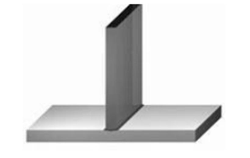

Tee joints are used when one part must be joined to the centre of another part forming a “T”. Like the other types of weld, there are several ways that this joint can be prepared and welded, each with their own benefits and disadvantages. Most methods of welding tee joints involve welding the two joints between the parts, with either a high or low energy density beam.
Wahab et. al.[1] have conducted experimental investigation on fillet weld joint to determine normal stress and shear stress under different misalignment conditions. The critical regions of fillet weld joints are determined from the research. Lee et. al.[2] have conducted numerical investigation of cantilever beam with welded joints. The analysis was conducted under tensile loading conditions as well as axial loading conditions. The lateral deformation, transverse stresses are determined for Ludwick cantilever beam material.
Wilcox et. al.[3] have presented analytical theory on stress evaluation of weld joints. Different theories are proposed and out of all the fillet weld theory is found to be more pragmatic and in close agreement with various types of numerical results. The effect of longitudinal loading and oversizing of weld joints on corner stress is also evaluated.
Mahapatra et al. [4] have conducted research on filleted weld joint using experimental techniques. The effect of angular distortion on weld stress, notch stresses are evaluated. Various factors which can mitigate the induced stresses on weld joint is presented.
ISSN: 2321-9653; IC Value: 45.98; SJ Impact Factor: 7.538 Volume 10 Issue XII Dec 2022- Available at www.ijraset.com

Kumose et al. [5] have conducted research on elastic straining of welded joint using both numerical and experimental techniques. The effect of pre-straining and post-straining on induced distortion of welded joints is presented. Different factors determining prestrain and post-strain of fillet welded joints are determined. The effect of flange thickness on weld stresses is also investigated. Michaleriset. al. [6] have conducted research on weldment using experimental techniques. The effect of thermal tensioning, preheating on weld stresses on distortion are investigated. Thermal tensioning works to “control residual stress and distortion by generating a tensile strain and the weld zone prior to and during welding by imposing a temperature differential” [6]
The current research is intended to investigate the T shaped weld joint using techniques of Finite Element Analysis (FEA). The FEA analysis is conducted on T shaped weld joint using ANSYS simulation package. The effect of weld height on lateral deformation of T shape weld joint is investigated using Taguchi optimization method.
The FEA analysis is conducted on T shaped weld joint involving different steps i.e. CAD modelling, meshing, boundary conditions and solution stage. The T shaped weld joint is developed in ANSYS design modeller using sketch and extrude tool. The T shaped weld joint is shown in figure 2.
Figure 2: CAD model of T shaped weld joint
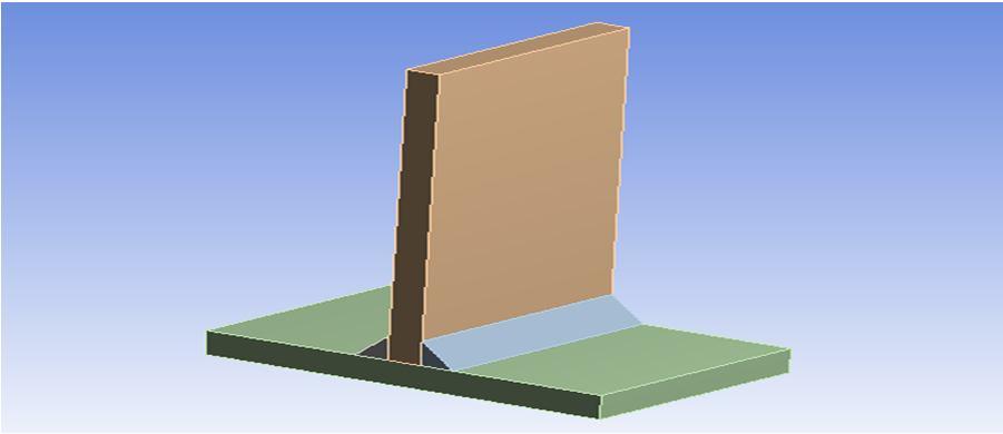
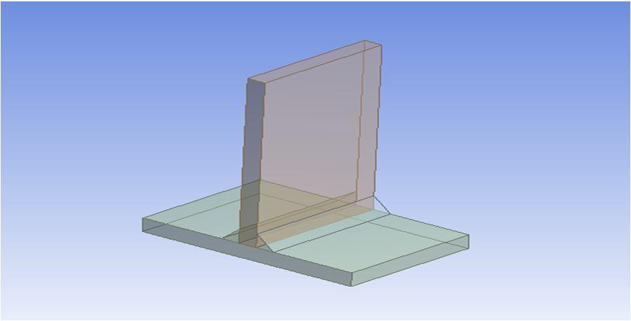

Figure 3: CAD model of T shaped weld joint
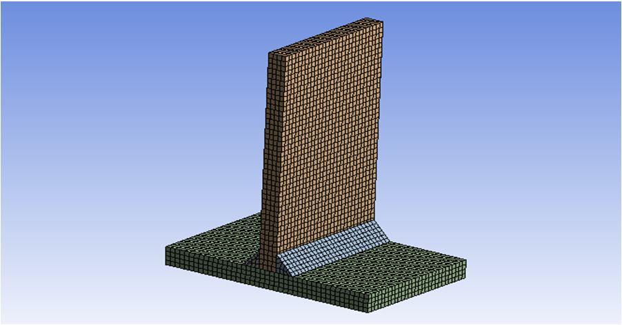
The developed CAD design of T shaped weld joint is imported in meshing module of ANSYS simulation package. The meshed model of T shaped weld joint is shown in figure 4. The meshing of T shaped weld joint is done using hexahedral/brick shaped element. The inflation and growth rate is set to 1.2.
Figure 4: Meshed model of T shaped weld joint From meshing, the number of elements generated is 10642 and number of nodes generated is 53343 as shown in figure 4.
ISSN: 2321-9653; IC Value: 45.98; SJ Impact Factor: 7.538 Volume 10 Issue XII Dec 2022- Available at www.ijraset.com


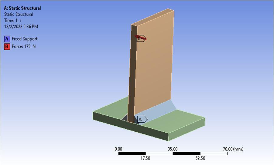
The structural boundary conditions are applied on the T shaped weld joint as shown in figure 5 above. The bottom of T shaped weld joint is applied with fixed support and vertical feature is applied with 175N load along transverse direction. After applying structural boundary conditions, the FEA simulation in run which involves individual matrix formulation and assemblage of global matrix formulation.
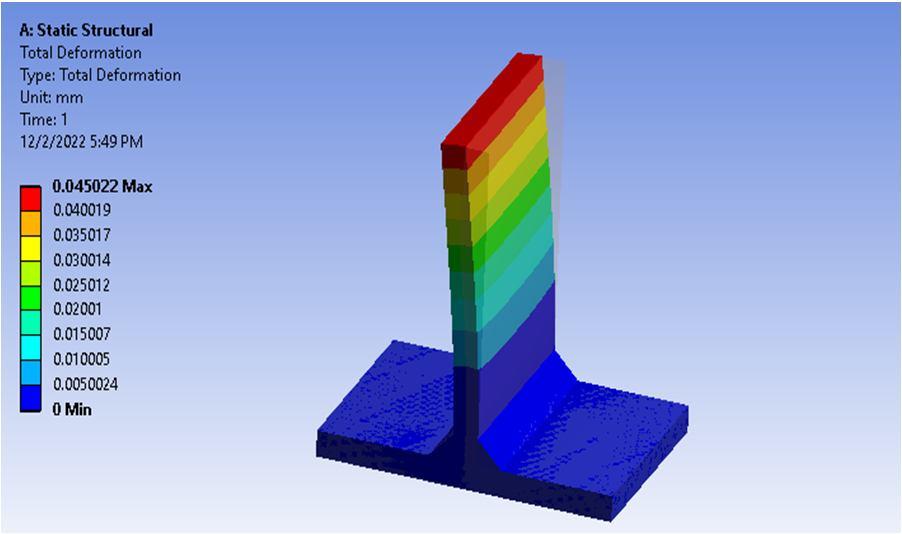
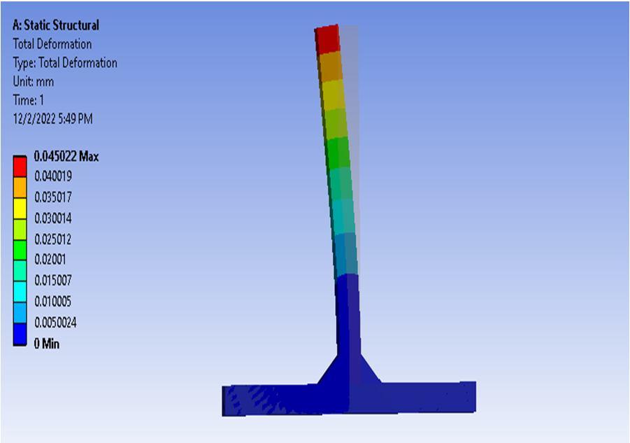
The structural analysis is conducted on T shaped weld joint to determine deformation and stresses. The maximum deformation is obtained on the vertical feature with magnitude of more than .04001mm as shown in figure 6.
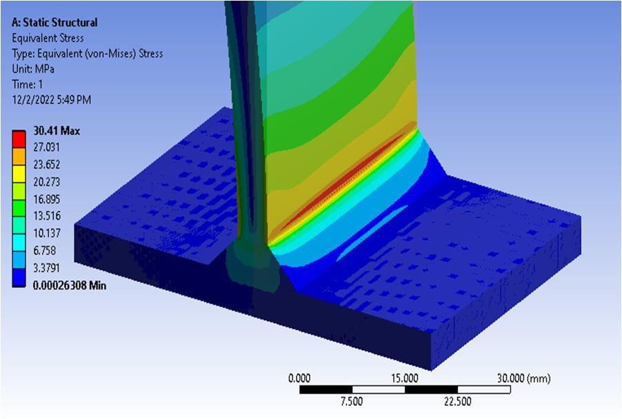
The equivalent stress is evaluated for T shaped weld joint as shown in figure 8. The equivalent stress is obtained to be maximum at the intersection zone of vertical and horizontal feature with magnitude of more than 27MPa.
ISSN: 2321-9653; IC Value: 45.98; SJ Impact Factor: 7.538 Volume 10 Issue XII Dec 2022- Available at www.ijraset.com

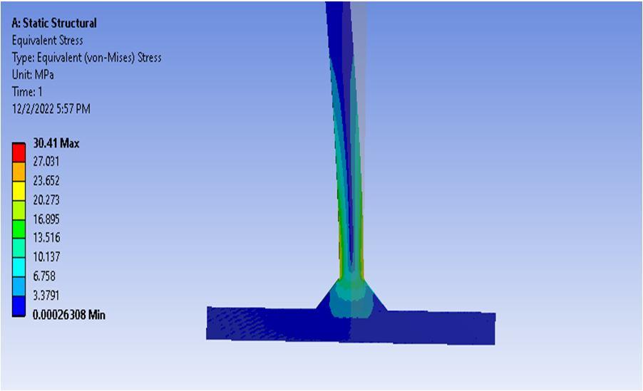
The equivalent stress obtained reduces along the vertical direction of T shaped joint and is minimum at the mid center region of vertical feature as shown in figure 9.

The higher stress at the intersection region signifies that this zone is likely to induce damage in the form of crack initiation which will then propagate to cause catastrophic damage to the weld joint.
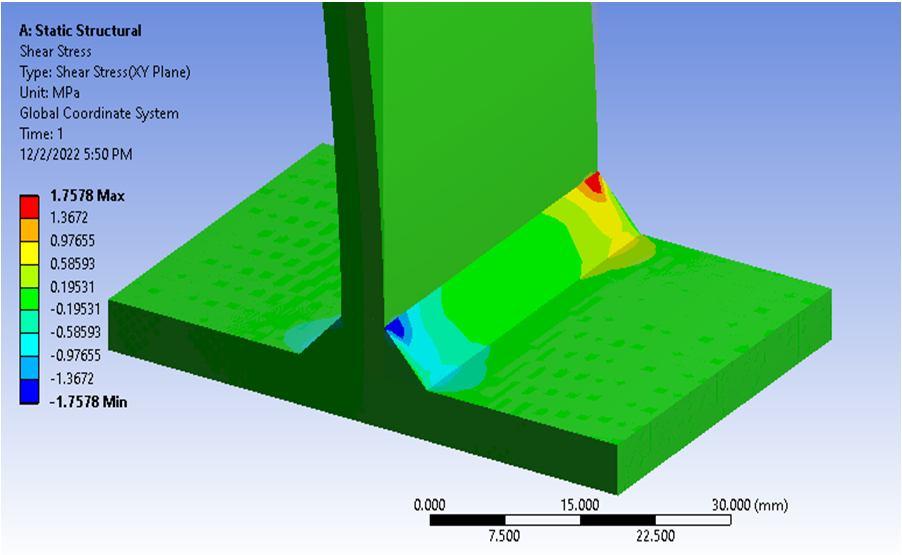
The shear stress distribution plot is generated for T shaped weld joint as shown in figure 10 above. The shear stress is higher at the corner regions with magnitude ranging from .97MPa to 1.36Mpa. The shear stress is almost uniform at the other regions of vertical and horizontal features of T shaped weld joint as shown in green coloured region.
ISSN: 2321-9653; IC Value: 45.98; SJ Impact Factor: 7.538 Volume 10 Issue XII Dec 2022- Available at www.ijraset.com


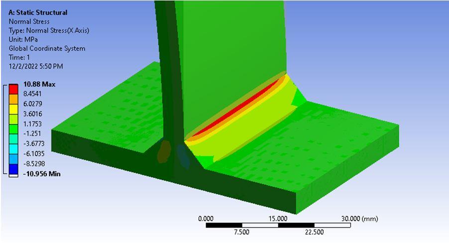
From the FEA analysis, the normal stress distribution plot is generated for T shaped weld joint which is similar to that of equivalent stress plot. The maximum normal stress is obtained is more than 6.02MPa.
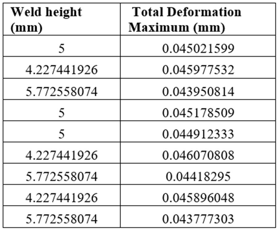
The effect of weld height on total deformation of T shaped weld joint is evaluated from the Taguchi optimization technique. The maximum total deformation is obtained for weld height of 4.22mm and minimum total deformation is obtained for 5.77mm weld height.
The use of ANSYS simulation package can significantly reduce the time required to evaluate the strength of T shaped weld joint subjected to transverse loading condition. The FEA simulation of T shaped weld joint is conducted to determine critical regions from where the crack can initiate and cause catastrophic damage to the structure. The optimization studies are conducted on T shaped weld joint to determine the effect weld joint parameters on induced deformation. From the optimization studies, the dimensions corresponding to weld height is determined for maximum and minimum deformation of T shaped weld joint.
[1] T. Ninh Nguyen and M. A. Wahab, “The effect of weld geometry and residual stresses on the fatigue of welded joint under combine
[2] Kyungwoo Lee, “ Large deflections of cantilever beams of nonlinear elastic material under a combined loading,” International Journal of Non-Linear Mechanics 37 (2002) 439–443.
[3] Robb C. Wilcox, “The effect of weld penetration on tensile strength of fillet welded joints”,B.S., Naval Architecture and Marine engineering, U.S. coast guard acadamy, 1991
[4] Mahapatra, M., G. L. Datta, B. Pradhan, and N. R. Mandal. “Modelling the effects of constraints and single axis welding process parameters on angular distortions in one-side fillet welds.” Proc. IMechE 221 Part B: 397-407.
[5] Kumose, T., T. Yoshida, T. Abbe, and H. Onoue. “Prediction of Angular Distortion Caused by One-Pass Fillet Welding.” Welding Journal. 1954: 945-956.
[6] Michaleris, P., J. Dantiz, and D. Tortorelli. "Minimization of welding residual stress and distortion in large structures." Welding Journal 11 (1999): 361-366s.
[7] Okerblom, N.O. "The Calculations of Deformations of Welded Metal Structures." 1958 (Her Majesty’s Stationery Office, London).
ISSN: 2321-9653; IC Value: 45.98; SJ Impact Factor: 7.538 Volume 10 Issue XII Dec 2022- Available at www.ijraset.com

[8] Teng, T., and C. Lin. “Effect of welding conditions on residual stresses due to butt welds.” International Journal of Pressure Vessels and Piping 75 (1998): 857864.

[9] Teng, T., C. Fung, P. Chang, and W. Yang. Analysis of Residual Stresses and Distortions in TJoint Fillet Welds. International Journal of Pressure Vessels and Piping 78 (2001): 523-538.
[10] Tekriwal, P., and J. Mazumder. "Transient and Residual Thermal Strain-Stress Analysis of GMAW."Journal of Engineering Materials and Technology 113 (1991): 336-343.
[11] T. Lassen, ph. Darcis, and N. Recho,(2005) Fatigue behavior of welded joints part 1–Statistical methods for fatigue life prediction supplement to the welding journal, Sponsored by the American Welding Society and the Welding Research Council,pp.183-187.
[12] Teppei Okawa, Hiroshi Shimanuki, Tetsuro Nose, Tamaki Suzuki,(2013) Fatigue life prediction of welded structures based on crack growth analysis, Nippon steel technical report no. 102, pp.51-53.
