https://doi.org/10.22214/ijraset.2023.49235

11 II
February 2023
ISSN: 2321-9653; IC Value: 45.98; SJ Impact Factor: 7.538
Volume 11 Issue II Feb 2023- Available at www.ijraset.com

https://doi.org/10.22214/ijraset.2023.49235
ISSN: 2321-9653; IC Value: 45.98; SJ Impact Factor: 7.538
Volume 11 Issue II Feb 2023- Available at www.ijraset.com
Kishor kumar Ukirde1, Swaraj Pawar2, Darshan Rahane3, Bhushan Sagar4, Tushar Shinde5
1Assistant Professor, 2, 3, 4, 5Undergraduate Student, Department of Aeronautical Engineering, Parul University, Vadodara, India

Abstract: This study aims to analyse the flow characteristics and drag profiles of six different fin geometries - clipped delta, swept, trapezoidal, elliptical, rectangular, and triangular - for subsonic, transonic, and supersonic flow at different Mach numbers. By comparing the aerodynamic characteristics of these fin variants, the research aims to identify the most efficient fin geometry for each Mach regime. This study will benefit missile designers in selecting the most suitable fin geometry for their mission by providing information on the efficiency of each fin geometry at different Mach numbers. The findings of this research will enable the development of more efficient and effective fins for missile models.
Keywords: Missile, Computational Fluid Dynamics, design methodology, subsonic flow, Supersonic flow, On-shape, Ansys.
Missiles are powerful weapons with a wide range of applications, including military, scientific, and exploration missions. The design of a missile is crucial to its effectiveness and success, with each component serving a specific purpose. Among the major sections of a missile, the nose cone, mid-section, and boat tail section work together to maximize efficiency and stability during flight. However, the fins of a missile play a critical role in providing stability and control during flight, making them essential components in missile design. The design and analysis of missile fins involve a complete insight of aerodynamics. Any errors in the design or analysis of the fins can lead to a potential loss of the mission, making it vital to conduct a thorough analysis of the fins to ensure their proper functioning and reliability. Additionally, drag performance on missile fins is a critical aspect of missile design and analysis, and the study of various fin design can improve missile performance and accuracy. This research paper will explore the design principles and aerodynamic properties of missiles, with a particular focus on the design and analysis of missile fins and their drag performance at different Mach regime.
The classification of guided missiles based on their target type, range, control system, and guidance, as well as their trajectory. Different guidance systems, including command guidance, homing guidance, and inertial navigation guidance, can be used in guided missiles. There are four types of missiles: ballistic missiles, cruise missiles, and glide missiles, and skip missiles. Ballistic missiles use a projectile to carry warheads and travel outside the earth's atmosphere for most of their range, while cruise missiles travel their entire range within the atmosphere at a constant altitude and speed. Glide missiles are launched at a steep angle, reach a certain altitude, and then glide towards the target, while skip missiles are launched at a high altitude with a thin atmosphere and skip along the atmosphere to reach their target.

A nose cone is an aerodynamic part missile and rockets that helps to ensure maximum efficiency and stability by modulating airflow behaviour and minimizing aerodynamic drag. The conically shaped forwardmost section of a missile comes in different types such as conic, spherical blunted conic, bi-conic, tangent ogive, elliptical, and parabolic. The chosen nose cone type for this study is the ogive nose cone because it has an arc that smoothly meets the body contour, creating no break in the line where the ogive smoothly connects to the cylindrical body. The centre of rotation of the arc is in the plane of the base of the nose. The ogival nose cone comes in two fundamental types: the tangent ogive nose cone and the second ogive nose cone. Most of the missile have configuration cylindrical in shape. This shape is advantageous in drag, easiness of manufacturing and the load carrying capability.
The tail section of a missile is the after part of the body that typically tapers towards the end and has fins for stabilization and steering during flight. The boat tail is a tapered portion of the after section that reduces drag by decreasing the base area of the body, and the number and shape of fins can vary based on the type and purpose of the missile
ISSN: 2321-9653; IC Value: 45.98; SJ Impact Factor: 7.538
Volume 11 Issue II Feb 2023- Available at www.ijraset.com
Fins are used on smaller rockets and missile to provide stability and control direction, which ensures safe and predictable flight. Different fin designs will produce different centre of pressure positions and streamlined, and rounded fins can almost double their performance and altitude capabilities. Advantages of fins include increased control effectiveness, high strength-to-weight ratio, ability to function effectively at high Mach numbers and angles of attack, and convenience for storage and transportation purposes.
The drag analysis is a crucial aspect in missile design, as it prevents them from decelerating and reaching their maximum altitude. The analysis includes nose drag, body tube drags, base drag, and fins drag. Nose drag comprises both pressure and skin friction drag, and ogive-shaped cones experience lower drag than other shapes. Body tube drag is limited to skin friction and drag is lowest at a zero angle of attack, depending on the length-to-diameter ratio. Base drag is caused by low pressure at the missile's rear due to flow separation and is influenced by the exhaust's exit pressure. Fin drags comprised skin friction and induced drag and depends on the fin shape, cross-sectional shape, and contributes to fin drag.
The paper by Neerumalla Sumanth (2022) investigates the aerodynamic characteristics of a missile with trapezoidal and planar fins using CFD analysis. The study reveals that the use of trapezoidal and planar fins decreases the drag acting on the missile, and as the angle of attack increases, there is an increase in the value of Cl and a decrease in the value of missile with planar fins. The study also provides valuable insights into the velocity and pressure contour for both planar and trapezoidal fins, showing the maximum velocity and pressure at the front part of the nose and the minimum velocity and pressure at the rear part of the missile. Overall, the study can be useful in optimizing missile design for better performance. [1]
The study by Pektaş and Ejder (2019) investigates the effects of different fin shapes on the apogee and stability of model rockets. The study found that span length and thickness are the dominant factors affecting the apogee of the system for all fin shapes, and that increasing span length leads to a decrease in apogee and higher aerodynamic drag. The study also suggests that the stability of the model rocket is primarily determined by the span length of the fins, and that an increase in weight accompanies an increase in span length and thickness. The results can be useful in the design and optimization of rocket fins for better performance and stability, and the use of response surface analysis demonstrates the applicability of this approach in studying the effects of various parameters on rocket performance.[2]
The study by Nizam BIN Dahalan and Iskandar Shah Ishak (2017) aimed to investigate the aerodynamic characteristics of a curved fin rocket. The study used a semi-empirical method and numerical solutions at various Mach numbers for subsonic and supersonic speeds and angle of attack. The study found that the normal force coefficient and drag coefficient increased as the angle of attack increased, and as the angle of attack increased, the velocity contour on the bottom of the rocket was slower than that on the top. The study provides insights into the aerodynamic characteristics of a curved fin rocket that can be useful in the design and optimization of rocket fins for improved rocket performance.[3]
The study by Nahel Sharma and Rakesh Kumar (2017) uses computational fluid dynamics (CFD) to investigate the aerodynamic behaviour of a single generic planar fin of a semi-circular missile model at subsonic to supersonic speeds. The authors found that the geometry of the fin plays an important role in missile aerodynamics, and that the trailing edge of the fin had little effect on the flow pattern around the fin. The study also found that the drag coefficient is dependent on the Mach number and that distinct oblique shock waves were observed after Mach 0.8. The insights from this study can be useful for the design and optimization of missile fins for improved performance.[4]
The study by Emran Gulay et al. (2011) investigates the rolling moment coefficient of missile models with wrap-around fins (WAF) using computational fluid dynamics (CFD) and experimental data. The study aims to understand the effect of WAF on missile performance in subsonic, transonic, and supersonic flows. The study found that the calculated rolling moment coefficient for the WAF model differed from the measured rolling moment coefficient by 14% in the supersonic region and 18% in the subsonic region. The study also highlights the importance of validating CFD results with experimental data and can be useful in the design and optimization of missile fins for improved performance.[5]
The study by James DeSpirito et al. (2002) investigated the aerodynamic coefficient and flow field of a generic canard-controlled missile configuration in supersonic flow using planar and grid fins. The authors used CFD simulations and found that grid fins produced lower side forces and reduced rolling moment compared to planar fins due to the uneven pressure distribution on the grid tail fins resulting from the interaction with the canard trailing vortices.
ISSN: 2321-9653; IC Value: 45.98; SJ Impact Factor: 7.538
Volume 11 Issue II Feb 2023- Available at www.ijraset.com
The study also highlighted the strong effect of canard deflection on the missile's forces and the ability of the canard's small surface area to reverse the rolling moment. The study provides valuable insights for the design and optimization of missile fins and can be useful in developing more efficient and effective missile fins for improved missile performance.[6]
The study by Kenneth J Moran and Philip J. Beran (1997) aimed to predict and understand the static stability characteristics of a generic missile configuration at high Mach numbers by simulating the flow around a complete Hypersonic Applied Research Technology missile for inviscid, laminar, and turbulent conditions at Mach numbers from 2 to 6. The study found that the pitching moment was dominated by compressibility effects, and the effectiveness decreased with increasing Mach numbers. The study provides insights into the static stability characteristics of a swept fin missile at high Mach numbers, which can be useful in the design and optimization of missile fins for improved missile performance in hypersonic flight.[7]
Munson et al. conducted a study in 1965 to investigate how the shape of missile fins impacted their aerodynamic characteristics, for both subsonic and supersonic missiles. They determined that a trapezoidal fin with a swept-back design was the most efficient shape for both types of missiles.[8]
In 1983, Watkins et al. studied the effect of missile fin size and shape on the missile's trajectory. The authors found that increasing the fin size and sweep angle improved the missile's stability and reduced drag.[9]
CFD analysis has been used in several studies to enhance missile fin design. In 2019, Mawhood et al. conducted a study using CFD simulations to improve the design of missile fins for a supersonic missile. The study discovered that the most efficient and stable fin design is a combination of anhedral angle and sweep angle.[10]
Overall, the literature suggests that missile fin design and analysis play a critical role in improving the overall performance of missiles.
A.
Figure1 depicts the designed Missile dimensions. In millimetres, the specified dimensions are given,

ISSN: 2321-9653; IC Value: 45.98; SJ Impact Factor: 7.538


Volume 11 Issue II Feb 2023- Available at www.ijraset.com

ISSN: 2321-9653; IC Value: 45.98; SJ Impact Factor: 7.538
Volume 11 Issue II Feb 2023- Available at www.ijraset.com
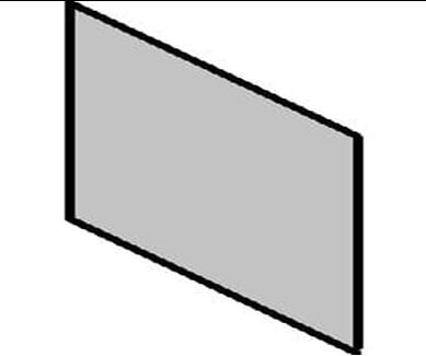
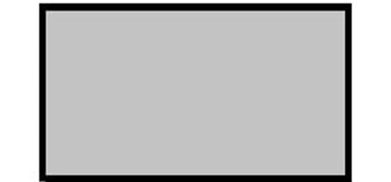
4) Rectangular fin description:

Fin planform
Fin configuration
Rectangular
Rectangular fin
Number of fins 4
Tip chord 240 mm
Root chord. Cr 240 mm
Fin thickness, t 2 mm
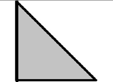
5) Triangular fin description:
Fin planform Triangular
Fin configuration
Triangular fin
Number of fins 4
Root chord. Cr 240 mm
Fin thickness, t 2 mm
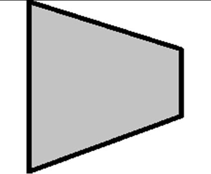
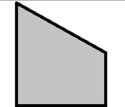
6) Swept fin description:
Fin planform Swept
Fin configuration Swept fin
Number of fins 4
Tip chord 120 mm
Root chord. Cr 120 mm
Fin thickness, t 2 mm
To meet specific requirements, each missile structure has a unique design. Due to the challenges of experimental testing, Computational Fluid Dynamics (CFD) is frequently utilized in the design process. In this study, a traditional CFD methodology was utilized to simplify the design process, which is depicted in Figure 3,
ISSN: 2321-9653; IC Value: 45.98; SJ Impact Factor: 7.538
Volume 11 Issue II Feb 2023- Available at www.ijraset.com
Using On-shape software, a 3D model of the missile was created based on dimensional specifications. The resulting model is displayed in Figure 4,


In the workbench, important steps were taken to assign the geometry, generate a mesh, and set up the simulation and results. The missile design was imported into the design modeller and enclosed with a cylindrical fluid domain, as shown in Figure 5,
This fluid domain was necessary for simulating air flow, and the inlet, wall, rocket, and outlet were assigned within the fluid domain. The inlet was the location where the air flow entered, and the outlet was the exit from the fluid domain. The wall acted as a control volume around the missile. The fluid domain had a Radius of 5 m and a length of 9 m.
ANSYS Meshing was used to create a high-quality mesh after the Missile geometry was established. The quality of the mesh, which must precisely replicate the physical phenomena in the flow domain, has an impact on the numerical solution's precision and consistency. It is essential to pay close attention to the inlet and outlet regions as well as the boundary layer at the body's top. Since calculating drag force is required for this problem, the boundary layer needs a fine mesh structure. Figure 6 displays the grid structure that was generated.
ISSN: 2321-9653; IC Value: 45.98; SJ Impact Factor: 7.538
Volume 11 Issue II Feb 2023- Available at www.ijraset.com
The denser mesh structure surrounding the missile profile is shown in Figure 6, with decreasing mesh density as one moves towards the boundary of the domain. Inflation layers were used to construct this structure, with a first layer thickness of 0.0015 mm The thickness of the first layer in the inflation layer was kept small to ensure it is located close to the missile body for proper resolution of the boundary layer.


Finally, a study was conducted to check the independence of results from the mesh structure. The comparison was made based on the calculated drag force and the findings are presented in Table below,
Reducing the mesh size by 50%, from 4.8 million to 1.26 million, did not result in a difference greater than 1.7%. Therefore, it is more practical to use 1.26 million elements instead of 4.8 million elements to save computational time and resources.
Following mesh generation, the simulation's boundary conditions were set up. For this study, the k-omega SST viscous model was selected, which is a two-equation eddy-viscosity model. This model uses the shear stress transport (SST) formulation to combine the best features of k-omega and k-epsilon models, resulting in a more accurate and stable solution. The k-omega formulation is used in the inner boundary layer, allowing the model to be directly usable down to the wall without additional damping functions. In freestream regions, the SST formulation switches to k-epsilon behaviour, avoiding responsive to inlet free-stream turbulence characteristics. While the SST k-omega model does produce larger turbulence levels in regions with normal strain, this is less pronounced than in the normal k-epsilon model. Overall, the SST k-omega model was used in the study due to its good behaviour in adverse pressure gradients and separating airflow.
The problem was set up using (ANSYS Fluent) and simulated using ANSYS Fluent Solver. The boundary conditions were defined using regions.
In ANSYS fluent-Pre, the inlet and outlet locations were designated as "Inlet" and "Outlet" boundary types, respectively. The inlet boundary was defined with a normal speed of 170 m/s to 850 m/s (0.5 Mach to 2.5 Mach), and the outlet boundary was defined with a static pressure of 0 Pa. The reference pressure is selected as 1 atm. The missile was defined as a non-slip wall, and the remaining regions were defined as symmetry. The fluid used was air, modelled as an ideal gas, and the k-omega SST turbulence model was employed. A residual target of 10^-6 was set, and a monitor point was used to check velocity convergence in the middle section. The problem was solved using steady-state conditions in ANSYS fluent Solver Manager. Results are presented in Section 5.
ISSN: 2321-9653; IC Value: 45.98; SJ Impact Factor: 7.538
Volume 11 Issue II Feb 2023- Available at www.ijraset.com
At Mach 0.5, the flow around the missile appears to be relatively smooth with no significant shock waves visible. This is because the missile is flying at a relatively low speed and the air particles can flow around the missile smoothly.


At Mach 1, the shock wave has just begun to form at the nose of the missile. This is because the missile is now flying at the speed of sound, and as the air particles approach the nose of the missile, they begin to compress and slow down, resulting in the formation of a shock wave (Normal).
At Mach 1.5, the shock wave has become more prominent and now extends farther back along the missile. This is because the missile is now flying at supersonic speeds, and the air particles are rapidly compressed and slowed down as they approach the nose, resulting in a strong shock wave.


ISSN: 2321-9653; IC Value: 45.98; SJ Impact Factor: 7.538
Volume 11 Issue II Feb 2023- Available at www.ijraset.com
At Mach 2, the shock wave has now fully formed and extends all the way back to the tail of the missile. This is because the missile is now flying at a higher supersonic speed, and the air particles are compressed even more rapidly as they approach the nose, resulting in a stronger and more extended shock wave.


At Mach 2.5, the shock wave appears to be like that at Mach 2, but with a more noticeable oblique shock wave forming ahead of the missile. This is because the missile is now flying at even higher supersonic speeds, and the air particles are compressed even more rapidly, resulting in the formation of an Oblique shock wave ahead of the missile, in addition to the strong shock wave along its body.


ISSN: 2321-9653; IC Value: 45.98; SJ Impact Factor: 7.538


Volume 11 Issue II Feb 2023- Available at www.ijraset.com
ISSN: 2321-9653; IC Value: 45.98; SJ Impact Factor: 7.538
Volume 11 Issue II Feb 2023- Available at www.ijraset.com
When a missile is at zero angle of attack, the airflow around it is symmetrical and a bow shock wave forms at its nose. The strength of this shock wave increases as the Mach number increases, along with the wave drag. At Mach numbers higher than one, oblique shock waves are formed at the leading edge of the fins, intersecting with the bow shock wave to create an area of increased pressure and drag behind the fins known as the shock wave interference region. This region is more pronounced at higher Mach numbers and is influenced by the shape and size of the fins.
At Mach 0.5, the airflow disturbance is minimal, and its effect on the missile is weak, but as the Mach number increases, the airflow compression becomes more intense, leading to increased drag.


At Mach 1, a strong bow shock wave is formed near the nose of the missile, increasing air pressure and temperature behind it.
At Mach 1.5 and above, the oblique shock waves merge to form a strong bow shock wave at the nose of the missile, resulting in a significant increase in drag due to the high-pressure region in front of the missile. Shock waves are formed due to the compressibility effects of the airflow, leading to deceleration and increased air pressure behind them.
0
We observe rectangular fin shapes have less drag at subsonic speed 0.5 Mach as compared to other fin shapes because they have a lower aspect ratio compared to other fin shapes, swept-back fins
ISSN: 2321-9653; IC Value: 45.98; SJ Impact Factor: 7.538

Volume 11 Issue II Feb 2023- Available at www.ijraset.com
A lower aspect ratio results in a shorter chord length and broader span, which reduces the size of the wingtip vortices that are generated at the tips of the fins. These vortices are a major contributor to drag at subsonic speeds, as they create turbulence in the airflow around the fins, which increases drag. Furthermore, rectangular fins are less prone to stall at lower angles of attack compared to other fin shapes, which also contributes to their lower drag. At low angles of attack, rectangular fins can produce lift with minimal drag, making them efficient for subsonic flight.
2) Transonic
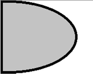
Figure 28 show the results For Trapezoidal and Elliptical fin Shape. The simulations were conducted at M = 0.5,1,1.5,2, And 2.5 and at angles of attack 00 .
In the transonic regime, elliptical Fin shape tend to have less drag compared to fins with another Fin shape. This is because the airflow around the fin can reach supersonic speeds near the tips of the fins, creating shockwaves and increasing drag. Fins with rounded shape help to minimize the formation of these shockwaves and reduce drag in the transonic regime
3) Supersonic
Figures 29 and 30 show the results For Clipped Delta, Tapered Swept and Rectangular fin Shape. The simulations were conducted at M = 0.5,1,1.5,2, And 2.5 and at angles of attack 00 .


ISSN: 2321-9653; IC Value: 45.98; SJ Impact Factor: 7.538
Volume 11 Issue II Feb 2023- Available at www.ijraset.com
We observe Clipped Delta and taper swept fin shapes have less drag at supersonic speed at 2.5 Mach, because they are designed to minimize the formation of shock waves, which are a significant source of drag at these speeds.
At supersonic speeds, shock waves are generated when the airflow over the surface of the fin is disrupted by the sudden increase in air pressure. These shock waves cause a significant increase in drag.
Delta and tapered swept fins are reduce the strength and number of these shock waves by gradually redirecting the airflow around the fin. The sharp leading edge of the Clipped delta fin and the tapering of the swept fin help to reduce the pressure gradient, minimizing the formation of shock waves and reducing drag.
In conclusion, the study of the flow characteristics around a missile (fins) at different Mach numbers has revealed the formation of shock waves due to the compressibility effects of the airflow. The intensity and size of these shock waves vary with the Mach number and the shape and size of the fins. The rectangular fin shape has been observed to have lower drag at subsonic speeds due to its lower aspect ratio and reduced wingtip vortices. The elliptical fin shape has been found to be more efficient in the transonic regime due to the minimization of shock wave formation. Finally, the Clipped Delta and taper swept fin shapes have been found to be effective in reducing shock wave formation and drag at supersonic speeds. The findings of this research are important in the design and development of missiles and other high-speed Rocket. Understanding the flow characteristics and the factors that influence drag can help in the development of more efficient and effective designs. Future research can explore further the impact of fin shape and size on the aerodynamic characteristics of missiles and other highspeed vehicles.
[1] Ukirde, Kishorkumar, and Shyam Rathod. "Aerodynamic Analysis of Various Nose Cone Geometries for Rocket Launch Vehicle at Different Mach Regimes." AIP Conference Proceedings. Vol. 2421. No. 1. AIP Publishing LLC, 2022
[2] Deepthi Mol S.S. "Numerical Study on Drag Reduction for Grid Fin Configurations." AIAA Modeling and Simulation Technologies Conference, January 2014. doi: 10.2514/6.2014-0519
[3] Aytaç Z. and Aktaş F., “Utilization of CFD for the aerodynamic analysis of a subsonic rocket”, Politeknik Dergisi, 23(3): 879-887, (2020). DOI: 10.2339/politeknik.711003
[4] Belega, B. A. (2015). Analysis of New Aerodynamic Design of the Nose Cone Section Using CFD and SPH. 3rd International Workshop on Numerical Modelling in Aerospace Sciences, NMAS 2015. DOI: 10.13111/2066-8201.2015.7.2.4
[5] Mawhood, P., Kontis, K., & Matejka, T. (2019). Optimizing supersonic missile fin design using computational fluid dynamics. Journal of Defense Modeling and Simulation: Applications, Methodology, Technology, 16(1), 89-102. doi: 10.1177/1548512918821566
[6] Watkins, W. S., Cook, T. W., & Uyehara, O. A. (1983). Wind tunnel and trajectory simulations of missile stability and control. Journal of Aircraft, 20(9), 766772. doi: 10.2514/3.45390
[7] Munson, J. E., & Miller, R. L. (1965). Fin shapes for subsonic and supersonic missiles. Journal of Aircraft, 2(2), 107-113. DOI: 10.2514/3.2768
[8] Moran, K. J., & Beran, P. J. (1997). Simulation of high Mach number missile configurations. In 12th AIAA Computational Fluid Dynamics Conference (p. 2715)
[9] DeSpirito, J., Kandil, O. A., & Shang, J. S. (2002). Aerodynamic analysis of a generic canard-controlled missile configuration. Journal of Spacecraft and Rockets, 39(6), 859-867. DOI: 10.2514/2.3885
[10] Gulay, E., Gocmen, T., & Yildiz, F. (2011). Experimental and numerical investigations of wrap-around fins for missile configurations. Journal of Aerospace Engineering, 24(4), 480-492. doi: 10.1061/(ASCE)AS.1943-5525.0000094
[11] Sharma, N., & Kumar, R. (2017). Aerodynamic behaviour of a single planar fin of semi-circular missile model at subsonic to supersonic speeds. Journal of Mechanical Science and Technology, 31(6), 2913-2922. doi: 10.1007/s12206-017-0543-4
[12] Nizam BIN Dahalan and Iskandar Shah Ishak. "Aerodynamic Characteristics of a Curved Fin Rocket." Journal of Advanced Research in Fluid Mechanics and Thermal Sciences 41, no. 1 (2017): 45-54
[13] Pektaş, M., & Ejder, E. (2019). Experimental investigation of the effects of different fin shapes on apogee and stability of model rockets. Aerospace Science and Technology, 91, 399-405. doi: 10.1016/j.ast.2019.05.026
[14] Sumanth, N. (2022). CFD analysis of missile with trapezoidal and planar fins. International Journal of Mechanical and Production Engineering Research and Development, 12(1), 1-10
[15] Chin, S. S. (2001). Missile configuration design. American Institute of Aeronautics and Astronautics