
10 XII December 2022 https://doi.org/10.22214/ijraset.2022.48233
1

ISSN: 2321-9653; IC Value: 45.98; SJ Impact Factor: 7.538 Volume 10 Issue XII Dec 2022- Available at www.ijraset.com

1
ISSN: 2321-9653; IC Value: 45.98; SJ Impact Factor: 7.538 Volume 10 Issue XII Dec 2022- Available at www.ijraset.com

Abstract: In this paper, particle swarm optimization (PSO) optimized PI controlled five level UPFC is proposed for a double circuit transmission line. To enhance UPFC performance, a different approach is considered here. It uses simplified power system models to derive the decoupled power controllers, but detailed modeling of the UPFC power converters improves their ride-through capability. This paper introduces decoupled linear UPFC power controllers to obtain the reference ac voltages and currents for the two back-to-back-connected three-phase five-level NPC converters that enforce active and reactive power control in the transmission line. This paper proposes three main contributions to increase the dc-link voltage steadiness of multilevel UPFCs under line faults: 1) decoupled active and reactive linear power controllers; 2) real-time PWM generation; and 3) balancing of dc capacitor voltages. The MATLAB/SIMULINK model for the proposed circuit with PSO-optimized PI controlled five level UPFC is shown here with the results.
Keywords: unified power-flow controller (UPFC), particle swarm optimization, power flow, power flow controller, and FACTS
With the rapid development of power systems, how to improve its operational flexibility, controllability and stability is becoming an urgent problem in today's society, the emergence of Flexible AC Transmission System (FACTS) provides a new way to do this, many of which devices have been put into used. They all play an important role in the power system, for example, TCSC,SVC, STATCOM. As the most representative member of the FACTS family, The Unified Power Flow Controller (UPFC) has more control variables, Compared with the other FACTS devices, it can change a variety of system parameters during operation, make the system running more flexible, Therefore, it becoming more and more valued. With Flexible AC Transmission Systems (FACTS), the AC transmission grid is supported by power electronics to provide control. These devices enhance the functionality of the AC power grid. [1], [2]
The most versatile of the FACTS devices, is the Unified Power Flow Controller (UPFC). With a UPFC it is possible to control the balance of the transmitted power between transmission lines, thereby optimizing the use of a transmission grid. A UPFC does this by injecting a controlled series voltage on a transmission line. In (1), active and reactive power P, Q transported by an ideal purely inductive transmission line are given, in the function of sending and receiving end voltages , , line impedance , and phase angle . This is a commonly used model for overhead transmission lines of short length, whose impedance is mainly inductive [3], [4], [5]. As a UPFC can control the sending end voltage , phase angle , and line impedance , it can adequately control active and reactive power flow on a transmission line. = sin , = cos #(1)
In [6], the issue of UPFC modeling within the context of optimal power flow solutions is addressed. The UPFC model has been presented to control active and reactive power flow at the buses of the sending or receiving end. The UPFC model suitable for optimal power flow solutions is presented for the first time in this study. In [7], a novel method to incorporate the power flow control needs of FACTS in analyzing the optimal active power flow problem is indicated. The linearized (DC) system model is applied. Three essential kinds of FACTS devices, namely TCSC, TCPS, and the UPFC, are concerned. The proposed method decomposes the solution of such modified optimum power flow (OPF) problem into the iteration of two problems.
ISSN: 2321-9653; IC Value: 45.98; SJ Impact Factor: 7.538 Volume 10 Issue XII Dec 2022- Available at www.ijraset.com
The first problem is a load flow control sub-problem and the second one is a normal OPF analysis. Further research work is needed for other OPF algorithms with an AC network model. A supplementary damping controller for a UPFC had been proposed in [8]. The gains of the UPFC supplementary damping controller are adjusted in real time, based on online measured real and reactive power flows in transmission lines. To decrease the time required for the online gain adaptation process, an artificial neural network is designed. Power flows over the transmission line are used as inputs to the adaptive controller. The proposed damping compensator has effectively damped the electromechanical mode with an oscillation frequency of around 0.78 Hz. In [9], it proposes ANFIS system to find the optimal setting UPFC during the static operation of the system. The objective is described in the difference of the desired parameter and the actual one. The analysis concerns the normal increase in the loading conditions. The method is simulated in many small network configurations. The approach 20 needs a continual update in the patterns. The UPFC is installed in the system to control the power flow in certain transmission lines.
To enhance UPFC performance, a different approach is considered here. It uses simplified power system models to derive the decoupled power controllers, but detailed modeling of the UPFC power converters improves their ride-through capability. This paper introduces decoupled linear UPFC power controllers to obtain the reference ac voltages and currents for the two back-to-backconnected three-phase five-level NPC converters that enforce active and reactive power in the transmission line. The NPC converters share common dc-link capacitor C (Fig. 1) and rely on real-time PWM generators to enforce the shunt converter ac input currents and series converter line-to-neutral voltages The dc-link voltage is regulated by the shunt converter, while shunt and series converters balance the dc voltages of the dc-link capacitors. Real-time PWM generation and the double balance of the four dc capacitor dc voltages have been shown to enhance the voltage ride-through capability. Simulation results are presented to show the active and reactive
To optimize the gains of the PI controller used in the control system, PSO optimization is adopted. Particle swarm optimization (PSO), first introduced by Kennedy and Eberhart, is one of the modern heuristic algorithms. It was developed through the simulation of a simplified social system and has been found to be robust in solving continuous nonlinear optimization problems [10]. The PSO technique can generate a high-quality solution within a shorter calculation time and stable convergence characteristics than other stochastic methods [11]. The effectiveness of the proposed methods is compared to controllers without real-time PWM generation and decoupled active and reactive power control.
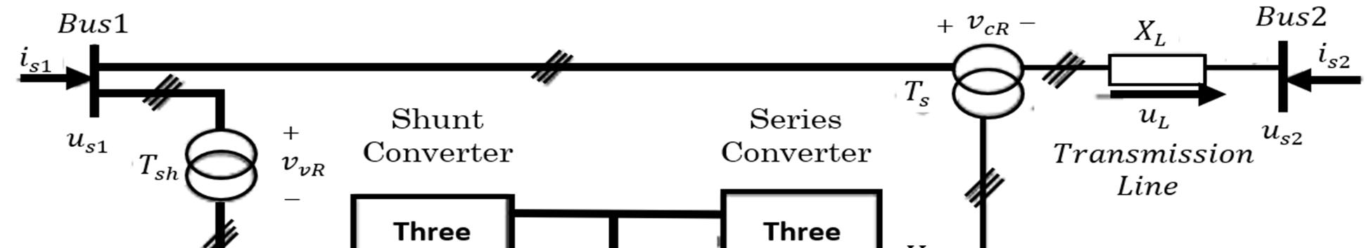
Fig. 1 shows the typical diagram configuration of the UPFC two high-power back-to-back NPC multilevel voltage-source inverters connected through a smoothing capacitor bank dc-link voltage. Oscillation damping control uses UPFC nonlinear control schemes. Unified power flow controller is a generalized synchronous voltage source, represented at the fundamental frequency by voltage phasor with controllable magnitude (0≤ ≤ ) and angle (0≤ ≤ 2 ), in series with the transmission line. The consists of two voltage-sourced inverters. These back-to-back inverters are operated from a common link provided by a storage capacitor. This arrangement functions as an ideal power inverter in which the real power can freely flow in either direction between the terminals of the two inverters, and each inverter can independently generate (or absorb) reactive power at its own output terminal.

ISSN: 2321-9653; IC Value: 45.98; SJ Impact Factor: 7.538 Volume 10 Issue XII Dec 2022- Available at www.ijraset.com
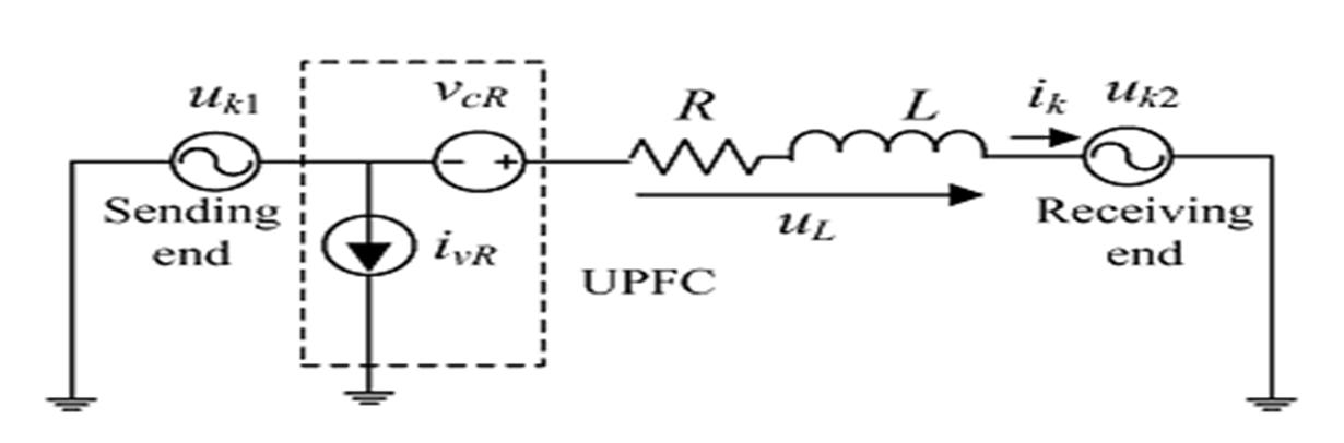
The series inverter provides the main function of the UPFC by injecting a voltage with controllable magnitude and phase angle α in series with the line via an insertion transformer. This injected voltage acts essentially as a synchronous voltage source. The transmission line current flows through this voltage source resulting in reactive and active power exchange between it and system. The inverter generates the reactive power exchanged at the ac terminal internally. The active power exchanged at the ac terminal is converted into dc power, which appears at the DC link as a positive or negative real power demand. The basic function of shunt inverter is to supply or absorb the real power demanded by series inverter at the common link to support the real power exchange resulting from series voltage injection. This link demand of series inverter is converted back to by shunt inverter and coupled to the transmission line bus via a shunt-connected transformer. In addition to this the shunt inverter can also generate or absorb controllable reactive power, if it is desired and thereby provides independent shunt reactive compensation for the line. The three main control parameters of are magnitude ( ), angle ( ) and shunt reactive current control of real and reactive power can be achieved by injecting series voltage with appropriate magnitude and angle. This injected voltage is transformed into reference frame, which is split into and . These coordinates can be used to control the power flow. The controllers for shunt and series branch are described below. Active and reactive PF can be controlled by injecting a Voltage with variable magnitude and phase angle through a step-up series coupling transformer Ts (Fig. 1), using the series converter line-to-neutral voltages, so that ,where is the series transformer voltage ratio. The shunt converter provides the UPFC-needed active power and usually controls the shunt reactive power. In steady state, the active power exchanged between the UPFC and the power system is close to zero, meaning constant dc-link voltage. The multilevel shunt converter input currents are controlled in the reference frame, so that the component keeps the dc voltage constant, while the component regulates the shunt reactive power. To obtain the UPFC decoupled active and reactive power controllers and assuming a balanced three-phase system, a simplified per-phase model of the transmission system as in Fig. 2 is considered, where line transversal and generator impedances were neglected when compared to the longitudinal impedance variations during line interruptions. Also, assuming controllers enforce fast dynamics, dc-link voltage disturbances can be neglected, together with power semiconductor switching dynamics. Therefore, the UPFC can be ideally represented as a controlled series voltage source and a controlled shunt current source. Using this equivalent circuit, the approximate dynamics of the three-phase currents in the transmission line are = + fork=1,2,3#(2)
Using Park transformation, the dynamics in the space are = + #(3) = + + #(4) = + + #(5)
Voltages and were obtained by applying Park’s transformation to the step-up converted voltages = N V ∝ and = N V
Fig.2. Equivalent circuit of a transmission system with UPFC
From (2), the frequency-domain model is ( ) ( ) = 1 ( + )2+( )2 ( + ) ( + ) ( ) ( ) #(6)
ISSN: 2321-9653; IC Value: 45.98; SJ Impact Factor: 7.538 Volume 10 Issue XII Dec 2022- Available at www.ijraset.com
Active and Reactive powers at line sending are P(s)= { } ( )+ ( )+ ( )#(7) Q(s)= ( ) ( ) ( )#(8)
Using (4) in (5) and making 0, active and reactive powers show constant terms, which depend on the generator voltages and line impedance, and controllable dynamic parts , determined by the series-injected voltages, according to (6)–(8) P( )= ( )+∆ ( )#(9) Q( )= ( )+∆ ( )#(10)
Where P (s), Q (s), and ∆P(s), ∆Q(s) are ( ) ( ) = ( + ) + + + × ( ) ( ) ( ) #(11) ∆ ( ) ∆ ( ) = ( + ) + + ( + ) × ( ) ( ) #(12)
To obtain fast controllers, this multiple-input multiple-output (MIMO) system can be decoupled by solving the model (8) for and to obtain the system-inverse dynamic model. It shows that control variables and are functions of the desired active and reactive powers ( ) ( ) = 1 + ( + ) ∆ ( ) ∆ ( ) #(13)
To derive linear decoupled and zero steady-state error closed loop controllers for and , consider a first-order decoupled dynamics with time constant.
From (10), ∆P(s), ∆Q(s) values are ∆ ( ) ∆ ( ) = 1 ∆ ( ) ∆ ( ) ∆ ( ) ∆ ( ) #(14) These values are used in the inverse dynamic model (9) to obtain. Thus, the control variables and are defined as ( ) ( ) = 1 ⎣ ⎢ ⎢ ⎢ ⎡ + ⎦ ⎥ ⎥ ⎥ ⎤ Δ ( ) Δ ( ) Δ ( ) ΔQ( ) #(15)
The decoupled power controllers include two fuzzy logic controllers to provide decoupled linear control of active and reactive powers, which allows independent control of the and injected powers in (10). Fig. 3 also includes coordinate transformation, realtime PWM generation, and connection to the UPFC system. The decoupled controller outputs are the reference values and for the series converter controller, with. These references are transformed to and applied to the series converter real-time PWM generation. This converter must also contribute to the dc-link capacitors’ voltage balance.
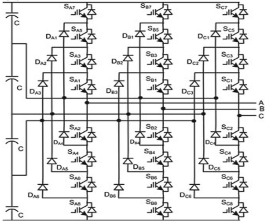
Fig.3. Three-phase five level NPC power converter
ISSN: 2321-9653; IC Value: 45.98; SJ Impact Factor: 7.538 Volume 10 Issue XII Dec 2022- Available at www.ijraset.com
The shunt converter regulates the shunt reactive power, but mainly controls the dc-link voltage = , supplying or absorbing the active power demanded by the series converter to keep constant the common dc-link voltage . Since the ac currents of the shunt inverter present fast dynamics compared to the slow dynamics of the dc-link voltage, the two shunt converter tasks must determine, respectively:
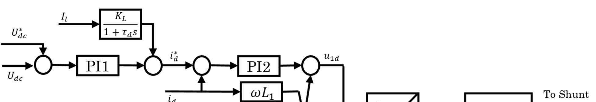
The ∗ shunt current is suitable to keep constant the dc bus voltage level, using PI controller The ∗ reference current suitable to keep constant the line voltage magnitude, using PI controller ∗ = ( ∗ )+ ( ∗ ) + 1+ #(16) ∗ = ( ∗ )+ ∫ ( ∗ ) #(17) = ( ∗ )+ ∫ ( ∗ ) + #(18) = ∗ + ∗ #(19)
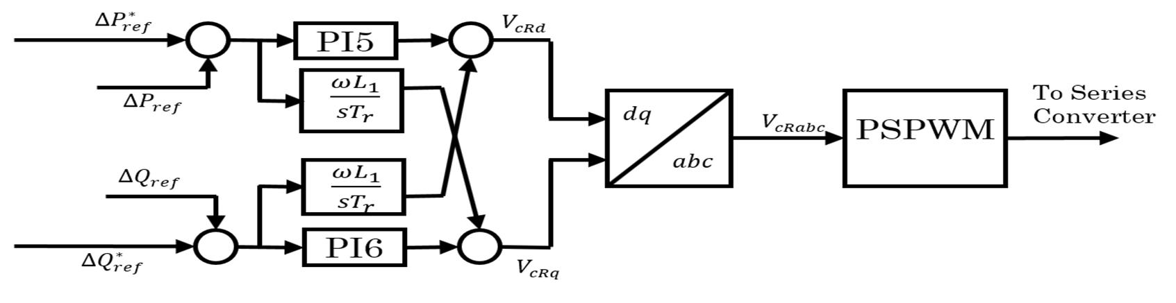
To control the active and reactive power in the transmission line, the series inverter must supply a series voltage with appropriate magnitude and angle. The inverter output voltages are nonlinear time variant functions of the dc-link capacitor voltages, which can be disturbed during line faults. To gain insensitivity to these disturbances, instead of a preprogrammed pulse width-modulator (PWM) generator relying on the dc-link voltage nominal value, the series inverter output voltage PWM is computed in real time so that the dc-link voltage variations are considered and do not impair the PF to be enforced by the series converter. Failure to produce the desired PFs could lead to transmission system shut down. PWM generation methods ensure that voltage pulses must have the same volt-second average of the fundamental sinusoidal (i.e., the time integral of the n-level voltage waveform minus the value of the sinusoidal should be zero). Therefore, to real time compute the PWM, a switching period is chosen, where the output voltages
, are used to generate pulses required by five level NPC inverter of series converter.
Fig.5. Series Converter PF controller block diagram
ISSN: 2321-9653; IC Value: 45.98; SJ Impact Factor: 7.538 Volume 10 Issue XII Dec 2022- Available at www.ijraset.com
of shunt converter and , , , of seroes converter are PI controller gains of the control system. These gains are optimized by using trial and error methods. The disadvantages of trial and error tuned PI controllers are that it gives rise to a higher maximum deviation, a longer response time and a longer period of oscillation than with other intelligent controllers. This type of control action is therefore used where the above can be tolerated and offset is undesirable. Hence Particle Swarm Optimization is adopted to optimize the PI controller gains of UPFC control system.
Particle Swarm Optimization (PSO) is a swarm intelligent algorithm, inspired from birds’ flocking or fish schooling for the solution of nonlinear, nonconvex or combinatorial optimization problems that arise in many science and engineering domains.
Many bird species are social and form flocks for various reasons. Flocks may be of different sizes, occur in different seasons and may even be composed of different species that can work well together in a group. More eyes and ears mean increased opportunities to find food and improved chances of detecting a predator in time. Flocks are always beneficial for survival of its members in many ways If for a group of birds, the food source is the same then some species of bird's form flock in a non-competing way. In this way, more birds take advantage of discoveries of other birds about the location of the food.
A flock of birds have number of advantages in protecting themselves from the predator: More ears and eyes mean more chances of spotting a predator or any other potential threat. A group of birds may be able to confuse or overwhelm a predator through mobbing or agile flights.
In case of a group, large availability of prays reduces the danger for any single bird.
When birds fly in flocks, they often arrange themselves in specific shapes or formations. Those formations take advantage of the changing wind patterns based on the number of birds in the flock and how each bird’s wings create different currents. This allows flying birds to use the surrounding air in the most energy efficient way. However, the development of PSO requires simulation of some advantages of birds’ flock, to understand an important property of swarm intelligence and therefore of PSO, it is worth mentioning some disadvantages of the birds’ flocking. When birds form flock they also create some risk for them.
More ears and more eyes means more wings and more mouths which result more noise and motion. In this situation, more predators can locate the flock causing a constant threat to the birds. A larger flock will also require a greater amount of food which causes more competition for food.
This may result in death of some weaker birds of the group. It is important to mention here that PSO does not simulate the disadvantages of the birds’ flocking behavior and therefore, during the search process killing of any individual is not allowed as in Genetic Algorithms where some weaker individuals die out. In PSO, all individuals remain alive and try to make themselves stronger throughout the search process.
The improvement in potential solutions in PSO is due to cooperation while in evolutionary algorithms it is due to competition. This concept makes swarm intelligence different from evolutionary algorithms. In short, in evolutionary algorithms a new population is evolved in every generation / iteration while in swarm intelligent algorithms in every generation / iteration individuals make themselves better. Identity of the individual does not change over the iterations.
For the development of PSO model, five fundamental principles which determine whether a group of agents is a swarm or not
a) Proximity Principle: The population should be able to carry out simple space and time computations.
b) Quality Principle: The population should be able to respond to quality factors in the environment.
c) Diverse Response Principle: The population should not commit its activity along excessively narrow channels.
d) Stability Principle: The population should not change its mode of behavior every time the environment changes.
e) Adaptability Principle: The population should be able to change its behavior mode when it is worth the computational price.
ISSN: 2321-9653; IC Value: 45.98; SJ Impact Factor: 7.538 Volume 10 Issue XII Dec 2022- Available at www.ijraset.com
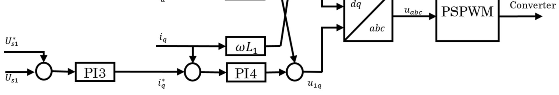
In PSO, the solution is obtained through a random search equipped with swarm intelligence. In other words, PSO is a swarm intelligent search algorithm. This search is done by a set of randomly generated potential solutions. This collection of potential solutions is known as swarm and each individual potential solution is known as a particle. In PSO, the search is influenced by two types of learning by the particles. Each particle learns from other particles, and it also learns from its own experience during the movement. Learning from others may be referred to as social learning while learning from own experience as cognitive learning. As a result, from social learning, the particle stores in its memory the best solution visited by any particle of the swarm which we call as gbest. As a result of cognitive learning, the particle stores in its memory the best solution visited so far by itself, called pbest
Fig. 6 Geometric Illustration of Particle’s Movement in PSO Process.
Change of the direction and the magnitude in any particle is decided by a factor called velocity. This is the rate of change in the position with respect to the time. With reference to the PSO, time is the iteration. In this way, for PSO, the velocity may be defined as the rate of change in the position with respect to the iteration. Since iteration counter increases by unity, the dimension of the velocity and the position becomes the same.
For a D-dimensional search space, the ℎ particle of the swarm at time step t is represented by a D-dimensional vector, = ( , ,…, ) . The velocity of this particle at time step is represented by another D-dimensional vector = ( , , , ) . The previously best visited position of the ℎ particle at time step t is denoted as = ( , , , ) . ‘ ’ is the index of the best particle in the swarm. The velocity of the ℎ particle is updated using the velocity update equation in (1).
= + ( )+ #(20)
The position is updated using the position update equation in (2).
= + #(21)
where = 1, 2,,,, represents the dimension and = 1, 2,..., represents the particle index. is the size of the swarm and and are constants, called cognitive and social scaling parameters, respectively or simply acceleration coefficients. , are random numbers in the range [0, 1]drawn from a uniform distribution. It appears from Eqs. (1) and (2) that every particle’s each dimension is updated independently from the others. The only link between the dimensions of the problem space is introduced via the objective function, i.e., through the locations of the best positions found so far gbest and pbest. Equations (1) and (2) define the basic version of PSO algorithm. An algorithmic approach of PSO procedure is given in Algorithm 1:
ISSN: 2321-9653; IC Value: 45.98; SJ Impact Factor: 7.538 Volume 10 Issue XII Dec 2022- Available at www.ijraset.com
Create and Initialize a D-dimensional swarm, S and corresponding velocity vectors; for = 1 to the maximum bound on the number of iterations do for =1 to S do for =1 to D do Apply the velocity update equation 1; Apply position update equation 2; end
Compute fitness of updated position; If needed, update historical information for pbest and gbest; end
Terminate if gbest meets problem requirements; end
The right-hand side in the velocity update Eq. (1), consists of three terms [3]:
1) The previous velocity v, which can be thought of as a momentum term and serves as a memory of the previous direction of movement. This term prevents the particle from drastically changing direction.
2) The second term is known as the cognitive or egoistic component. Due to this component, the current position of a is attracted towards its personal best position. In this way, throughout the search process, a particle remembers its best position and thus prohibits itself from wandering. Here, it should be noted that ( ) (superscript is dropped just for simplicity) is a vector whose direction is from to which results the attraction of current position towards the particle’s best position. This order of and must be maintained for attraction of current position towards the particle’s best position. If we write the second term using vector ( ) then the current position will repel from the particle’s best position.
3) The third term is called social component and is responsible for sharing information throughout the swarm. Because of this term a particle is attracted towards the best particle of the swarm, i.e., each particle learns from others in the swarm. Again, the same reason stands here also to keep the order of and in the vector .
It is clear that cognitive scaling parameter regulates the maximum step size in the direction of the personal best position of that particle while social scaling parameter regulates the maximum step size in the direction of global best particle. Figure 6 presents a typical geometric illustration of a particle’s movement in a 2- Dimensional space.
The convergence speed and the ability of finding optimal solution of any population-based algorithm is greatly influenced by the choice of its parameters. Usually, a general recommendation for the setting of parameters of these algorithms is not possible as it is highly dependent upon the problem parameters. However, theoretical and/or experimental studies have been carried out to recommend the generic range for parameter values. Likewise other population-based search algorithms, tuning of parameters for a generic version of PSO has always been a challenging task due to the presence of stochastic factors and in the search procedure. The basic version of PSO enjoys the luxury of very few parameters. One radical parameter is the swarm size which is often set empirically based on the number of decision variables in the problem and problem complexity. In general, 20–50 particles are recommended.
Other parameters are scaling factors, and . As mentioned earlier, these parameters decide the step size of the particle for the next iteration. In other words, and determine the speed of particles. In the basic version of PSO, = = 2 were chosen. With this choice, particle’s speed increases without control which is good for faster convergence rate but harmful for better exploitation of the search space. If we set = > 0 then particles will attract towards the average of pbest and gbest. > setting will be beneficial for multimodal problems while > will be beneficial for unimodal problems. Small values of and will provide smooth particle trajectories during the search procedure while larger values of and will be responsible for abrupt movements with more acceleration. Adaptive acceleration coefficients have also been proposed by the researchers.
ISSN: 2321-9653; IC Value: 45.98; SJ Impact Factor: 7.538 Volume 10 Issue XII Dec 2022- Available at www.ijraset.com
Stopping criterion is also a parameter not only for PSO but for any population based meta-heuristic algorithm. Popular stopping criteria are usually based on maximum number of function evaluations or iterations which are proportional to the time taken by the algorithm and acceptable error. A more efficient stopping criteria is based on the available search capacity of the algorithm. If an algorithm does not improve the solution with a significant amount up to a certain number of iterations, search should be stopped. In the control system of shunt converter and series converter there are six proportional gains and six integral constants ( ) The challenge is to determine all these constants for the to provide optimal active and reactive power control and voltage regulation. To do this for the power system in . 1 , the active and reactive power errors, voltage magnitude error, DC link voltage error and current errors are used as the measure of performance of the shunt and series controls. To arrive at the twelve optimal parameters using the particle swarm optimization, twenty particles are selected each providing a stable dynamic and transient control. The algorithm minimizes the following cost function. = (Δ ( )) + Δ ( ) + Δ ( ) + Δ ( ) + Δ ( ) + Δ ( ) #(22) Where Δ , Δ are active and reactive power errors, Δ is DC link voltage error, Δ voltage magnitude error and Δ and Δ are direct and quadrature axis current errors The cost is calculated and minimized to optimize PI controller gains of control system.
To validate the dynamic performance of the proposed NPC based five level PSO optimized UPFC control, the test network model of Fig. 1 with the shown parameters in table1 is used. Generators are modeled by three phase synchronous machines with exciters, driven by hydraulic turbine with governors, power stabilizers, and an output transformer. The selected test transmission network topology represents a system part with a 220-kV subsystem in parallel with another 220-KV subsystem.
Sending end Synchronous Machine 1000MVA, 13.8KV, 50Hz Transformer 1000MVA, 13.8KV/220KV
Receiving end Synchronous Machine 1200MVA, 13.8KV, 50Hz Transformer 1200MVA, 13.8KV/220KV
Line L1 Resistance 0.068 Ω/km Inductance 1.31 mH/km Capacitance 0.00885 µF/km Line Length 65km
Line L2 Resistance 0.068 Ω/km Inductance 1.31 mH/km Capacitance 0.00885 µF/km Line Length 65km
UPFC DC Link Voltage 56KV DC Link Capacitors each 750 µF Shunt Converter rating 100MVA Series Converter rating 100MVA
ISSN: 2321-9653; IC Value: 45.98; SJ Impact Factor: 7.538 Volume 10 Issue XII Dec 2022- Available at www.ijraset.com
(b)
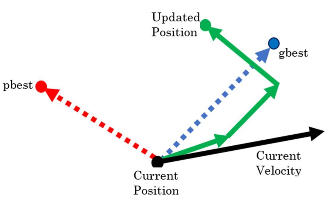
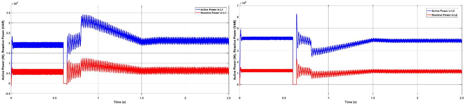
Fig.7. Step response of the UPFC controlled system with PI: (a) active and reactive power in the UPFC line L2 (b) active and reactive power in line L1, (a) (b)
ISSN: 2321-9653; IC Value: 45.98; SJ Impact Factor: 7.538 Volume 10 Issue XII Dec 2022- Available at www.ijraset.com
(c) (d) (e)
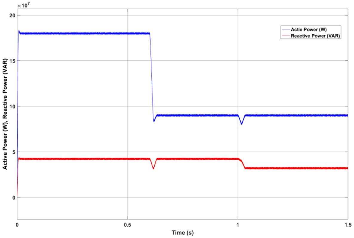
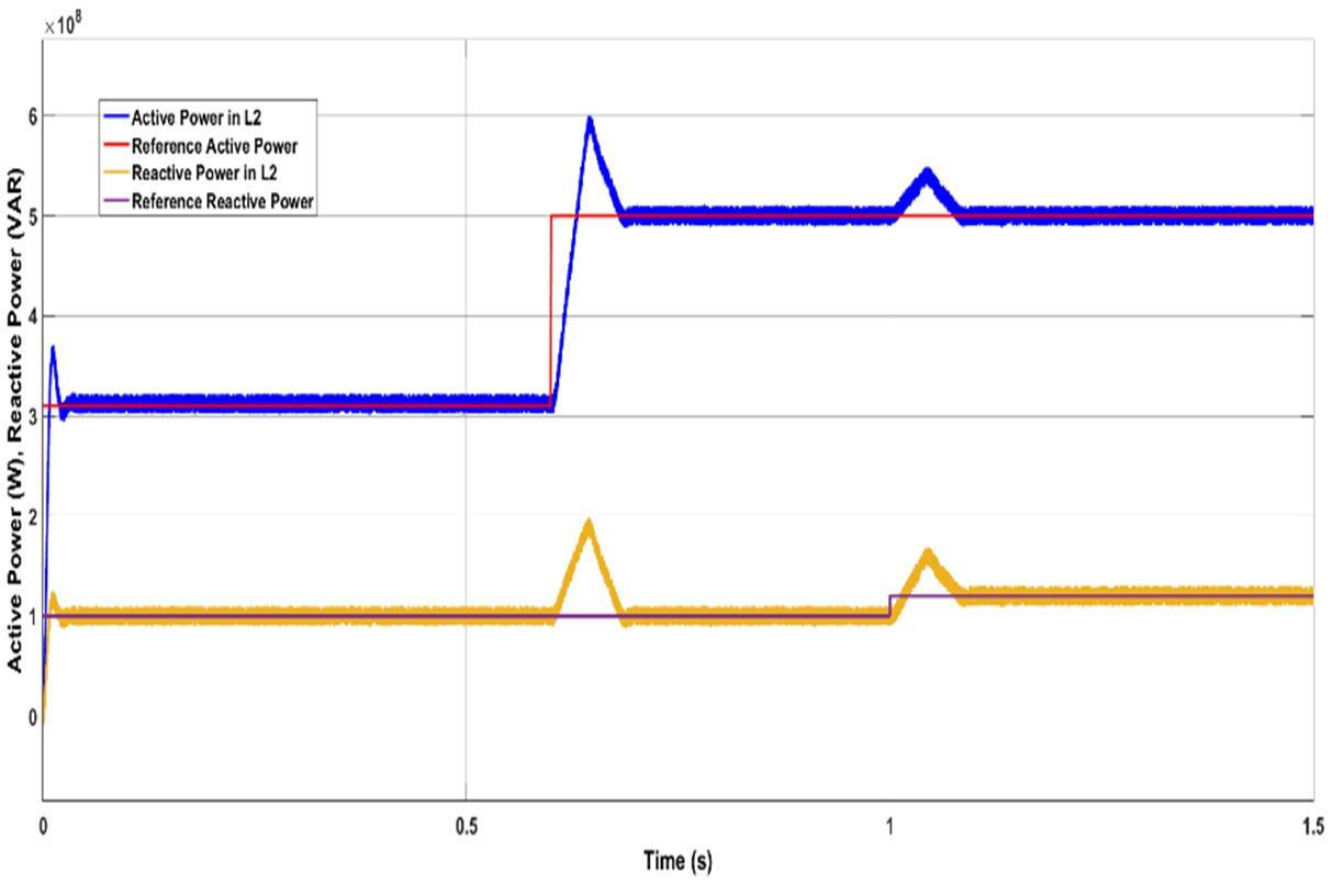
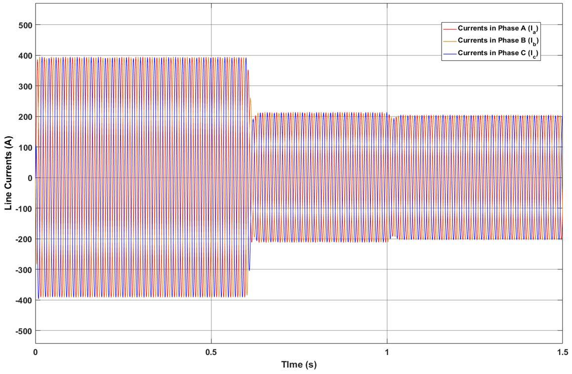
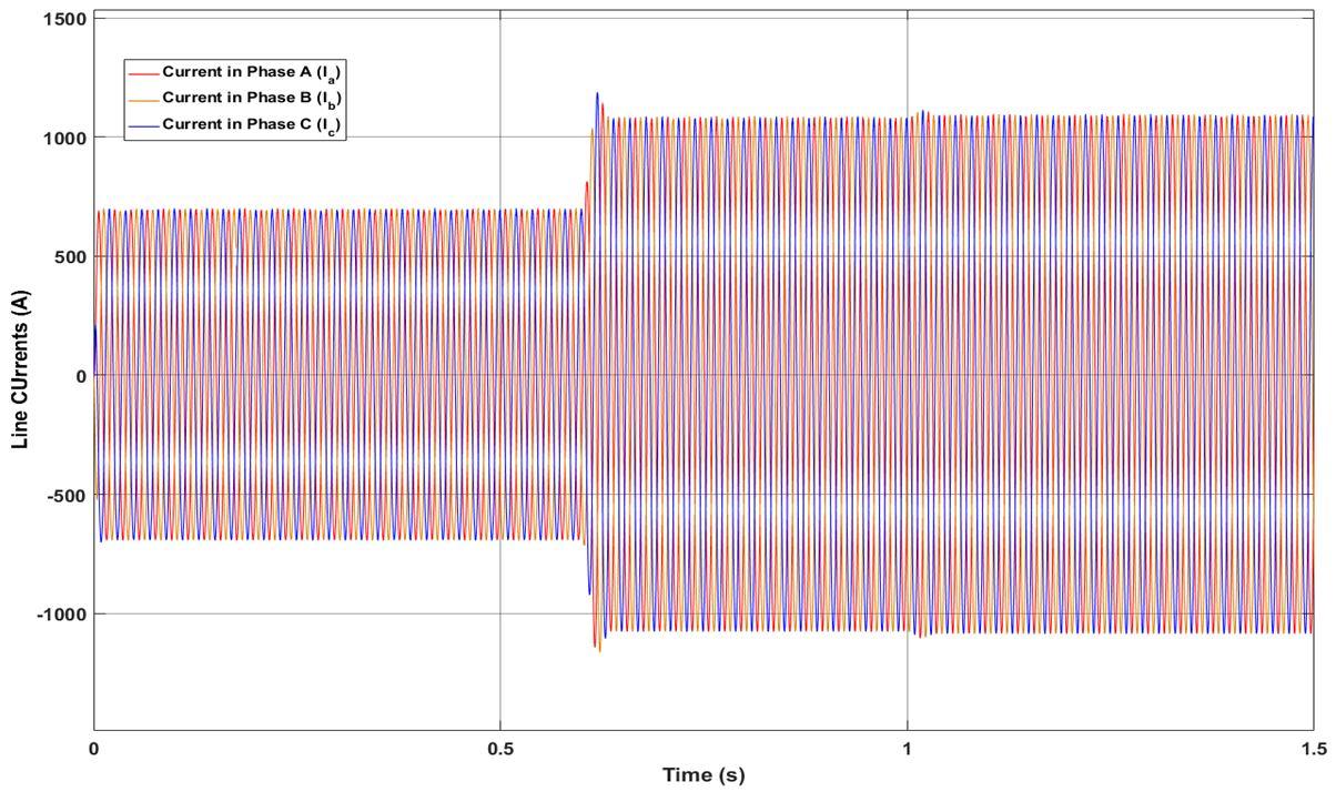
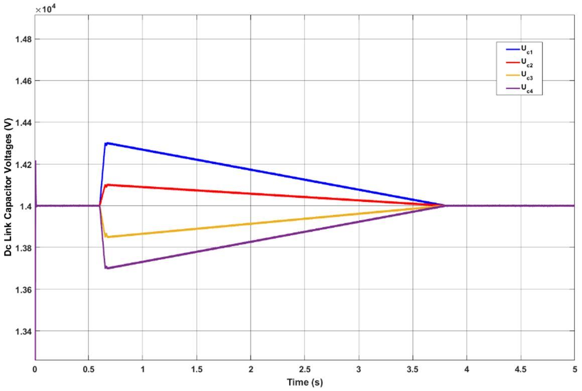
Fig.8. Step response of the UPFC controlled system with PSO tuned PI: (a) active and reactive power in the UPFC lineL , (b) active and reactive power in one of the L lines, and (c) dc-link capacitor voltages waveforms (d) Li line Currents (e) L2 Line Currents
ISSN: 2321-9653; IC Value: 45.98; SJ Impact Factor: 7.538 Volume 10 Issue XII Dec 2022- Available at www.ijraset.com
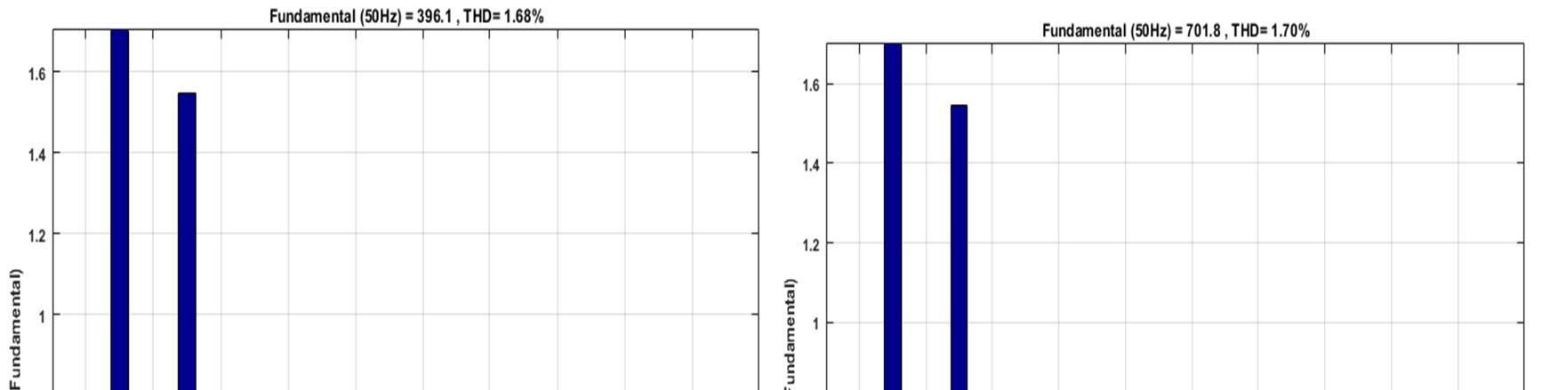
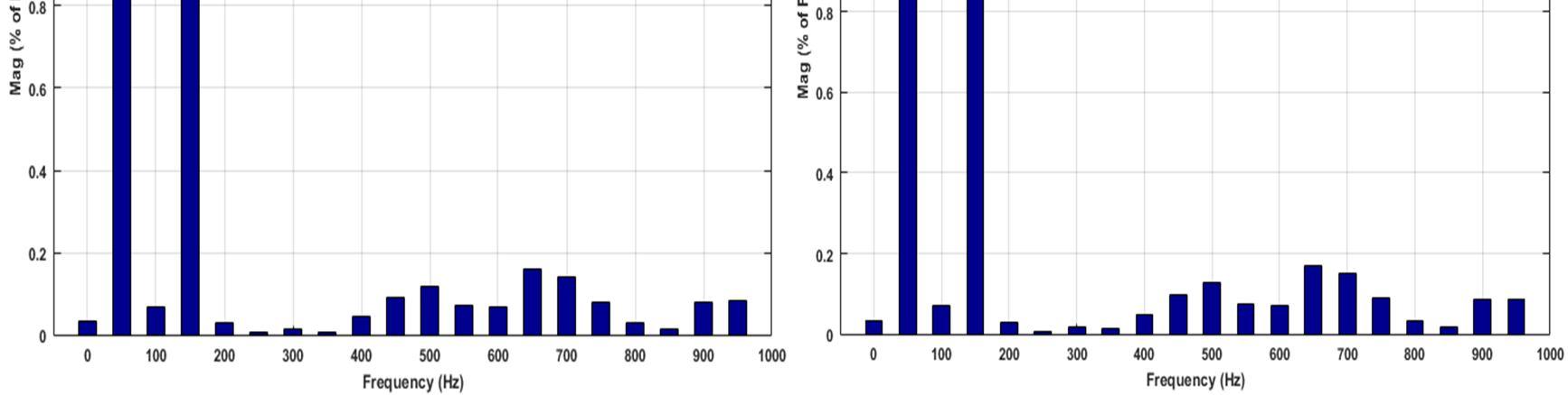
(a) (b) Fig.9. Total Harmonic Distortion of L1 and L2 line currents
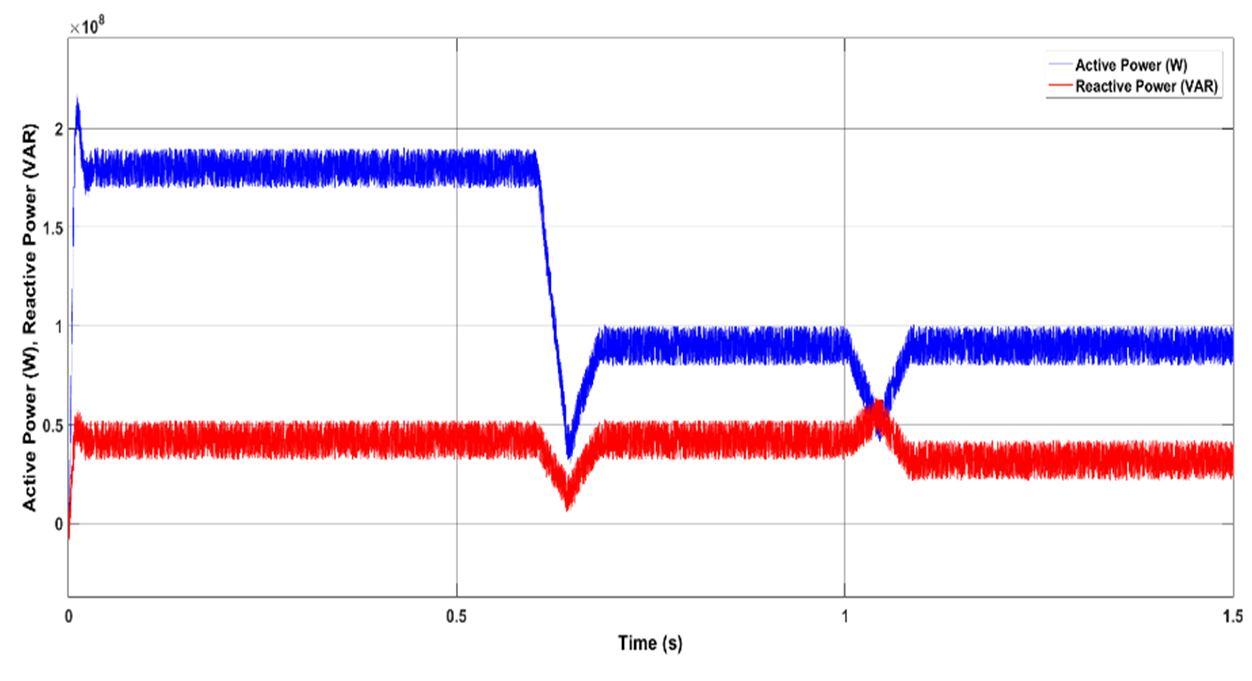
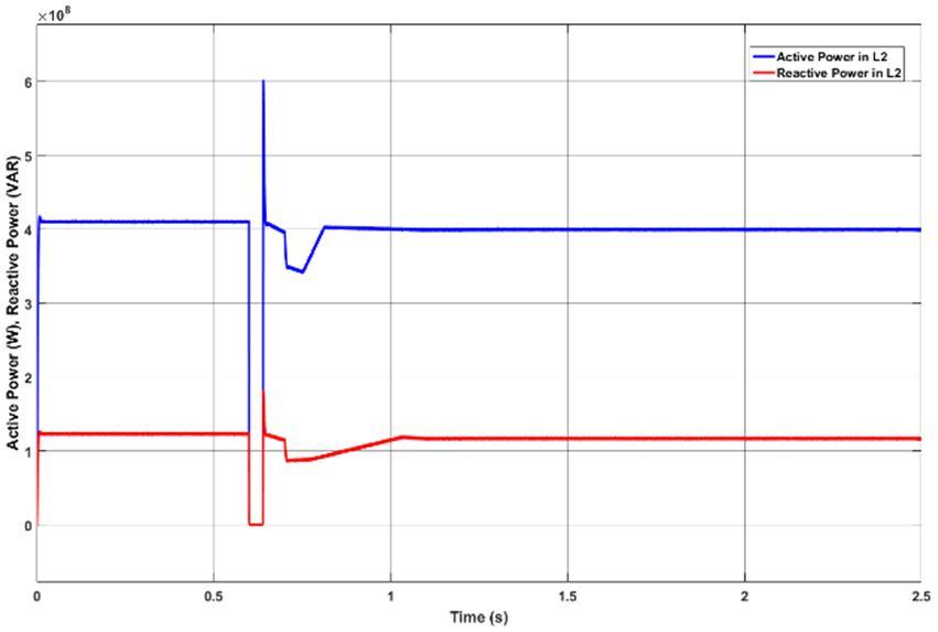
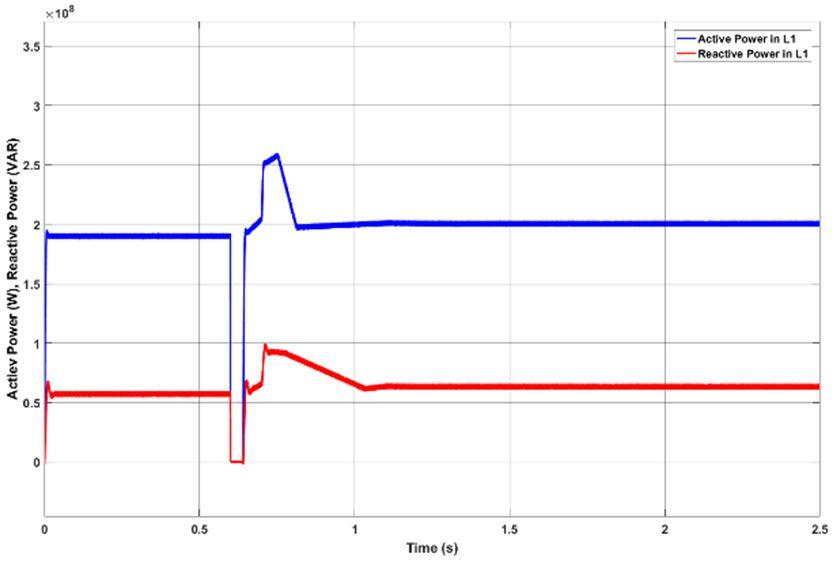
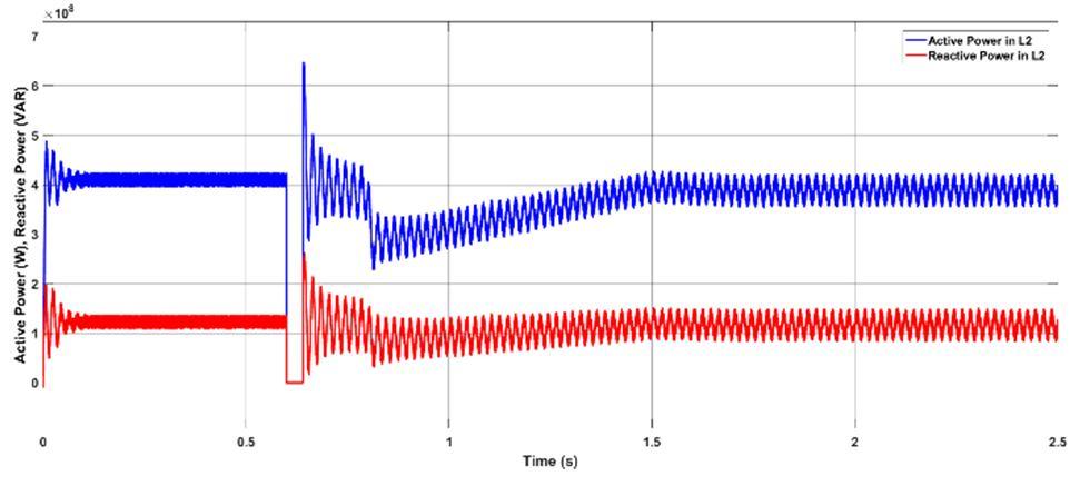
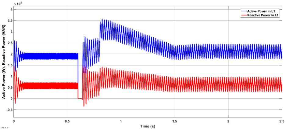
Good UPFC test results in this network are important on the transmission system and energy mix. The UPFC is placed between buses 2 and 4. To test the controllers, the converter models, including semiconductor switching, were built in the Matlab/Simulink environment within the network. In a first test, the system dynamic response to a step change in active and reactive power references for the second 220-kV line, controlled by the UPFC, was investigated. Initial values were P=312 MW and =90.00 MVAr. Steps are applied at t=0.6 s for =500.00 MW and at t=1 s for 120.00 MVAr. Initially UPFC is tested on double circuit transmission line with PI controller gains which are tuned by using trial and error method. These gains are tabulated in table 1. Active and reactive power flow in line L2 and L1 are depicted in fig 7(a) and (b) in which peak over shoot and stability time are 20% and 0.12 seconds respectively. Due to this poor performance of PI controller in UPFC in terms of peak overshoot and stability time, system can become unstable during dynamic conditions. To improve the tracking capacity of PI controllers, PSO is adopted to tune the gains. Gains which are optimized using PSO optimization are presented in table II. Active and reactive power flow in line L2 and L1 are depicted in fig 8(a) and (b) Voltages across DC link capacitors of five level multilevel inverter are presented in fig 8(c). line currents in line L1 and line L2 are presented in fig8(d) and fig8(e). fig 10 presents THD of line L1 and L2 currents. As seen in fig 8, active reactive power tracking by UPFC in Line L2 is improved due to PSO optimization in terms of peak overshoot and stability time. A three-phase fault is simulated in one of the 220-kV double lines ( 2) at 0.6 s, being cleared at 0.64 s, assuming a line outage. Fig 9, fig 10 and fig 11 depict the active and reactive power flow in L1 and L2 lines without UPFC, with normal PI controlled UPFC and with PSO optimized PI controlled UPFC. Fig. 9(a) and 10(b) shows the active and reactive power flows, without using the UPFC, in the healthy line L1 in parallel with the faulty line L2. During the three-phase fault, the transmitted power is nearly zero, but after the fault is cleared, line is overloaded. Using the multilevel UPFC, this line’s active and reactive PFs can be controlled in line ( 2). Fig 10(a) and 10(b) present the active and reactive power flows in line L1 and L2 with normal PI controller. Fig 11(a) and 11(b) present the active and reactive power flows in line L1 and L2 with PSO optimized PI controller. As can be seen from this figure, after the fault is cleared, the power transfer in this line will be controlled by the UPFC to maintain the active and reactive PF capacity limits of the line L1.
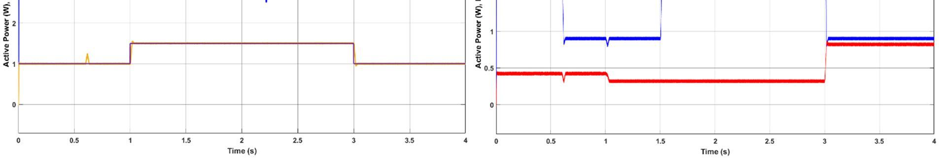
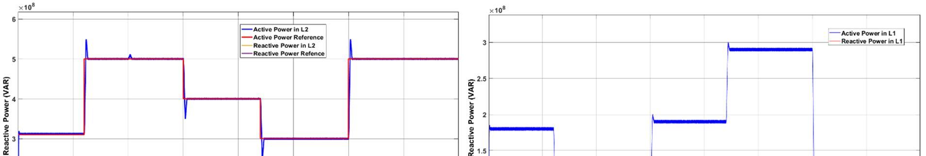
In fig 12 performance of PSO optimized PI controller is examined using dynamic conditions of active and reactive power change. Active power is change in the sequence of 310 MW, 500 MW, 400 MW, 300 MW and 500 MW at the timing sequence of 0, 0.6, 1.5, 2.2 and 3 seconds respectively. Reactive power is change in the sequence of 100 MW, 150 MW and 100 MW at the timing sequence of 0, 1 and 3 seconds respectively. As seen from fig 12 tracking capacity of proposed PSO optimized PI controller is efficient and also peak overshoot and stability time are reduced
ISSN: 2321-9653; IC Value: 45.98; SJ Impact Factor: 7.538 Volume 10 Issue XII Dec 2022- Available at www.ijraset.com
(a) (b)
Fig 9. Active and reactive power in L1 and L2 without UPFC
(a) (b)
Fig 10. Active and reactive power in L1 and L2 with PI controlled UPFC
(a) (b)
Fig 11. Active and reactive power in L1 and L2 with PSO tuned PI controlled UPFC
(a) (b)
Fig 12. Active and Reactive power in L1 and L2 line during reference change
ISSN: 2321-9653; IC Value: 45.98; SJ Impact Factor: 7.538 Volume 10 Issue XII Dec 2022- Available at www.ijraset.com
Table 2. PI Controller
Using Trial and Error method =0.1285, =0.6740, =1.0852, =0.9052, =2.3851, =1.1850, =6.7581, =10.0857, =3.8570, =2.0745, =3.6857, =5.0745
Using PSO optimization =0.0756, =0.2374, =0.9677, =1.1875, =3.0747, =0.9937, =5.0744, =12.7450, =2.9547, =1.9254, =4.4876, =3.2074
This paper proposes PSO optimization for tuning of PI controller of UPFC which controls active and reactive power flow in double circuit transmission line. Two five level NPC multilevel converters are adopted as shunt and series converters which are connected in back-to-back. The proposed UPFC control strategy includes: 1) decoupled active and reactive linear power control; 2) real-time PWM generation in both UPFC multilevel converters, dc-link voltage control gains with low sensitivity to dc link current, and 3) the balancing of the dc-link capacitor voltages using both multilevel converters. The dc-link capacitor voltages, which are usually balanced using only one of the multilevel converters, are balanced using both series and shunt multilevel converters, the results shows that the proposed technique with PSO gives better results. Optimization by PSO for PI controller gains improves tracking capacity of active and reactive power flow
[1] J. Steffy Amirtham & V. Uma M.E, “Optimal Location of Unified Power Flow Controller Enhancing System Security,” IEEE Second International Conference On Science Technology Engineering and Management (ICONSTEM) , 2016, pp. 326-331.
[2] Y. Zhang, G. Lu, W. A. Khan, Y. Zhang and Q. Zhu, "Direct Power Flow Controller A New Concept in Power Transmission," in IEEE Transactions on Power Electronics, vol. 35, no. 2, pp. 2067-2076, Feb.2020.
[3] Y. Zhang, S. Guan and Y. Zhang, "Single-Stage AC–AC Converter With Controllable Phase and Amplitude," in IEEE Transactions on Power Electronics, vol. 34, no. 7, pp. 6991-7000, July 2019, doi: 10.1109/TPEL.2018.2875093
[4] Ghadimi N, Afkousi-Paqaleh A and Emamhosseini A (2013) A PSObased fuzzy long-term multi-objective optimization approach for placement and parameter setting of UPFC. Arabian Journal for Science and Engineering 39(4): 2953–2963
[5] Shaheen H, Rashed G and Cheng S (2010) Application and comparison of computational intelligence techniques for optimal location and parameter setting of UPFC. Engineering Applications of Artificial Intelligence 23(2): 203–216.
[6] Hung GK, Chang CC and Chen CL (2003) Automatic phase-shift method for islanding detection of grid-connected photovoltaic inverters. IEEE Transactions on Energy Conversion 18(1): 169–173.
[7] Hunter L, Booth C, Finney S, et al. MVDC network balancing for increased penetration of low carbon technologies. Paper presented at: 8th IEEE PES Innovative Smart Grid Technologies Conference Europe (ISGT-Europe); October 2018; Sarajevo, Bosnia-Herzegovina https://doi.org/10.1109/ISGTEurope.2018.8571838
[8] . Chiandone M, Sulliogi G, Milano F, et al. Back-to-Back MVDC link for distribution system active connection. A network study. Paper presented at: 3rd International Conference on Renewable Energy Research and Applications (ICRERA); January 2015; Milwaukee, WI. https://doi.org/10.1109/ICRERA.2014.7016536
[9] H. E. Tooraji and N. Abdolamir, “Improving Power Quality Parameters in AC Transmission Systems Using Unified Power Flow Controller,” Research Journal of Recent Sciences, Vol.2, No.4, pp.84-90, Apr. 2013.
[10] N. G. Higorani and L. Gyugyi, Understanding FACTS: Concepts and Technology of Flexible AC Transmission Systems, WileyIEEE Press, 2019.
[11] ] J. Liu, Z. Xu, W. Fei, et al., “Comprehensive power flow analyses and novel feedforward coordination control strategy for MMCbased UPFC,” Energies, vol. 12, no. 5, 2019
ISSN: 2321-9653; IC Value: 45.98; SJ Impact Factor: 7.538 Volume 10 Issue XII Dec 2022- Available at www.ijraset.com
R. Jayachandra has obtained his M.Tech degree from JNTU Hyderabad. He has more than 10 years of teaching experience. He published 4 research papers at National and Internation level. He is presently a research scholar at JNTUH, Hyderabad, Telangana. He is working in the area of Facts controller & algorithms.

Email: saimedha.J@gmail.com
Prof.G.TULASI RAM DAS is presently with the Dept. of Electrical an Electronics Engineering, JNTUH, Hyderabad, Telangana, India. Prof Das also worked as Vice-Chancellor for the prestigious JNT University, Kakinada, Andhra Pradesh, India. Prof. Das obtained his B.Tech (EEE) from JNTU Hyderabad, M.Tech (Industrial Drives and Controls) from Osmania University, and PhD from IIT Madras. His research interests include Power Electronics, Power SemiConductor Controlled Electric Drives (IM, PMSM, BLDCM & SRM), Resonant Converters, Multilevel converters, Flexible AC Transmission Systems (FACTS), Power Quality, Wind Energy Conversion, and Solar PV cell technologies. Email: das123tulasiram@gmail.com