
10 IX September 2022 https://doi.org/10.22214/ijraset.2022.46685


Abstract: A vapor compression refrigeration system is a system that uses liquid refrigerant in a closed system which circulates the refrigerant through four stages in which it is alternately compressed and expanded, changing it from liquid to vapor. As this change happens, heat is either absorbed or expelled by the system, resulting in a change in temperature of the surrounding air that is passing over the unit's components. Nearly all of the refrigeration systems we use today use this cycle to accomplish cooling. VCRS system is made up of four main components: the evaporator, condenser, compressor and expansion valve. The evaporator and condenser are both a series of coils that are designed to create more surface area for the refrigerant to react with. Meanwhile, the compressor and expansion valve are mechanical units that control the amount of pressure and temperature change that occurs between the two stages. It was named after Jean Charles Athanase Peltier, the physicist who discovered the effect in 1834. Peltier discovered that when current is made to flow through a circuit consisting of two different types of conductors, a heating or cooling effect is observed at the junctions between the two materials. This change in temperature at the junction is called the Peltier effect. When electric current is passed through a circuit consisting of two different conductors, a cooling effect is observed in one junction whereas another junction experiences a rise in temperature. This change in temperatures at the junctions is called the Peltier effect. The effect is found to be even stronger when two different semiconductors are used in place of conductors in the circuit.
In this journal Two methods of refrigeration work together to get a good coefficient of performance (COP). The both vapour compression refrigeration method which good in control the inside temperature and peltier effect by combined together in a single setup. The heat generated from the two dissimilar semiconductors are used to change the complete phase transformation of the refrigerant system before entering into the compressor. The combined system we call it as hybrid experimental system. The COP of thermoelectric system in combined with VCRS is increased by proper heat dissipation, from hot side of the peltier units and these heat fluxes utilized by VCRS for its own benefit.
A domestic refrigerator consists of thermally insulated cabinet in which temperature remains below the ambient temperature. Domestic refrigerators work on Vapour compression refrigeration system, as it has good COP. Inaccurate temperature control inside the cabinet because of the stop start cycle of compressor is the major problem in VCRS. This has been affecting the proper preservation of foods. The liquid refrigerants pass through the expansion valve where their pressure reduces. This leads to mixture of liquid and vapour at lower temperature and pressure. The cold liquid vapour mixture then travels through the evaporator coil or tubes and is completely vaporized by cooling the warm air from the space refrigerated. This resulting refrigerant vapour returns to the compressor inlet to complete the cycle. When the suction vapour is drawn into compressor; there is possibility of wet vapour entering the compressor which consists of the vapourised droplet of the liquid. If appreciable amount of Un vapourised liquid is allowed to enter the compressor from the suction line, it may cause mechanical damage to the compressor. Superheating the suction vapour in little amount may eliminate the possibility of wet vapour entering the compressor. The objective of this work is to combine the two refrigeration methods, vapour compression refrigeration and thermoelectric refrigeration, in a single setup to use the heat fluxes generated from the hot side of the pettier plate for phase transformation of the refrigerant inside the evaporator coils and thus prevent the wet vapour entering the compressor. This also helps to get extra cabinet in hybrid system which is cooled by means of thermoelectric plate without inside temperature fluctuation. Experimental setups consist of three compartments freezer compartment, thermoelectric compartment and cooler compartment. Thermoelectric compartment is fitted just below the freezer compartment where it has the peltier plates arranged in such a way that the hot side of the Peltier plate comes in contact with the evaporator coiling of vapour compression system. The heat fluxes generated from the Peltier plate are absorbed by the evaporator coiling which carry to the compressor

T. Vamsi
Sk. Nayab Rasool
, V. Ratna Ramesh
, K. Hemanth
J.V.S.S. Neeraj
Venkateswara
International Journal
in Applied Science & Engineering Technology (IJRASET)
ISSN: 2321 9653; IC Value: 45.98; SJ Impact Factor: 7.538 Volume 10 Issue IX Sep 2022 Available at www.ijraset.com
There are different types of processes are available for vapour compression refrigeration systems. We studied some of those papers and those papers them are mentioned as follows:
1) Gareth F. Davies et al presents a survey of the “COOLING MICROPROCESSORS USING VAPOR COMPRESSION REFRIGERATION” cooling the microprocessor. Maintaining future high performance microprocessor chips within an acceptable operating temperature range (e.g., less than 85ºC), is likely to involve the removal of large quantities of heat (e.g., several hundred Watts), from small areas (e.g., 1 2 cm2), necessitating very high heat fluxes. To date, heat dissipation from computer chips has generally been achieved by means of heat sinks and fans; however, alternative, more effective cooling techniques are likely to be needed in the future.
2) K. Tamil Suriya et al presents a survey of the “COMPARATIVE ANALYSIS OF VAPOUR COMPRESSION REFRIGERATION SYSTEM USING VARIOUS GREEN REFRIGERANTS” for the performance analysis of various ozone friendly refrigerants such as R717,R744 used in a vapour compression refrigeration system (VCRS). In this project work the performance test on Vapour Compression Refrigeration system using R134a(tetrafluoroethane), R717(ammonia) and R744(carbon dioxide) are calculated. On comparing COP’s of green refrigerants R717 (ammonia, COPact=3.825) R744 (carbondioxide, COPact=2) R134 a (tetrafluoroethane, COPact=3.75), it is computed that R744 (carbon dioxide) has poor performance due to the high operating pressure and it is suggested that R717(ammonia) can also be used as green refrigerant in domestic refrigerator.
3) M. Krishna Prasanna et al presents a survey of the “ENHANCEMENT OF COP IN VAPOUR COMPRESSION REFRIGERATION SYSTEM” The refrigeration effect of the system is increased up to 16% using the heat exchanger with vapour compression refrigeration system. The C O P (coefficient of performance) of the system is increased up to 16% using the heat exchanger with vapour compression refrigeration system. Mass flow of refrigerant (mR) is reduced up to 14% using the heat exchanger with vapour compression refrigeration system. Power required to run the compressor is reduced up to 14% by using the heat exchanger with vapour compression refrigeration system.
4) Dehao Kong et al presents a survey of the “A MODEL BASED OPTIMIZATION OF VAPOR COMPRESSION REFRIGERATION SYSTEM FOR ENERGY SAVING” In this paper, a model based global optimization strategy for vapor compression refrigeration system (VCRS) is proposed. The energy models of compressor, evaporator fan and condenser fan are established, and the energy consumption under different working conditions are predicted. To optimize the energy consumption of the entire system under the premise of ensuring indoor cooling demands, heat transfer models of the evaporator and condenser are also established.
5) T. Anbarasu et al presents a survey of the “VAPOUR COMPRESSION REFRIGERATION SYSTEM GENERATING FRESH WATER FROM HUMIDITY IN THE AIR” In vapour compression Refrigeration system, it generates fresh drinking water and also extracts water from humid ambient air by using Cooling Condensation process. The two primary techniques in use are cooling and desiccants. In a cooling condensation based atmospheric water generator, a compressor circulates refrigerant through a condenser and an evaporator coil which cools the air surrounding it, lowering the air’s dew point and causing water to condense. A controlled speed fan pushes filtered air over the coil.
6) Qiulin Wang et al presents a survey of the “THERMODYNAMIC PERFORMANCE COMPARISON OF SERIES AND PARALLEL TWO STAGE EVAPORATION VAPOR COMPRESSION REFRIGERATION CYCLE” And refrigerants R290 and R600 with low global warming potential (GWP) and no ozone depletion potential (ODP) are proposed as alternative refrigerants for R134a in two systems. The results show that compared with R134a, the proposed R600 has better performance with higher specific refrigerating capacity and coefficient of performance, of which specific refrigerating capacity increase 102.72% than that of R134a on average. Series two stage evaporative strategy for vapor compression refrigeration cycle with R600 had the optimal techno economic performance, which COP and exergy efficiency are 7.8% and 11% higher than that of parallel two stage evaporative strategy, respectively.
7) Prateek D. Malwe et al presents a survey of the “EXERGY ASSESSMENT OF A MULTISTAGE MULTI EVAPORATOR VAPOR COMPRESSION REFRIGERATION SYSTEM USING EIGHTEEN REFRIGERANTS” In this paper, exergy assessment of a multistage multi evaporator vapor compression refrigeration system is performed using the Simulink model. A total of eighteen refrigerants are considered for the analysis from the environmental perspective, safety considerations, etc. The evaporator 1, evaporator 2, and condenser temperatures are varied from 0 ◦C to 15 ◦C, −15 ◦C to −5 ◦C, and 25 ◦C to 33 ◦C respectively.
International Journal for Research in Applied Science & Engineering Technology (IJRASET)
ISSN: 2321 9653; IC Value: 45.98; SJ Impact Factor: 7.538
Volume 10 Issue IX Sep 2022 Available at www.ijraset.com
The highest exergy destruction among all the components is found for both the compressors, followed by the condenser, evaporators, expansion devices, and internal heat exchanger. Refrigerants R141b, R123, R245ca, R245fa, and R152a showed better thermal performance than hydrofluoroolefins refrigerants, but have high GWP values. R1234ze(E), and R1234yf are environmentally friendly and achieved similar performance to conventional refrigerants.
8) Tianfei Hu et al presents a survey of the “DEVELOPMENT OF A NOVEL VAPOR COMPRESSION REFRIGERATION SYSTEM (VCRS) FOR PERMAFROST COOLING” The predicted long term cooling scope is more than 6 m. The VCRS prototype can present good refrigerating performance in warm seasons. We conclude that the new structure is a potential method for preventing permafrost degradation and can ensure the long term thermal stability of embankments under the effects of climate warming.
9) Dr. S. Periyasamy et al presents a survey of the “EXPERIMENTAL STUDIES ON A VAPOUR COMPRESSION REFRIGERATION SYSTEM USING HYDROCARBON MIXTURES AND R 12 REFRIGERANT” This work consists of using eco friendly hydrocarbon gas mixture as refrigerant, which does not deplete ozone layer and it can be used in the commonly used system without any significant change in the system. In this analysis, the performance of vapour compression refrigeration system is assessed experimentally with two different refrigerants. Various parameters are measured, like compressor discharge temperature and pressure.
10) Kalpesh Patil et al presents a survey of the “NUMERICAL SIMULATION OF VAPOUR COMPRESSION REFRIGERATION SYSTEM” Numerical simulation model of the system is developed, coupling simulation models of compressor, in MATLAB.Refrigerants, R22 and R134a are considered for the analysis. The objective is to analyse the system under various parameters in order to enhance it.
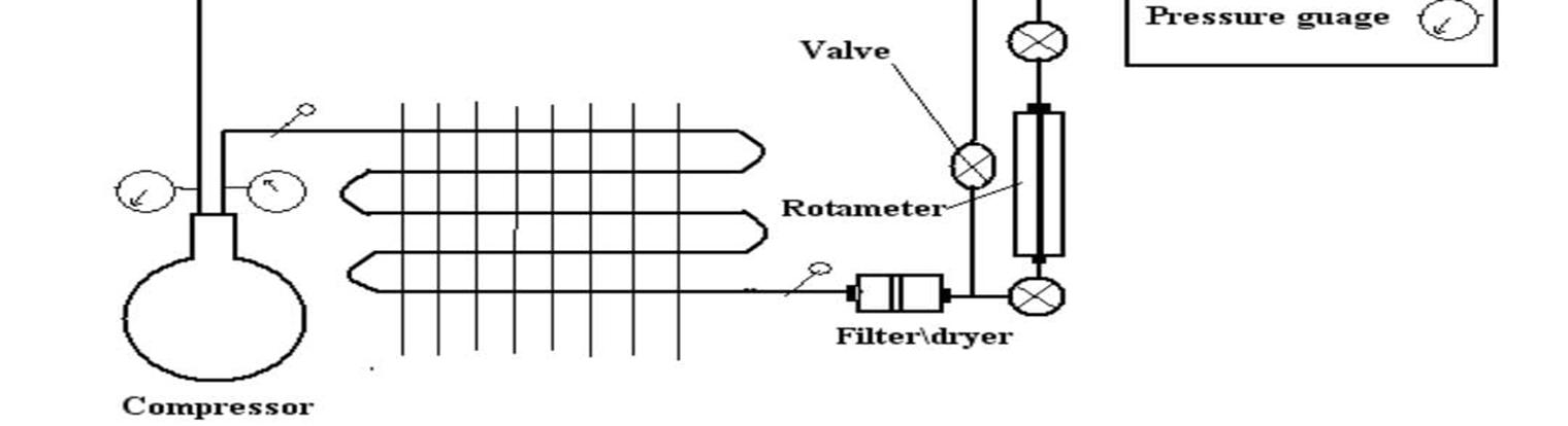
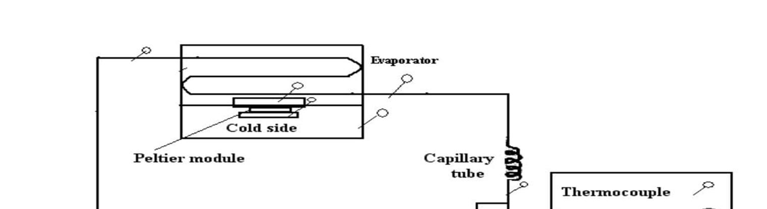
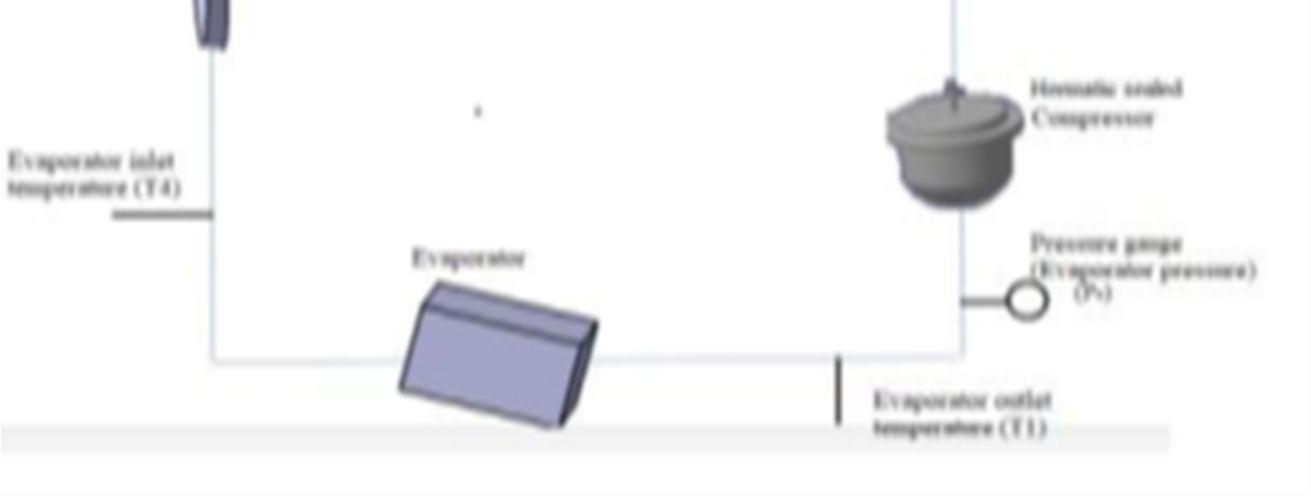
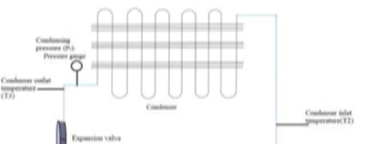
Experimental setups consist of three compartments freezer compartment, thermoelectric compartment and cooler compartment. Thermoelectric compartment is fitted just below the freezer compartment where it has the Peltier plates arranged in such a way that the hot side of the plate comes in contact with the evaporator coiling of vapour compression system. The heat fluxes generated from the plate are absorbed by the evaporator coiling which carry to the compressor. In the system, the topmost and bottom compartment are freezer and cooler compartments, respectively, and are cooled by VCRS. The middle compartment is cooled by thermoelectric material plates. The Peltier plates are arranged in the system in such a way that the heat flux generated by the hot side of the Peltier plate is absorbed by the evaporator coiling just below the freezer compartment. Pressure gauges were installed to record the pressure at the inlet and exit of the compressor. Thermocouples were fixed to record the temperature at the inlet and exit of condenser and evaporator, at hot and cold side of Peltier plate, at freezer compartment, thermoelectrically cooled compartment and the ambient temperature. Rotameter is installed at the exit of the condenser. The rotameter was provided with two valves. The energy meter was used to record the instantaneous power input to the refrigerator and thermoelectric modules. SMPS was used to supply DC power to the Peltier plates and condenser axial fan and the integrated energy consumption of the system.
set
Engineering Technology (IJRASET
ISSN: 2321 9653; IC Value: 45.98; SJ Impact Factor: 7.538 Volume 10 Issue IX Sep 2022 Available at www.ijraset.com
Heat flows naturally from hot to colder body. But, in refrigeration system there is opposite phenomena i.e., heat flows from a cold to a hotter body. This is achieved by using a substance called a refrigerant. The refrigerant (R12) absorbs heat and hence evaporates at a low pressure to form a gas. This gas is then compressed to a higher pressure, such that it transfers the heat it has gained to ambient air or water and turns back (condenses) into a liquid. Thus, heat is absorbed, or removed, from a low temperature source and transferred to a higher temperature source. The refrigeration cycle can be broken down into the following stages as in Fig1.
1) The above review has been studied and it is found out that there are number of processes in VCR system. To obtain the human comforts, less power consumption, to increase the COP of the system
2) The water generator, made from air conditioning and dehumidifier parts, generated an amount of water enough to supply a regular household’s drinking needs.
3) A model test was conducted to investigate the cooling performance of a VCRS protype in warm seasons.
4) Hydrocarbon mixture shows favorable results on theoretical horse power required to drive the compressor. The power required for hydrocarbon mixtures was 38% less than the R 12 refrigerant for same experimental condition.
5) Hydrocarbon mixture shows favorable results on theoretical horse power required to drive the compressor. The power required for hydrocarbon mixtures was 38% less than the R 12 refrigerant for same experimental condition.
6) All the observations and the readings in this simulation will be verified with actual data from the proposed experimental set up.
7) The present study also shows the impact of different parameters which need to be optimized so as to increase the performance
The above review has been studied and it is found out that there are number of processes in VCR system. To obtain the human comforts, less power consumption, to increase the COP of the system.
We express our profound sense of gratitude to our beloved guide Mr.S. VENKATESWARA RAO, Asst Professor, M. Tech, Department of Mechanical Engineering, for his keen guidance and valuable suggestions. We are deeply indebted to him for providing constant support throughout this work. We are grateful to our Head of the Department Dr.K. PRASAD RAO, Professor& Head for his encouragement and providing necessary facilities to complete this term paper. We also thankful to our management for providing such pleasant environment. We also wish to express our deep sense of gratitude to our principal Dr.C. NAGA BHASKAR for his support in completion of this term paper within premises. Last but not least we are thankful to all our staff members and friends who helped us a lot directly or indirectly in successfully completing this term paper.
ISSN: 2321 9653; IC Value: 45.98; SJ Impact Factor: 7.538 Volume 10 Issue IX Sep 2022 Available at www.ijraset.com
[1] Gareth F. Davies, Ian W. Eames, Paul Bailey, Michael W. Dadd, Adam Janiszewski, Richard Stone, Graeme G. Maidment, Cooling Microprocessor Using Vapour Compression Refrigeration, Volume 5, issue no: 978 1 4244 5343 6, DOI: 10.1109/ITHERM.2010.5501390, pg.no. 1 8, 2010.
[2] Dr. G. R. Kannan, K. Tamil Suriya, M. Vidyasagar, M. Vignesh, Comparative Analysis of Vapour Compression Refrigeration System using Various Green Refrigerants, Volume7, ISSN:22780181, DOI: 10.17577/IJERTCONV7IS06047, pg.no. 1 3, 2019.
[3] M. Krishna Prasanna, P. S. Kishore, Enhancement of COP in Vapour Compression Refrigeration System, ISSN: 2278 0181, Vol 3 Issue 11, DOI: 10.17577/IJERTV3IS111404, pg.no. 1535 1539, November 2014.
[4] Dehao Kong, Xiaohong Yin, Xinli Wang2, Xudong Ding3, A model based optimization of vapor compression refrigeration system for energy saving, Vol. 5, Issue 2, ISSN:978 1 7281 7687 1, DOI: 10.1109/CAC51589.2020.9326537, pg.no. 5251 5255, 2020.
[5] T. Anbarasu, S. Pavithra, Vapour Compression Refrigeration System Generating Fresh Water from Humidity in the Air, Volume 8, Issue 10, DOI: 10.1049/cp.2011.0338, pg.no. 75 79, February 2011.
[6] . Qiulin Wang, Tailu Li b, Yanan Jia b, Weiming Zhang, Thermodynamic performance comparison of series and parallel two stage evaporation vapor compression refrigeration cycle, Volume 7, ISSN :2352 4847, https://doi.org/10.1016/j.egyr.2021.03.016, pg.no. 1616 1626, November 2021.
[7] Prateek D. Malwe∗, Juned Shaikh, Bajirao S. Gawali, Exergy assessment of a multistage multievaporator vapor compression refrigeration system using eighteen refrigerants, ScienceDirect, volume 8, ISSN:2352 4847, https://doi.org/10.1016/j.egyr.2021.11.072, pg.no. 153 162, April 2022.
[8] Tianfei Hu, Jiankun Liu, Jian Chang, Zhonghua Hao, Development of a novel vapor compression refrigeration system (VCRS) for permafrost cooling, Cold Regions Science and Technology, ISSN:0165 232x, https://doi.org/10.1016/j.coldregions.2020.103173, 2020.
[9] Dr. S. Periyasamy, M. Saravanan, Experimental Studies on a Vapour Compression Refrigeration System using Hydrocarbon Mixtures and R 12 Refrigerant, Vol. 3 Issue 5, ISSN: 2278 0181, DOI: 10.17577/IJERTV3IS050581, pg.no. 1070 1073, 2014.
[10] Kalpesh Patil, Gauri Thorat, Mathewlal T, Numerical Simulation of Vapour Compression Refrigeration System, Volume 3 Issue 01, ISSN: 2278 0181, DOI: 10.17577/IJERTCONV3IS01041, pg.no. 1 5, 2015