
10 X October 2022 https://doi.org/10.22214/ijraset.2022.46941
ISSN: 2321 9653; IC Value: 45.98; SJ Impact Factor: 7.538
Volume 10 Issue X Oct 2022 Available at www.ijraset.com

ISSN: 2321 9653; IC Value: 45.98; SJ Impact Factor: 7.538
Volume 10 Issue X Oct 2022 Available at www.ijraset.com
Tarun Kumar1, Hamid Ali2
1PG Student, 2Asst. Prof., Department of Electronics and Communication Engineering, Shobhit University, Gangoh, India
Abstract: Modern telecommunication systems require antenna with wider bandwidth and smaller dimensions. Various antennas for wideband operation have been studied for communication and radar system. The fractal antennas are preferred due to small size, light weight and easy installation. In this paper a parabolic planer monopole antenna using the Koch based fractal geometry is introduced for multiband operation. The design achieves a good input impedance match and linear phase of S11 throughout the pass band (1 3.5 GHz and 10dB criterion for impedance bandwidth). The use of fractal pattern in this paper provides a simple and efficient method for obtaining the compactness. Various bands are 1.2GHz and 2.3 GHz. The antenna has a promising peak gain of 5.3 dBi with 5.5 dBi directivity in pass band. The pass band has VSWR in between 1 and 2. The proposed antenna has enormous high bandwidth (1.124GHz) that suits the many wireless applications like WLAN, Bluetooth, analog radio and GPS system and it can also be used for microwave devices communication.
Index Terms: Koch fractal, parabolic antenna, Bluetooth
The current upsurge in wireless communication systems has forced antenna engineering to face new challenges, which include the need for small size, high performance, low cost antennas. Miniature antennas are prime importance due to the available space limitation on the devices and the oncoming deployment of diversity and multiple input multiple output (MIMO) system. The basic antenna miniaturization techniques can be summarized into lumped element loading, material loading, and use of ground planes, short circuits, the antenna environment and finally geometry optimization [1]. Among these techniques, geometry optimization and the use of ground planes can achieve miniaturization while maintaining good antenna performance, especially in term of bandwidth and efficiency [2]
The main objective of this paper is to design a parabolic shaped fractal antenna which will be small in size and for multiband operation with high gain and enhanced bandwidth. For gain and bandwidth enhancement a finite ground plane is used. For reducing the size of antenna, fractal geometries have been introduced.

Fractals were defined Benoit Mendelbort in 1975. A fractal is “a rough or fragmented geometric shape” that is generated by starting with a very simple pattern that grows through the application of rules. In many cases the rules to make the figure grow from one stage to next involve taking the original figure and modifying it or adding to it. The process can be repeated recursively an infinite number of times. Fractal geometries have two common properties: self similar property, space filling property. The self similarity property of certain fractals results in a multiband behavior. Using the self similarity properties, a fractal antenna can be designed to receive and transmit over a wide range of frequencies. While using space filling properties, a fractal make reduce antenna size. Fractal antenna engineering is the field which utilizes fractal geometries for antenna design. Antenna miniaturization has been the subject of numerous studies for almost 70 years. Early studies showed that a decrease in the size of an antenna results in a direct reduction in its bandwidth and efficiency. Recently, many new investigations has been conducted to reduce the form factor (the overall size) of different types of antennas while trying to maintain acceptable matching property and bandwidth. It has become one of the growing fields of antenna engineering due to its advantages over conventional antenna design.
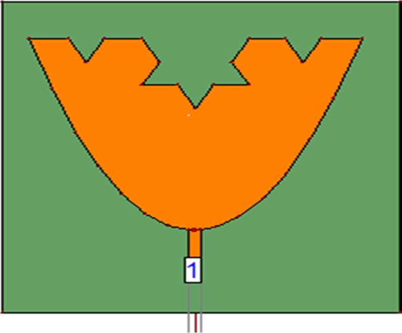
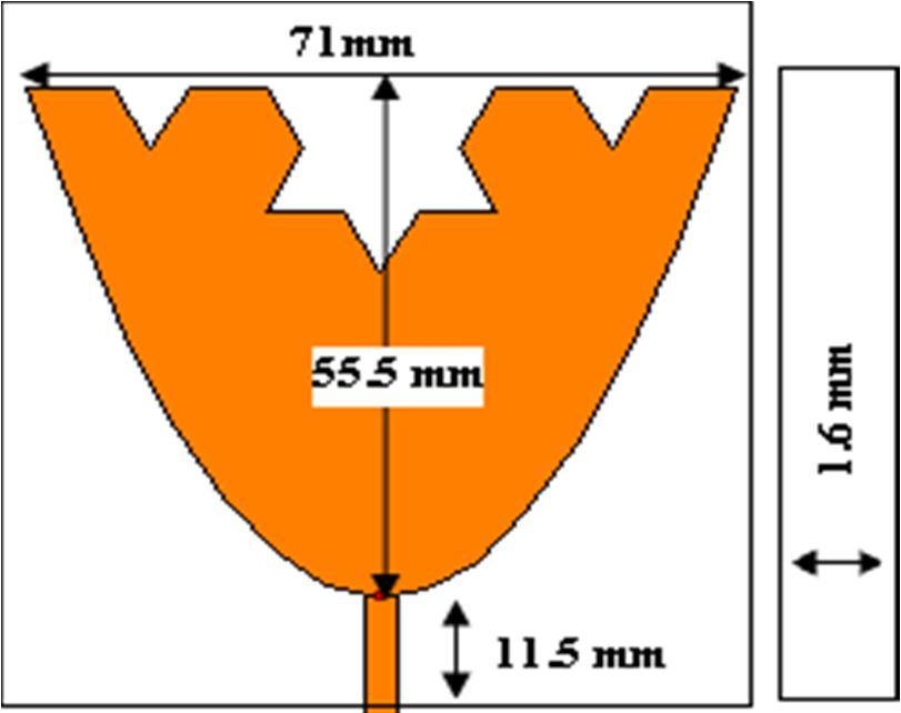
The proposed antenna as depicted by figure1 is designed by using the concept of Koch fractal structure in parabolic shaped planer patch geometry. It is printed on the FR4_epoxy substrate of 4.4 dielectric permittivity and 0.02 tangent losses. It is fed through a 50Ω impedance characteristics feed line. The antenna is designed by using the parabolic patch and the Koch fractal. We use y=0.044x2 equation for the parabolic curve [1].

ISSN: 2321 9653; IC Value: 45.98; SJ Impact Factor: 7.538 Volume 10 Issue X Oct 2022 Available at www.ijraset.com
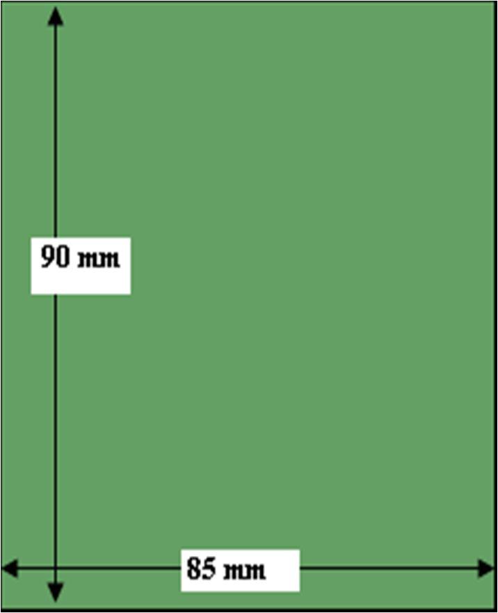
The dimension of substrate layer is of Lsub=67 mm length and Wsub=71mm width and h=1.6mm thick and it is backed by a finite ground plane of dimension 85 x 90 mm. On the top of parabola structure, an inverted koch fractal of second order has been used in this paper.
ISSN: 2321 9653; IC Value: 45.98; SJ Impact Factor: 7.538 Volume 10 Issue X Oct 2022 Available at www.ijraset.com

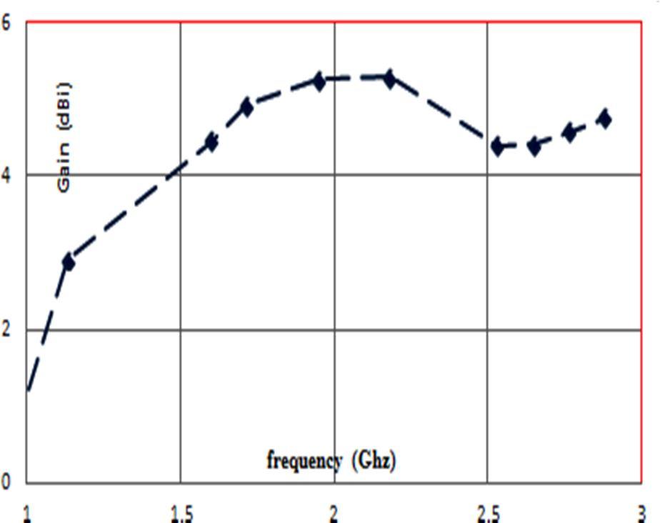
Figure2. Return Loss characteristics of parabolic fractal antenna
The proposed antenna has the combined effect of parabolic structure as well as Koch fractal. The antenna used the second order fractal that signifies the dual band resonance at lower band of operation. The simulated result (return loss) of proposed antenna is shown in figure (2). The antenna has promising return losses of 21 dB to 29dB at the resonance frequencies in pass band. The peak gain of in the pass band is 5.3 dBi. The variation of gain vs frequencies is shown in figure (3). The directivity of antenna at different frequencies is shown in figure (5). Figure (4) shows the VSWR characteristics of a parabolic fractal antenna.
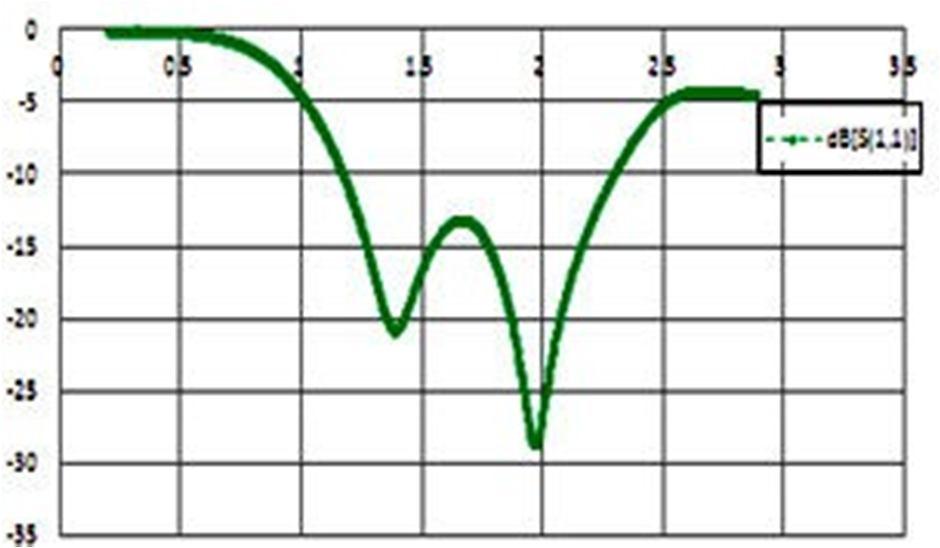
Figure3. Gain variation of parabolic fractal antenna
Figure4. VSWR characteristics of parabolic fractal antenna
ISSN: 2321 9653; IC Value: 45.98; SJ Impact Factor: 7.538 Volume 10 Issue X Oct 2022 Available at www.ijraset.com
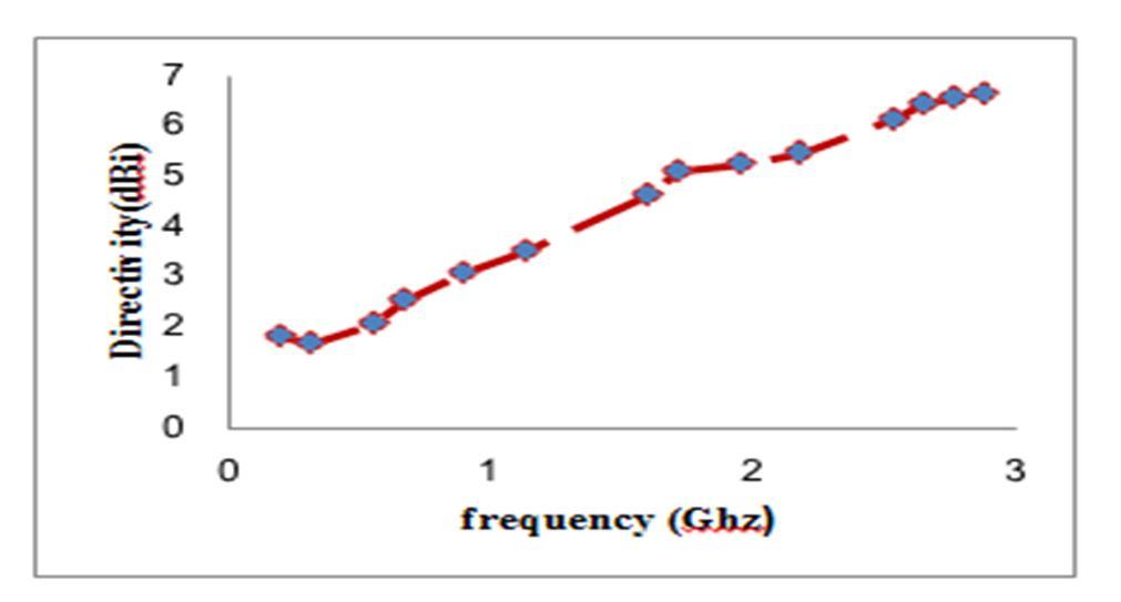
Figure5. Directivity characteristics of parabolic fractal antenna
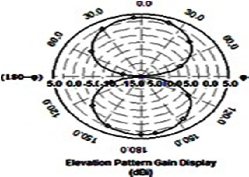
(a) fr= 1.34 GHz
(b) fr= 1.94 GHz
Figure6. Elevation pattern at (φ= 0 & φ=90) of patch
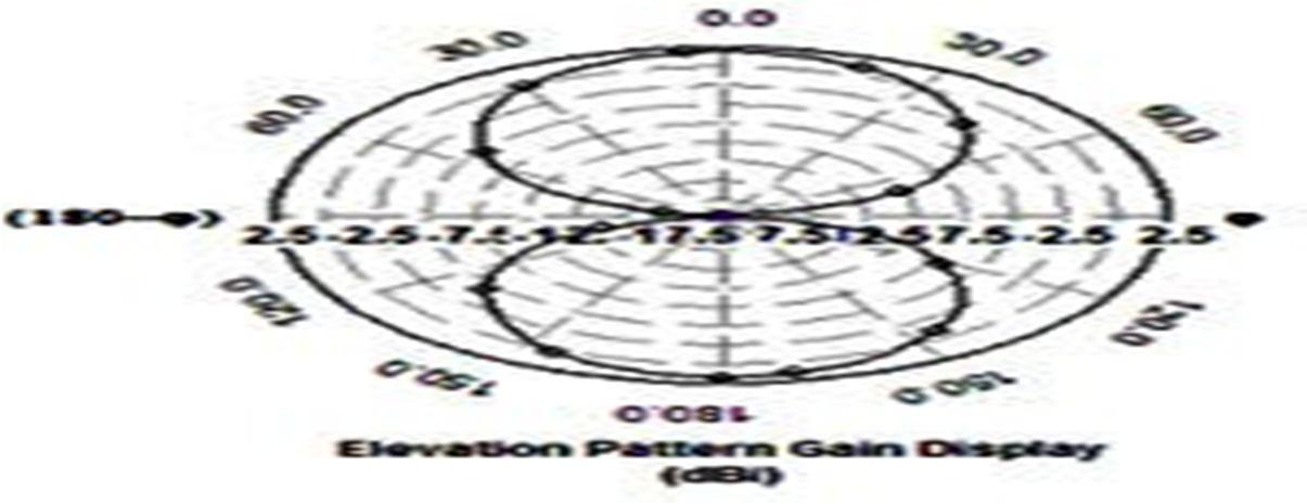
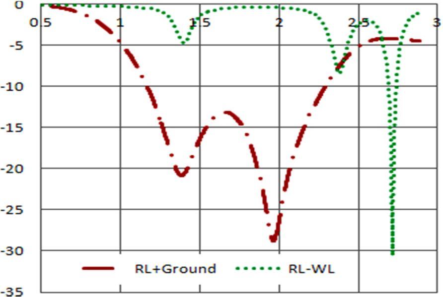
Figure7. Effect of finite ground on Return Loss
Radiation pattern is shown in figure (6)
ISSN: 2321 9653; IC Value: 45.98; SJ Impact Factor: 7.538 Volume 10 Issue X Oct 2022 Available at www.ijraset.com
The designed simulated results show that it has very good impedance characteristics in the pass band 1.2 to 2.3 Ghz. Its 1100 MHz bandwidth makes it to fit in current wireless and multiple applications. Its large bandwidth in lower band makes it suitable for Bluetooth, radio as well wireless USB applications.
(a) fr= 1.94 GHz
(b) fr= 1.34GHz
Figure 8.3 D Radiation Pattern of proposed geometry
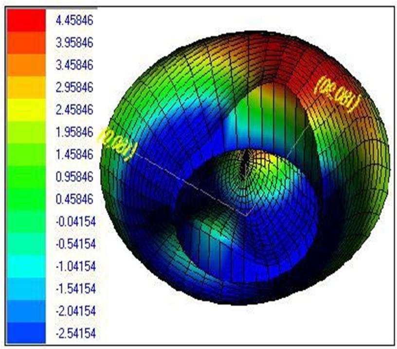
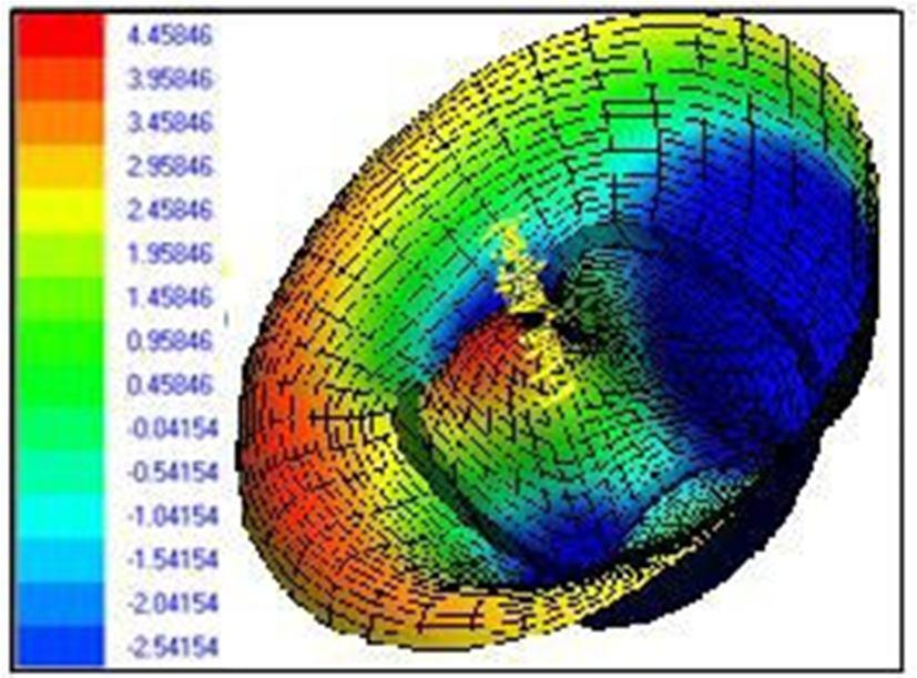
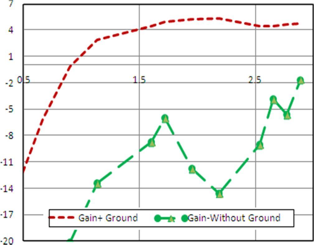
Figure9. Effect of finite ground on Gain
ISSN: 2321 9653; IC Value: 45.98; SJ Impact Factor: 7.538 Volume 10 Issue X Oct 2022 Available at www.ijraset.com
[1] A.K. Skrivervik, J. F. Zurker, O. Staub and J.R. Mosig, PCS antenna design: The challenge of Miniaturization, IEEE Antennas Propagat Mag 43(2001), 12 26.
[2] H. Morishita, Y. Kim and K. Fujimoto, Design concepts of antennas for small mobile terminals and the future perspective, IEEE Antennas Propagat Mag 44(2002),0 43.
[3] Choi, S., H., J. K. Park, S. K. Kim, and J. Y. Park, “A new ultra wide band antenna for uwb application," Microwave and Optical Technologies Letters, Vol. 40, No. 5, March 5, 2004.
[4] Eldek, A. A., “A broadband double dipole antenna with triangle and rhombus shapes and stable end fire radiation patterns for phased array antenna systems," Microwave Journal, Jackson State University, October 2006.
[5] Sldovieri, F., G. Prisco, A. Brancaccio, and G. Leone, “Characterization of ultra wideband bow tie antennas for ground penetrating radar systems," Microwave Journal, Vol. 49, No. 8, Pharmaceutical News Index page 186, August 2006.
[6] Jang, Y. W., “Characteristics of a wide band, high element characteristics of a wide band, high gain, eight element slot antenna for Pcs, Imt 2000 and Wll band," Microwave Journal, Keukdong College, Chungcheongbuk Do, Korea, June 2004.
[7] Cohen, N. (Summer 1995). "Fractal Antennas".Communications Quarterly: 9.
[8] Balanis C.A., “Antenna Theory: Analysis and Design”, Second Edition, New York, John Wiley& Sons, Inc., 2003.
[9] John P. Gianvittorrio and Yahya Rahmat samii, “Fractal Antennas: A Novel Antenna Miniaturization Technique and Applications”, IEEE Antenna and Propagation Magazine, pp. 20 36, 44 (1), 2002.