
1
ISSN: 2321 9653; IC Value: 45.98; SJ Impact Factor: 7.538
Volume 10 Issue X Oct 2022 Available at www.ijraset.com


1
ISSN: 2321 9653; IC Value: 45.98; SJ Impact Factor: 7.538
Volume 10 Issue X Oct 2022 Available at www.ijraset.com

Abstract: Conventional steel frames are low rise steel frames with roofing systems of truss and roof coverings. Standard hot rolled sections are used for truss elements which are usually much heavier than what is actually required as per the design. Pre Engineered steel frames are the steel frames in which excess steel is tapered as per the bending moment requirements. In present study, conventional (pratt type) steel roof truss and pre engineered (portal type) steel roof frame with crane load is considered for an industrial warehouse construction located in Davangere city. 2D Modelling of both conventional and pre-engineered steel frame with crane load is done using STAAD Pro. software. Both the steel frames are subjected to different combinations of Dead load (DL), Live load(LL), Crane Load(CL) and Wind load(WL) as per IS 800 (2007) codal provisions. For the factored bending moments and shear force, referring IS 800 (2007) codal provisions, crane gantry girder is designed as a laterally unsupported member having a combination of I and channel sections. The members of both conventional and pre engineered steel frames with crane load are designed for the worst load combination as per IS 800(2007) codal provisions. It is concluded that about 25% reduction in quantity of steel can be achieved by choosing pre engineered steel frame than the conventional steel frame.
Keywords: CSB, PEB, CL, STAAD Pro.
Steel is one of the most commonly used building materials, as it plays the most prominent role especially in industrial sector and where there is a need of faster rate of construction over a huge area. Industries require larger area as there is a usage of heavy equipment and machines. Even steel structures are used to transport the goods from one place to another within the warehouse by using cranes. As steel is strong, hard, and ductile and fire resistive material, it is very suitable for rapid construction especially in industrial sector. One more advantage of steel structures is it can be easily dismantled and shifted to anywhere around the site. Design of steel structures contains design of secondary members like bracings, tie rods, column base, purlins etc. Roof truss used in factories, cinema halls, transmission towers, chimney, warehouses, railways, crane girder, bridges etc. Are some of the steel structures. In the present study, both csb and peb frames are considered subjected to crane load. Dead load(dl), live load(ll), wind load(wl) and different load combinations are applied and designed both the frame for the worst load combinations. Crane load is also calculated by manual calculations and added to the supporting columns. Last part of the paper depicts the quantity of steel required for both the frames and the comparison between the cost. The paper aims at explaining the advantages of using peb over csb.

In the present paper, conventional (i.e. Pratt truss) and Pre Engineered (i.e. portal type) industrial steel frames subjected to crane load are considered for an industrial building located at Davangere City. Dead Load (DL), Live Load (LL), Crane Load(CL) and Wind Load (WL) are applied on both the frames as per IS 875 Part 1 (1987), IS 875 Part 2 (1987) and IS 875 Part 3 (2015) codal provisions respectively. The developed 2D models are analysed using STAAD Pro. software for various load combinations as specified by IS 800 (2007) codal provisions. The members of both the frames are designed for the worst load combination as per IS 800 (2007).
The total mass of steel required for both the conventional and Pre Engineered steel frames(except the mass of connections, purlins and crane) is calculated and cost comparison is made to check the economy achieved in using Pre Engineered steel frames over the conventional steel frames.
ISSN: 2321 9653; IC Value: 45.98; SJ Impact Factor: 7.538 Volume 10 Issue X Oct 2022 Available at www.ijraset.com

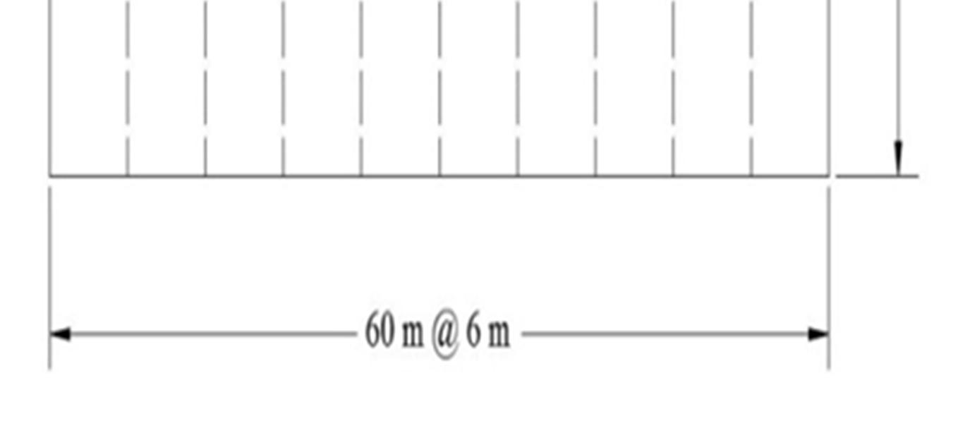
Conventional and Pre Engineered steel frames suitable for Davangere city is considered for modelling in STAAD Pro. software. Table 1 shows the details of conventional and Pre Engineered steel frames subjected to crane load. Figure 1 shows the plan details of Conventional and Pre Engineered steel frames.
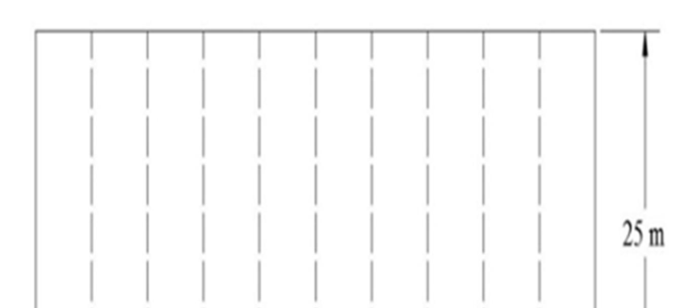
Table 1: Details of conventional and pre engineered steel frames
Sl. No.

Parameter Dimension Remarks 1 Plan dimension 60 × 25 m 2 Height of supporting columns 10 m 3 Rise of frame 3 m 4 Spacing of frames 6 m Spacing of frame in the range of 1/4th to 1/5th of span length 5 Slope of roof 13.5º tan 1 6 Number of bays 11 Length Spacing +1 7 Type of roofing Galvanized iron sheeting 8 Spacing of purlins 3.21 m Slantrooflength No ofNodes 9 Type of support condition for columns Hinged 10 Type of Truss Pratt 11 Type of Pre Engineered Frame Portal type
Fig. 1: Plan of conventional and pre engineered steel frame
ISSN: 2321 9653; IC Value: 45.98; SJ Impact Factor: 7.538

Volume 10 Issue X Oct 2022 Available at www.ijraset.com
Table 2 shows the details of electric overhead traveling crane gantry girder considered in the present study.
Table.2: Details of gantry girder
Sl. No. Parameter Value 1
Span of the crane girder 25 m 2 Span of gantry girder 6 m 3 Capacity of crane 200 kN 4 Self weight of crane excluding crab 160 kN 5 Weight of crab 75 kN 6 Wheel base distance 3.5 m 7 Minimum hook approach 0.9 m 8 Self weight of rail 0.4 kN/m 9 Height of rail 60 mm 10 Total height of supporting columns 10 m 11 Position of gantry girder from base of column 6 m

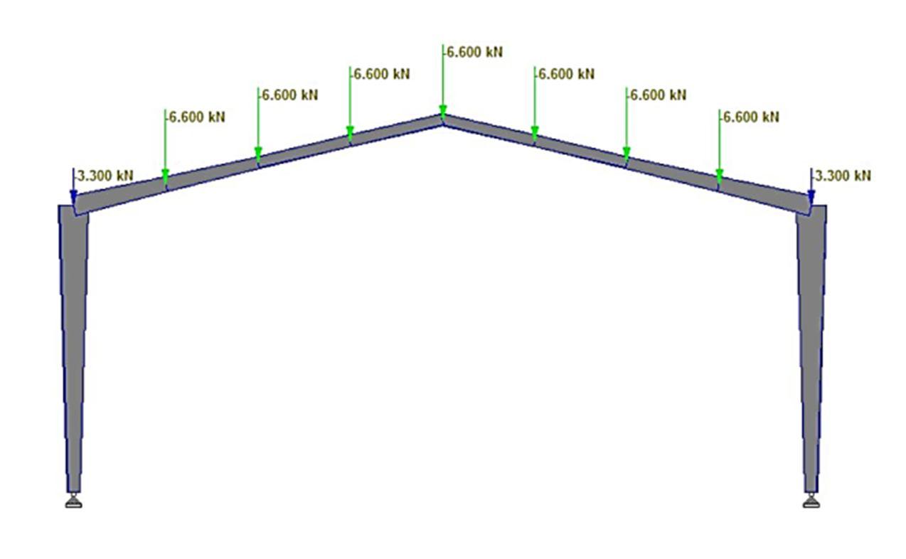
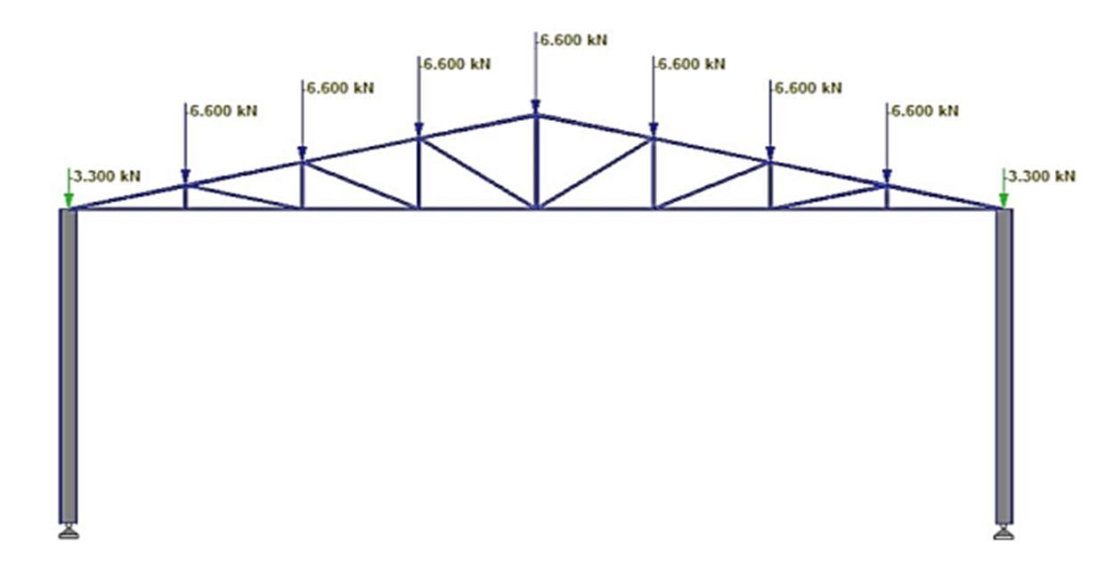
1) Calculation of Dead Load (DL): Dead loads acting on the frames are calculated as per IS 875 Part 1 (1987) which includes the loads of roofing materials, purlins and trusses. Figures 2 and 3 respectively show the application of dead loads acting at the purlin positions of conventional and Pre Engineered steel frames.
Fig.2: Dead loads acting at the purlin positions of conventional steel frame
Fig.3: Dead loads acting at the purlin positions of pre engineered steel frame
ISSN: 2321 9653; IC Value: 45.98; SJ Impact Factor: 7.538 Volume 10 Issue X Oct 2022 Available at www.ijraset.com

2) Calculation of Live Load (LL): Live loads acting on the frames is calculated as per IS 875 Part 2 (1987).
Figures 4 and 5 shows the application of live loads acting at the purlin positions of conventional and pre engineered steel frames.
Fig. 4: Live loads acting at the purlin positions of conventional steel frame
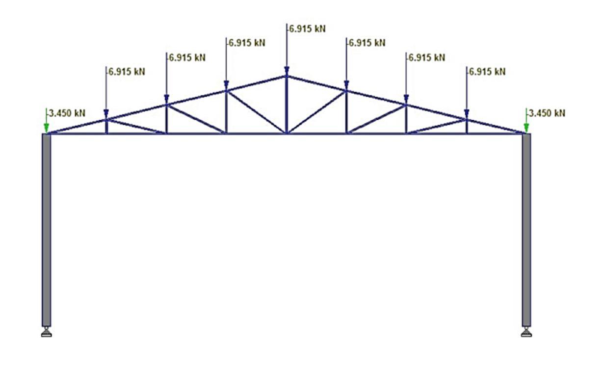
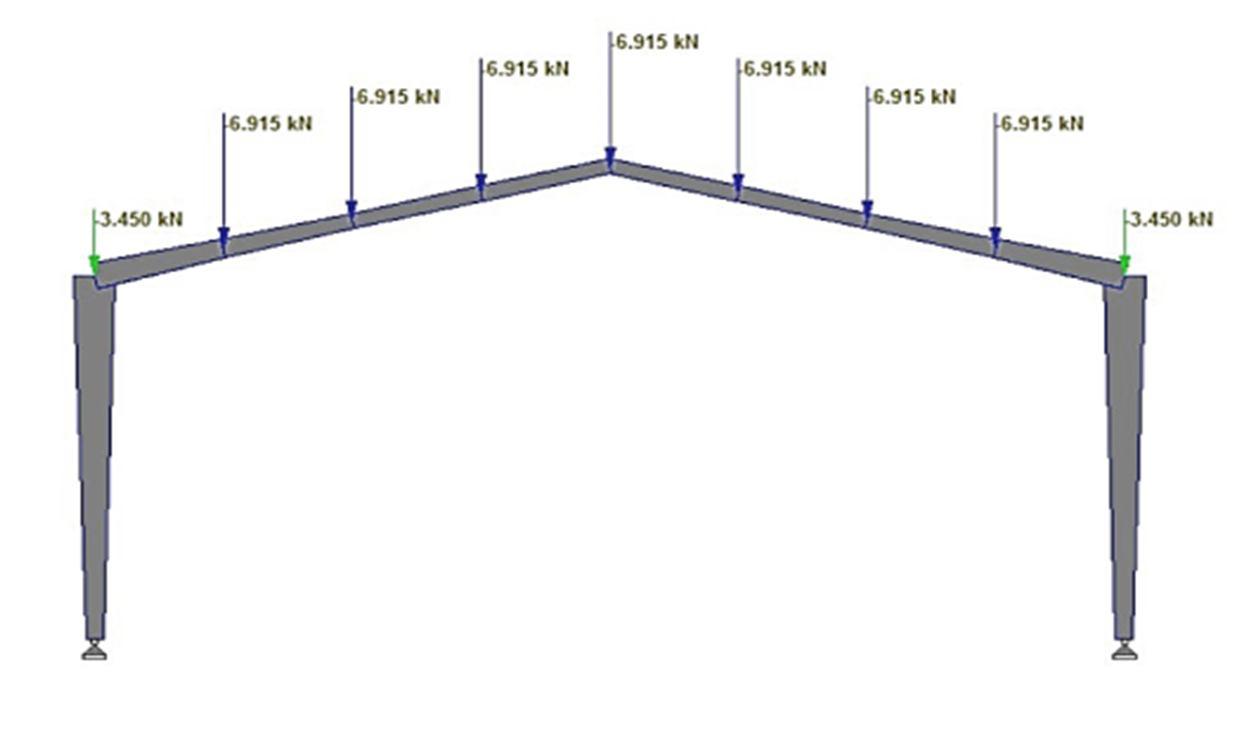
Fig. 5: Live loads acting at the purlin positions of pre engineered steel frame
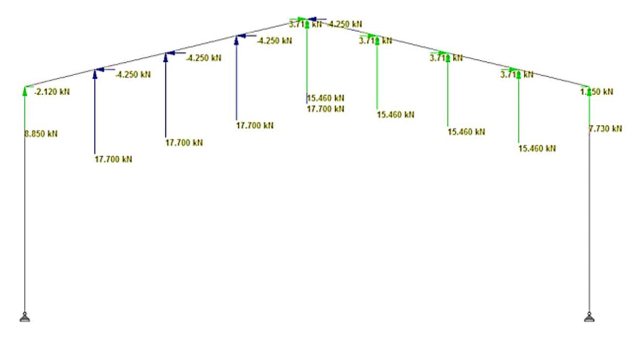
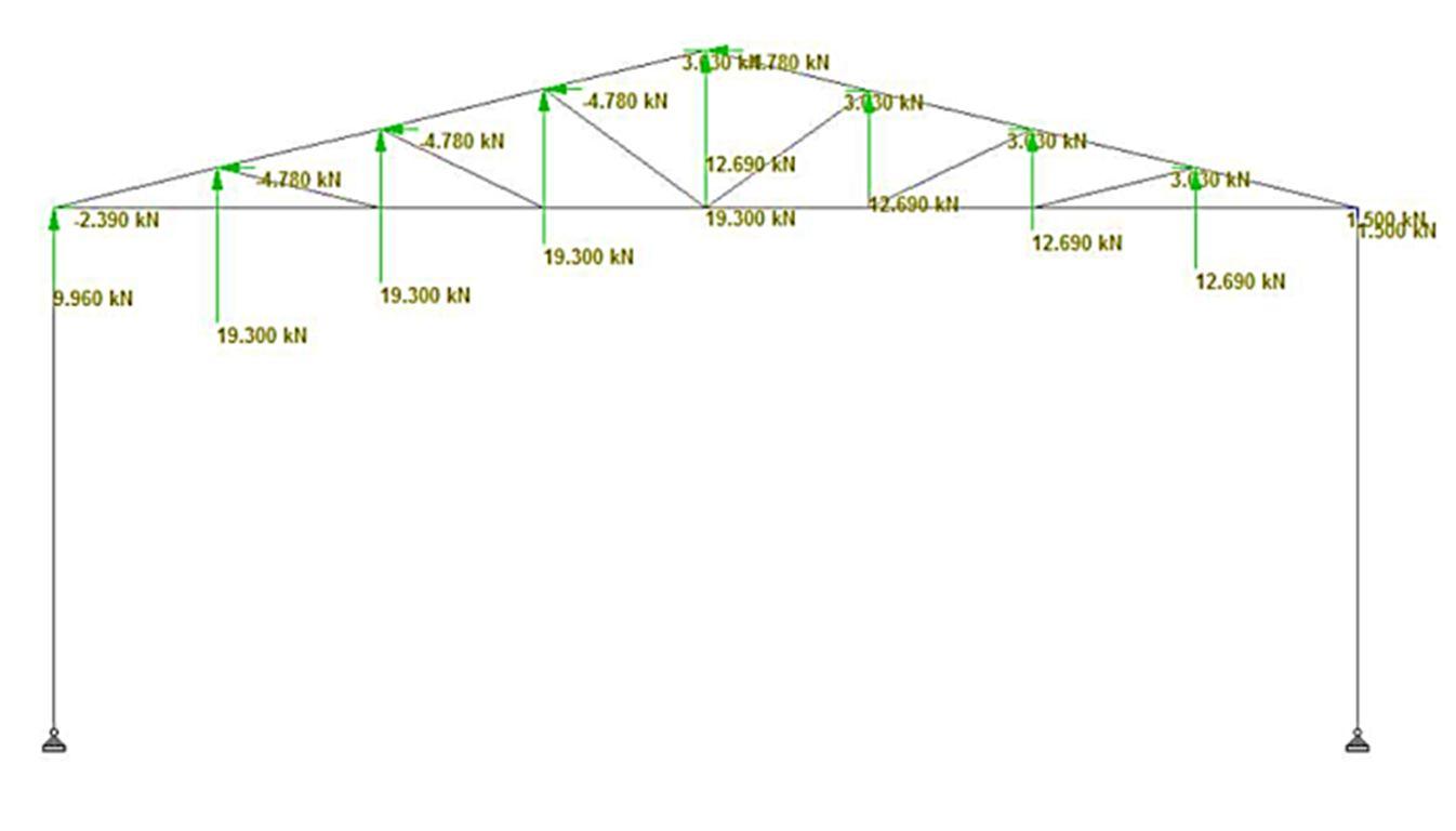
3) Calculation of Wind Load (WL): Wind loads acting on both conventional and pre engineered steel frames subjected to crane load are calculated as per IS 875 Part 3(2015). Table 3 shows the wind loads acting on both frames. Figures 6 and 7 respectively show the application of wind loads (considering wind angle 0º) at the purlin positions of both conventional and pre engineered steel frames.

Table 3: Wind loads acting on conventional and pre engineered steel frame for wind angle 0° and 90° Wind angle Pressure coefficients Cpe± Cpi Area X Pd (kN) WW (kN) LW (kN) WW LW Cpi WW LW
0° 0.92 0.4
0.5 1.42 0.9 14.45 20.5 13 +0.5 0.42 0.1 14.45 6.07 1.44 90° 0.76 0.6 0.5 1.23 1.1 14.45 18.2 15.9 +0.5 0.23 0.1 9.13 3.75 1.4
Note: WW: Windward, LW: Leeward.
ISSN: 2321 9653; IC Value: 45.98; SJ Impact Factor: 7.538


Volume 10 Issue X Oct 2022 Available at www.ijraset.com

Fig. 6: Wind loads acting at the purlin positions of conventional steel frame for wind angle 0º
Fig. 7: Wind loads acting at the purlin positions of pre engineered steel frame for wind angle 0º
Figures 8 and 9 respectively show the application of wind loads (considering wind angle 90º) at the purlin positions of both conventional and pre engineered steel frames.
Fig. 8: Wind loads acting at the purlin positions of conventional steel frame for wind angle 90º

ISSN: 2321 9653; IC Value: 45.98; SJ Impact Factor: 7.538


Volume 10 Issue X Oct 2022 Available at www.ijraset.com
Fig. 9: Wind loads acting at the purlin positions of pre engineered steel frame for wind angle 90º


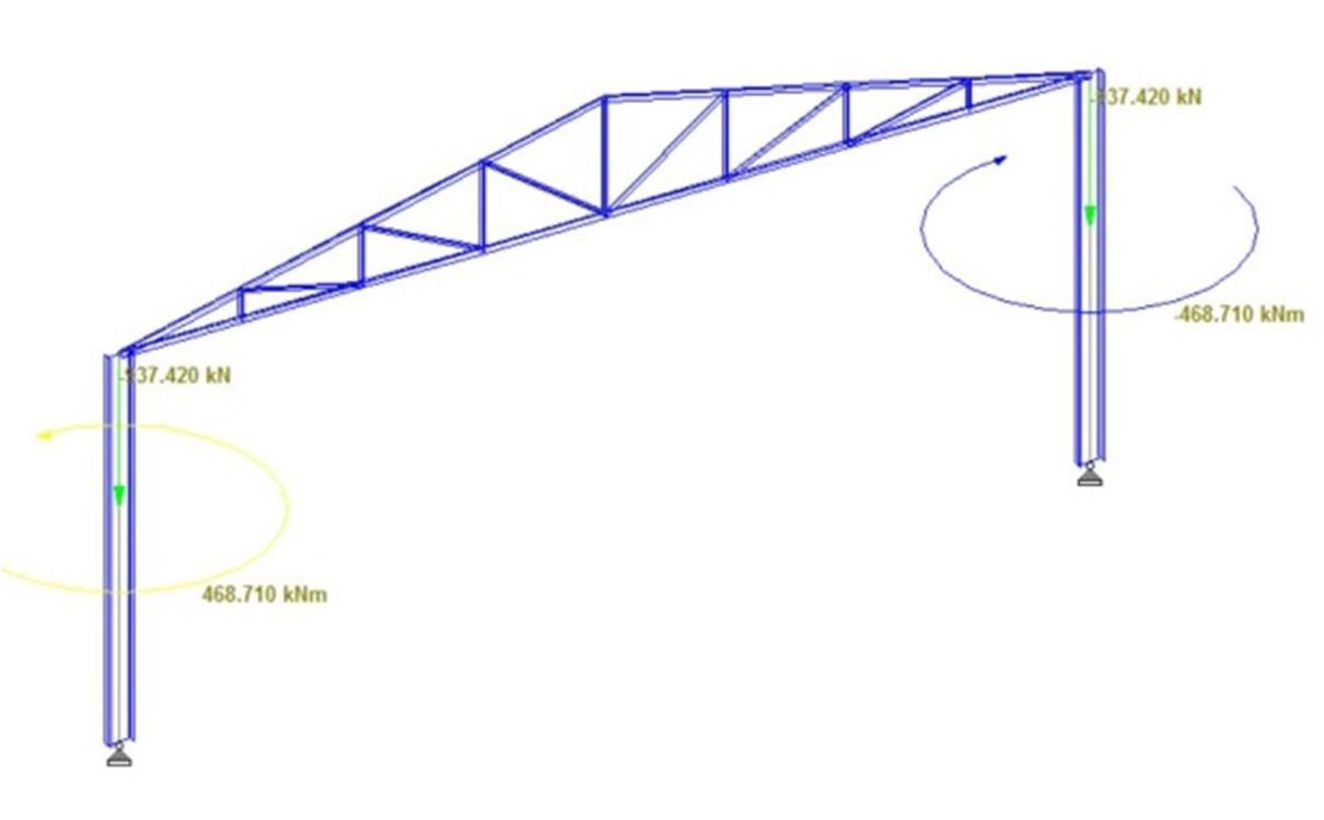
4) Calculation of loads on Crane Gantry Girder: Gantry girder is assumed to be simply supported on bracket plates that are attached to the supporting column flanges. Figures 10 and 11 respectively show the factored load and couple moment acting on supporting columns of conventional and pre engineered steel frames
Fig. 10: Factored load and couple moment acting on supporting columns of conventional steel frame
Fig. 11: Factored load and couple moment acting on supporting columns of pre engineered steel frame
ISSN: 2321 9653; IC Value: 45.98; SJ Impact Factor: 7.538 Volume 10 Issue X Oct 2022 Available at www.ijraset.com


Figure 12 shows the member numbers of the conventional steel frame subjected to crane load, as specified by STAAD Pro. software.
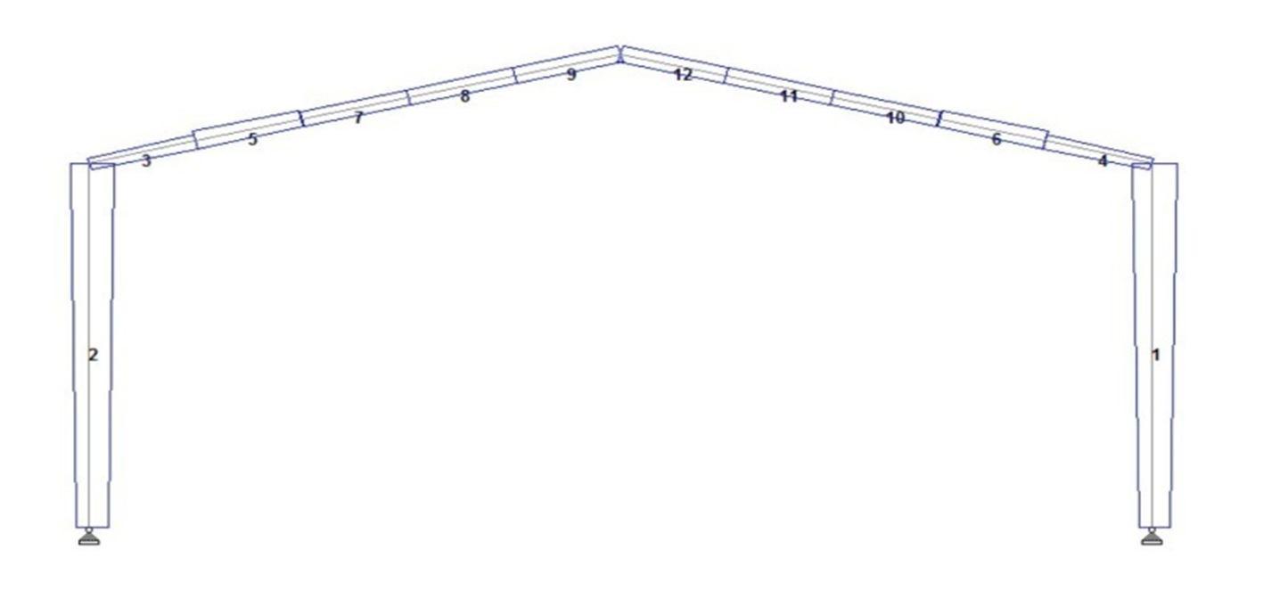

Fig. 12: Member numbers of conventional steel frame
Table 4 shows the details of sectional properties of the members of conventional steel frame considered for modelling in STAAD Pro. software
Table 4: Details of member sectional properties of conventional steel frame Sl. No. Members Member No Size
1
Top Chord Members 3, 6, 10, 14, 18, 22, 26 and 30
2 ISA 150×150×18 @ 39.3 kg/m
2 Bottom Chord Members 2, 5, 9, 13, 17, 21, 25 and 29 2ISA150×150×12 @ 27.2 kg/m
3 Inner Members 4, 7, 8, 11, 12, 15, 16, 19, 20, 23, 24, 27 and 28 2ISA110×110×12 @ 19.6 kg/m
4 Columns 1 and 31 ISWB 600 @ 133.7 kg/m
Figure 13 shows the member numbers of the pre engineered steel frame subjected to crane load, as specified by STAAD Pro. software.
Fig. 13 : Member numbers of pre engineered steel frame

ISSN: 2321 9653; IC Value: 45.98; SJ Impact Factor: 7.538

Volume 10 Issue X Oct 2022 Available at www.ijraset.com
Details of sectional properties of the members of pre engineered steel frame subjected to crane load considered for the analysis in STAAD Pro. is shown in Fig. 14
Fig. 14: Details of sectional properties of pre engineered steel frame
Tables 5 and 6 respectively show the description and sectional properties of the pre engineered steel frame.
Table 5: Description of typical sectional properties of the pre engineered steel frame Sl. No Notation Description
1 F1 Depth of section at start node 2 F2 Thickness of web 3 F3 Depth of section at end node 4 F4 Width of top flange 5 F5 Thickness of top flange 6 F6 Width of bottom flange
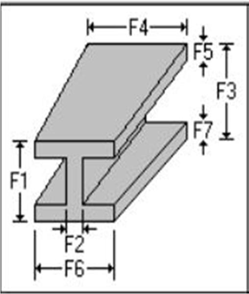
Table 6: Details of sectional properties of the members of pre engineered steel frame Sl. No. Notat ion
Member 1 (m)
Member 2 (m)
Member 3 (m)
Member 4 (m)
Member 5 (m)
Member 6 (m)
Member 7 (m)
Member 8 (m)
Member 9 (m)
Member 10 (m)
1 F1 1.016 1.016 0.716 0.516 0.416 0.416 0.716 0.516 0.416 0.416
2 F2 0.01 0.01 0.01 0.01 0.01 0.01 0.01 0.01 0.01 0.01
3 F3 0.416 0.416 0.516 0.416 0.416 0.416 0.516 0.416 0.416 0.416
4 F4 0.3 0.3 0.3 0.25 0.25 0.25 0.3 0.25 0.25 0.25
5 F5 0.008 0.008 0.008 0.008 0.006 0.006 0.008 0.008 0.008 0.008

6 F6 0.3 0.3 0.3 0.25 0.25 0.25 0.3 0.25 0.25 0.25
7 F7 0.008 0.008 0.008 0.008 0.008 0.008 0.008 0.008 0.008 0.008
Both conventional and pre engineered steel frames are modelled in STAAD Pro. software. DL, LL, WL, and factored crane gantry girder point load and couple moment are applied. Following load combinations as per Table 4 of IS 800 (2007) are considered during 2D analysis.
1) 1.5DL + 1.5LL
2) 1.5DL + 1.5 WL 0
3) 1.5DL + 1.5 WL 90
4) 1.5DL 1.5 WL 0
5) 1.5DL 1.5 WL 90 DL+LL+WL combinations are not critical as wind load acts in opposite direction to DL and LL (INSDAG Manual).
ISSN: 2321 9653; IC Value: 45.98; SJ Impact Factor: 7.538 Volume 10 Issue X Oct 2022 Available at www.ijraset.com

The design of all members of conventional steel frame is done for the worst load combination as predicted by STAAD pro. Software.
A. Design Of Crane Gantry Girder
Table 7 shows the sectional properties of gantry girder.
Table 7: Sectional properties of gantry girder Sectional Property ISMB 600 @1230 N/m ISMC 300 @ 358 N/m Area (mm2) 15621 4564 Depth (mm) 600 300 Breadth (mm) 210 90 Thickness of flange (mm) 20.8 13.6 Thickness of web (mm) 12 7.6
Moment of Inertia, Izz (mm4) 91813 x 104 6362.6 x 104 Moment of Inertia, Iyy(mm4) 2651 x 104 310.8 x 10⁴
Section Modulus, Zzz(mm3) 3060 x 103 424.2 x10³
Table 8 shows the maximum axial forces (Fx, tension and compression) developed on the top chord members, obtained from STAAD Pro. software
Table 8: Maximum axial forces (Fx) acting on the top chord members of conventional steel frame Top Chord Members Node Fx (kN) Load Combination 3
Start 692.5 1.5DL 1.5WL 0 End 324.96 1.5DL+1.5WL 0 6
Start 578.26 1.5DL 1.5WL 0 End 258.95 1.5DL + 1.5 WL 0 10 Start 481.79 1.5DL 1.5 WL 90 End 214.6 1.5DL + 1.5 WL 90 14 Start 397.6 1.5DL 1.5WL 90 End 179.2 1.5DL + 1.5WL 90 18
Start 398.2 1.5DL 1.5WL 90 End 179.8 1.5DL + 1.5WL 90 22
Start 471.53 1.5DL 1.5WL 90 End 207.3 1.5DL + 1.5WL 90 26
Start 541.06 1.5DL 1.5WL 90 End 234.2 1.5DL + 1.5WL 90 30
Start 552.8 1.5DL 1.5WL 90 End 231.83 1.5DL + 1.5WL 90
2 ISA 150 ×150 × 18 @ 39.9 kg/m is taken for the analysis
C. Design of Bottom Chord Members
Table 9 shows the maximum axial forces (Fx, tension and compression) developed on the bottom chord members, obtained from STAAD Pro. software

Applied Science & Engineering Technology (IJRASET

ISSN: 2321 9653; IC Value: 45.98; SJ Impact Factor: 7.538 Volume 10 Issue X Oct 2022 Available at www.ijraset.com
Table 9: Maximum axial forces (Fx) acting on the bottom chord members of conventional steel frame Bottom Chord Members Node Fx (kN) Load Combination 2
Start 278.85 1.5DL + 1.5 WL 0 End 673.81 1.5DL 1.5WL 0 5 Start 308.45 WL 0 End 664.5 1.5DL 1.5 WL 0 9 Start 247.1 WL 0 End 538.06 1.5DL 1.5 WL 0 13 Start 198.9 WL 0 End 452.26 1.5DL 1.5WL 90 17 Start 190.27 WL 90 End 439.9 1.5DL 1.5WL 90 21 Start 219.3 WL 90 End 511.6 1.5DL 1.5WL 90 25 Start 229.3 WL 90 End 545.8 1.5DL 1.5WL 90 29 Start 219.7 WL 90 End 527.1 1.5DL 1.5 WL 90
2 ISA 150 ×150 × 18 @ 39.9 kg/m is taken for the analysis.

Table 10 shows the maximum axial forces (Fx, tension and compression) developed on the inclined members, obtained from STAAD Pro. software.
Table 10: Maximum axial forces (Fx) acting on the inclined members of conventional steel frame Inclined Members Node Fx (kN) Load combination 4
Start 9.7 1.5DL 1.5WL 90 End 7.2 1.5DL + 1.5WL 90 7 Start 114.1 1.5DL 1.5WL 0 End 76.4 1.5DL + 1.5 WL 90 8 Start 14.45 1.5DL + 1.5 WL 0 End 29.60 1.5DL 1.5 WL 0 11 Start 112.03 1.5DL 1.5WL 0 End 53.26 1.5DL + 1.5WL 0 12 Start 23.09 WL 0 End 51.4 1.5DL 1.5WL 0 15 Start 120.83 1.5DL 1.5WL 90 End 55.7 1.5DL + 1.5WL 0 16 Start 50.27 WL 90 End 122.5 1.5DL 1.5WL 90 19 Start 94.6 1.5DL 1.5WL 90 End 38.05 1.5DL + 1.5WL 90 20 Start 13.5 1.5DL + 1.5WL 90 End 28.05 1.5DL 1.5WL 90 23 Start 80.1 1.5DL 1.5WL 90 End 31.89 WL 90
Inclined Members Node Fx (kN)


ISSN: 2321 9653; IC Value: 45.98; SJ Impact Factor: 7.538
Volume 10 Issue X Oct 2022 Available at www.ijraset.com
Load combination
Start 3.6 1.5DL + 1.5WL 90 End 13.46 1.5DL 1.5WL 90 27 Start 47.7 1.5DL 1.5WL 90 End 9.816 1.5DL + 1.5WL 90 28 Start 21.48 1.5DL 1.5WL 90 End 18.97 1.5DL + 1.5WL 90
24
2 ISA 110 ×110 × 12 @ 39.2 kg/m is taken for the analysis.
Table 11 shows the maximum axial forces (Fx, tension and compression) developed on the column members, obtained from STAAD Pro. software.
Table 11: Maximum Axial Forces (Fx) developed on supporting columns of conventional steel frame
Column Members Node Axial Force(Fx) (kN) Load Combination
1 Start 194.65 1.5DL 1.5WL 0 End 75.71 WL 0 31 Start 189.603 1.5DL 1.5WL 0 End 73.5 1.5DL +1.5WL 90
ISWB 600 @ 145.1 kg/m is considered for the analysis.
F. Design Of Slab Base For Conventional Steel Frame
Assuming, = 250 N/mm2 and = 1.10, Size of plate is given by 500x300x20 which is found to be safe as per Cl. 7.4.3.1 of IS 800 (2007).
G. Design Of RCC Footing For Conventional Steel Frame
Assuming SBC of soil = 180 kN/m2, Fe 500 grade reinforcing steel and M25 grade concrete, Depth of footing is given by 350 mm with # 16 bars @ 250 mm c/c (both ways) as per Cl. G 1.1 of IS 456 (2000).
Design Utilization Ratio Utilization ratio is a critical value which indicates the suitability of members. It is defined as the ratio of applied load to the member capacity. A value higher than 1 indicates the member to be over stressed and a value less than 1 indicates the member is under stressed and its reserve capacity is available. Utilization ratio is taken as a criterion to decide whether the member is safe or failed due to stresses. Table 12 shows the utilization ratio values of all the members of Pre Engineered steel frame, as predicted by STAAD Pro. software considering IS 800 (2007)
Table 12: Member utilization ratio for pre engineered steel frame Member Utilization Ratio 1 0.986
Factor
ISSN: 2321 9653; IC Value: 45.98; SJ Impact Factor: 7.538 Volume 10 Issue X Oct 2022 Available at www.ijraset.com

Member Utilization Ratio
8 0.421 9 0.422 10 0.381 11 0.382 12 0.35
From Table 12, utilization ratio less than 1 indicates that all the members of Pre Engineered steel frame are safe and under stressed.
A. Design of Slab Base for Pre Engineered Steel Frame
Table 13 shows the maximum axial force acting on supporting columns of Pre Engineered steel frame.
Table 13: Maximum axial force (Fx) acting on supporting columns of pre engineered steel frame Column Members Node Fx (kN) Load Combination
1
Start 101.25 1.5DL 1.5 WL 90 End 80.93 1.5DL + 1.5WL 90 2 Start 101.25 1.5DL 1.5WL 90 End 94.28 1.5DL + 1.5WL 90
Assuming = 250 N/mm2 and =1.10, Size of plate is given by 350x350x20 mm which is found to be safe as per Cl.7.4.3.1 of IS 800 (2007).
B. Design of RCC Footing for Pre Engineered Steel Frame
Assuming SBC of soil = 180 kN/m2, Fe 500 grade reinforcing steel and M25 grade concrete, Depth of footing is given by 250 mm with # 16 bars @ 250 mm c/c (both ways) is found to be safe as per Cl. G 1.1 of IS 456 (2000).
The design of purlins is done for a spacing 2.57 m with inclination of 13.5 for both conventional and Pre engineered steel frames. The size ISMC 250 @ 30.4 kg/m is found to be safe as per Cl. 9.3.1.1 of IS 800 (2007).
X. CONCLUSIONS
Figure 15 shows the graphical representation of the quantity of steel required for both the frames.
Fig. 15: Graphical representation of quantity of steel required for conventional and pre engineered steel frames

ISSN: 2321 9653; IC Value: 45.98; SJ Impact Factor: 7.538 Volume 10 Issue X Oct 2022 Available at www.ijraset.com

It is observed that about 25% reduction in quantity of steel is achieved by choosing pre engineered steel frame than the conventional steel frame.
As per the current market rate, the price of steel is assumed to be around Rs. 85 per kg. Hence the cost of steel (except the mass of connections, purlins and crane gantry girder) required to erect both conventional and pre engineered steel frames subjected to crane load is graphically represented in Fig. 16
Fig. 16: Graphical representation of cost required to erect conventional and pre engineered steel frames
From Fig. 16, it is observed that about 13 lakh rupees can be saved by erecting pre engineered steel frame than the conventional steel frame.
[1] SP 6 1 (1964), “Structural Steel Sections”, Bureau of Indian Standards, New Delhi, India.
[2] IS 456 (2000), “Indian Standard Code of Practice for Plain and Reinforced Concrete”, Bureau of Indian Standards, New Delhi, India.
[3] IS 800 (2007), “Indian Standard Code of Practice for General Steel Construction”, Bureau of Indian Standards, New Delhi, India.

[4] IS 875 Part 1 (1987), “Indian Standard Code of Practice for Design Loads (Other than Earthquake) for Buildings and Structures. Part 1 Dead Loads Unit Weights of Building Materials and Stored Materials”, Bureau of Indian Standards, New Delhi, India. 56
[5] IS 875 Part 2 (1987), “Indian Standard Code of Practice for Design Loads (Other than Earthquake) for Buildings and Structures. Part 2 Imposed Loads”, Bureau of Indian Standards, New Delhi, India.
[6] IS 875 Part 3 (2015), “Indian Standard Code of Practice for Design Loads (Other than Earthquake) for Buildings and Structures. Part 3 Wind Loads”, Bureau of Indian Standards, New Delhi, India
