

www.ijprems.com
editor@ijprems.com
AND SCIENCE (IJPREMS) (Int Peer Reviewed Journal)
Vol. 04, Issue 11, November 2024, pp : 1593-1605
Impact Factor : 7.001
GRAIN DESIGN AND GEOMETRICAL ANALYSIS AND BURN RATE OF ROCKET MOTORS
Ashraf Nehal1, Dr. N. Venkatachalam2 1,2Anna University Chennai, India
ABSTRACT
Thedesignandanalysisofpropellantgrainconfigurationsisacrucialstepinthedesignofsolidpropellantrocketmotors. This is because the performance prediction relies on accurate calculations of grain geometrical properties. Knowing the grain's burn back phases makes solid rocket motor performance prediction a breeze. This research looked into grain burn back analysis for solid rocket motors using 3-dimensional star grain geometries. Using CATIA's parametric modeling capabilities and the dynamic factors that define the intricate arrangement, the design process begins. The grain configuration is defined by the initial geometry, which is a surface. At each web increment, new surfaces are made and geometrical parameters are calculated to ensure grain burn back. To determine the interior ballistics, the equilibrium pressure approach is employed. Using this method for preliminary grain configuration design is a breeze, and it works with any complicated geometry. This paper calculates the variation of thrust with respect to time as the propellant in the igniter burns, reducing the area of the remaining propellant and causing a change in pressure in the Solid Rocket Motor with respect to time. This change in pressure causes a variation in mass flow rate.The remaining grain area in the Solid Rocket Motor is determined by utilizing MATLAB with a 0.05 mm half set. We use MATLAB to double-check the CATIA numerical findings and make sure we're looking at the right area of the remaining propellant.
Keyword-: Solid Rocket Motor, MATLAB, CATIA, geometrical, surface, pressure
1. INTRODUCTION
Background of study
In order to complete the rocket mission, a large number of parametric studies are conducted during the first phase of developing the solid propellant rocket motor. While evaluating potential solutions for propellant charge shape, motor configuration, and type, production issues, requests for specific motor performances, and exploitation conditions are takenintoaccount.Despitethethoroughnessofthesefirst projectinvestigations,itisnotrecommendedtoparametrically treat all the relevant aspects from a practical standpoint. In its place, ideal construction is selected following an initial evaluation of potential alternatives. It goes through more detailed analysis after that. In order to ascertain if the motor will meet the criteria required for solid propellant rocket motor design, this analysis thoroughly evaluates the following: propellant type, propellant grain shape, and motor structure. While considering additional specific constraints, designers of solid propellant rocket motors primarily aim to define the propellant grain that will allow the necessary change of thrust vs. time, necessary for the rocket mission to be fulfilled (envelope, mass, etc.). The two-tiered investigation of solid propellant rocket motors requires evaluation of the following four fundamental processes regardless of level. Evaluation of various propellant kinds and configurations is the first stage. Establishing the propellant grain geometry that meets the requirements of internal ballistics and structural integrity, Estimate of erosive burning and possible burning process instability, Determination of grain structural integrity during ignition pressure increase.
The warhead of any weapon cannot be delivered to its target without some means of propulsion. The criteria for vehicle design and the propulsion systems that send weapons hurtling toward their targets are the subjects of this chapter's analysis. Newton defined the fundamental basis of propulsion in his Third Law of Motion: An equal and opposite reaction is there for every action. A reactive force acting in the opposite direction is the cause of every forward acceleration or charge in motion. To advance, one must press one's backside down on the floor. One way that propellertype airplanes get forward is by forcing the airflow through which they're traveling to turn backwards. A rocket or jetpropelled aircraft moves forward in response to the movement of a mass of gas ejected rearward at great speed. It is possible to release a gas, liquid, or solid as a propellant force, which releases its energy in the opposite direction of the intended trajectory, causing the propelled body to accelerateaccordingto apredefined formula. Grain shapes areutilized for solid propellants. Any one propellant particle, no matter how big or little, is considered a grain. There is a direct correlation between the size and form of a propellant grain and the burn time, gas output, and thrust vs. time profile. One of the two main variables in mass flow is burn rate, although there are several elements that affect burn rate specifically. The propellant's composition is crucial, but already decided upon. In addition, the propellant mass as a whole often has the same composition. When conducting experiments to determine the propellant composition's qualities, we can ignore most of them since they won't impact the performance variables. Thus, the burn rate is very predictable in the absence of other significant factors. The combustion chamber pressure and the propellant's initial temperature are the two most important factors influencing the burn rate.
www.ijprems.com editor@ijprems.com
Grain Geometry:
AND SCIENCE (IJPREMS) (Int Peer Reviewed Journal)
Vol. 04, Issue 11, November 2024, pp : 1593-1605
Impact Factor : 7.001
When discussing solid rocket motors, the term "grain geometry" is used to describe the actual form and arrangement of the solid propellant within therocket motor housing. When itcomes to the rocket's thrust profile, burning characteristics, and overall performance, grain geometry is king. There are a variety of grain geometries utilized in solid rocket motors, and each one has its own set of benefits and uses. Considerations like as cargo capacity, desired altitude, and thrust-time profiles dictate theprecise grain geometrytobe used for therocket flight. Possible configurations includedouble anchor, star grain, and others. The overall rocket design must take into account the benefits and drawbacks of each geometry. Classification of Grain Geometry & their uses:
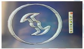
Star Grain Configuration:
Onedesignforsolidrocketpropellantgrainisthestargrain,whichischaracterizedbynumerousperforationsorchannels inside the grain that form a star shape. By manipulating the size, shape, and orientation of the channels in star grains, designers have the ability to alter the burn rate. Typical star grains have a central core with numerous radial channels or perforations radiating outward, giving them a star-like or asterisk-like cross-sectional structure. The pattern formed by these channels is reminiscent of a star's points. Its neutral burning properties make it the most widely utilized.

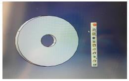
Circular Grain Configuration
A few solid rocket motors have a particular design that involves a circular grain geometry configuration. Circular grains, in contrast to star grains, which feature radial channels, have a more homogeneous and simple cross-sectional shape, looking like a disk or cylinder [6]. Burning occurs more equally throughout the full surface of round grains.
Double Anchor Grain Configuration:
One particular grain shape utilized in solid rocket motors is the "double anchor" grain. The term "double anchor" is used to describe this design because it has two separate perforations or channels in the solid propellant grain that are symmetrical and shaped like an anchor [2]. With regard to its central axis, the grain exhibits symmetry. A balanced and symmetrical burning pattern is created by its two similar channels, which are often positioned opposite one other.
www.ijprems.com
editor@ijprems.com
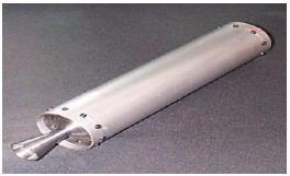
Casing
AND SCIENCE (IJPREMS) (Int Peer Reviewed Journal)
Vol. 04, Issue 11, November 2024, pp : 1593-1605
The combustion process occurs within a housing called a combustion chamber. This housing is designed to endure the extreme heat and pressure that are produced when the solid propellant is ignited. Metals such as titanium, aluminum, austenitic stainless steel, and T0T6. These materials can withstand temperatures of at least 650 degrees Celsius with ease (18)
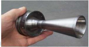
Nozzle:
Nozzles are tubes with variable (and often asymmetrical) cross-sectional areas used to alter the shape and velocity of an outflow. There are two distinct kinds of nozzles: convergent and diverging. As they make their way towards the nozzle, the gases undergo a process that changes their chemical energy into kinetic energy. The gases are expelled at high speeds via the nozzle.
Propellant:
Propellants are chemical mixtures that, when ignited, burn at a high rate. Propellant primarily consists of fuel and an oxidizer. In order to burn fuel, an oxidizer is used. Varying the proportions of these two factors affect how quickly propellant burns. Fuel and oxidizer are combined to form the propellant that solid rocket motors use. The usual ingredients are powdered oxidizers like ammonium perchlorate and powdered metals like aluminum.
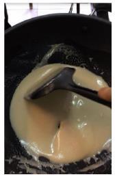
Rocket Candy
An informal way of referring to "sugar propellant" or "sugar rocket propellant" is "rocket candy," which is a form of homemade or amateur rocket propellant. Because of its shape and texture, it is commonly referred to as "candy" [3]. The fuel for rocket candies is usually a combination of powdered sugar (sucrose) and an oxidizer (KNO3), the most prevalent of which is potassium nitrate.
www.ijprems.com
editor@ijprems.com
(Int Peer Reviewed Journal)
Vol. 04, Issue 11, November 2024, pp : 1593-1605
2. LITERATURE REVIEW
(Dong-Hui, 228AD) Grain designs that adhere to traditional methods typically include human intervention in order to determine the optimal geometrical parameters to enhance grain performance and fulfill flight mission specifications. To optimize the design of propellant grains for solid rocket motors, this paper presents an integrated architecture.
(Yücel, 2015) Finding the grain geometry parameters that maximize the total impulse parameter while satisfying the limitations of chamber pressure and propellant mass and an objective thrust versus time profile are two examples of optimization issues that these methods are used to.
(Kumar, 2014) During the design phase, the intricate configuration is defined by dynamic variables, which are used in CATIA software for parametric modeling of the geometry.
(Püskülcü, 2004) The grain geometry's burn area change can be derived from the analysis of these geometries. The solid propellant rocket motor's performance is attained with the use of this data and internal ballistics characteristics. Rocket motor tests are conducted to confirm the results of this investigation.
(Hojat Ghassemi, 2002) The motors made from a combination of these three primary grains have very distinct interior structures. All tests utilized a propellant that was 81% solids composite and based on polyurethane.
(YILDIRIM, 2005) By assuming constant pressure along the motor, this study analyzes and predicts pressure time histories for some of the more traditional two- or three-dimensional grain burnbacks. An experimental static hybrid rocket test bench developed for this study was used to conduct the characterisation experiments.
(Horowitz, 2008) The grain design influences the insulating mass and volumetric loading, which are represented by the following parameters: web percent, thrust profile, and length-to-diameter ratio.
(Hejl, 1995) Not only is this tool easy to use, but it also has generic capabilities for managing burning rate information that is dependent on space.
(Kamran, 2009) To determine how manufacturing differences affect the optimal solution's sensitivity to uncertainties in design parameters, a Monte Carlo sensitivity analysis was performed.
(Michael A. WillcoX, 2007) Reliable internal ballistics predictions with appropriate simplified flowfield models can be achieved with sufficiently accurate models ofdynamicburning and erosive burning,according to theresults. This allows for significant reductions in computation time compared to 3-D, multiphase reacting flow simulations.
(A and A. Ulas b ET.AL, 2008) Tests using subscale ballistic rocket motors were carried out in this study to confirm the model's predictions. Modifications were made to an existing rocket motor to improve its insulation, ignition delay, and sealing.
(K Obula Reddy, 2013) During the design process, the intricate arrangement is defined by dynamic variables in computer-aided design (CAD) software, which allows for parametric modeling of the geometry.
(D. Scott Stewart, 2007) The results show that for time scales of the complete motor burn, this method provides sufficient accuracy with reasonable computation time. The final code, Rocgrain, integrates with existing internal flow codes and enables motor grain design with commercially available, user-friendly CAD applications.
(Lorenzo Casalino∗, 2011) The results demonstrate that tiny launchers could benefit from a hybrid-propellant third stage, which offers comparable cost and performance to an all-solid rocket. It turns out that using quadrangular ports is better than using triangle ports.
A very good match is achieved with static test results, and the code is validated with both published experimental findings and data for solid rocket motors of tactical and strategic missiles. Code output includes pressure-time (p-t) curve, axial flow parameters, and mesh files with geometries that can be used as input to computational fluid dynamics (CFD) programs.
(Ulas, 2008) The grain geometry's burn area change was derived from the analysis of various geometries. The solid propellant rocket motor's performance was attained in terms of motor pressure using this data in conjunction with internal ballistic parameters.
In other words, some star-aft motors can have their initial pressure spike effectively prolonged through erosive burning.
(Urrego Peña, 2019) Reliable internal ballistics predictions with appropriate simplified flowfield models can be achieved with sufficiently accurate models ofdynamicburning and erosive burning,according to theresults. This allows for significant reductions in computation time compared to 3-D, multiphase reacting flow simulations.
(Kumar,2014) ParametricmodelingofthegeometryinCATIAsoftwareisused todefinethecomplicated configuration through dynamic variables during the design process. A surface defining the grain configuration defines the initial geometry.
www.ijprems.com editor@ijprems.com
AND SCIENCE (IJPREMS) (Int Peer Reviewed Journal)
Vol. 04, Issue 11, November 2024, pp : 1593-1605
Impact Factor : 7.001
(Mohammed Akbar, 2024) This study delves into the topic of optimizing combustion chamber surface area and propellant volume through the use of finite element analysis and the differential calculus approach.
(Ionel, 2020) Each geometrical parameter that defines the star port SRM grain section is shown to be important in the results.
(Zafer Dursunkaya, 2015)Using optimization techniques, we maximize the total impulse parameter while keeping chamber pressure and propellant mass as constraints, and we determine the grain geometry parameters that fulfill an objective thrust versus time profile.
(Stalin, 2020) To determine the interior ballistics, the equilibrium pressure approach is employed. When it comes to preliminary grain configuration design, the selected approach is simple enough to be applied to any complicated geometry.
3. METHODOLOGY
Experimental Details:
Designing the propellant grain to enable the necessary change in thrust vs. time for the rocket mission's fulfillment is the major purpose, while other specific limitations such as envelope and mass are taken into account. Two tiers of solid propellant rocket motor analysis are now underway, with each tier requiring evaluation of the following four fundamental processes.
• Assessment of several types of propellant types/configurations,
• Defining the geometry of propellant grain which satisfies conditions of internal ballistics and structural integrity,
• Approximate determination of erosive burning and potential instability of burning process,
• Determination of structural integrity of the grain during time of pressure increase during ignition.
Preliminary or first-level design analysis requires tools that are both user-friendly and straightforward. In most cases, basic computer programs are available, which provide basic initial results based on analytical models or diagrams. The finaldesignof thepropellantchargeiscompleted onthesecondstage.Propellantgraindesignspecialistsusespecialized, high-tech equipment for this work. Internal ballistics, fluid dynamics, continuum mechanics, and structural analysis are some of the physical processes modelled in 1D, 2D, or 3D computer programs. These models are based on finite difference or finite element approaches. They enable optimization or exact computations all the way to the definition of final geometry.
It is crucial to perform laboratory testing on all components before manufacturing the final product. This ensures that the rocket engine meets all internal ballistic requirements and determines the burning law of the propellant, including erosive burning. The pressure time curve is the primary result of the experiment, which involves a rocket motor that is lying on a horizontal test stand and composite propellant. By attaching a pressure transducer to the rocket motor under test, we may examine its internal ballistics using the pressure time curve. During the erosive burning variables, this experiment will include erosive burning. (Pressure, burning rate, cross flow velocity, motor size, etc.), where L/D is a significant determinant in erosive burning [16].
Data from computer-aided design (CAD) and mathematical programming (MATLAB) programs will be compared with experimental results.
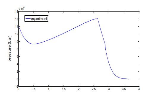
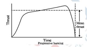
Fig. 7. Pressure time curve due to experimental data.
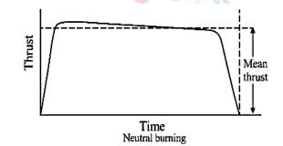
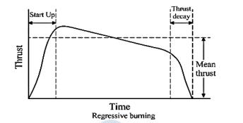
The pressure time curve reveals that the igniter and erosive burning cause a pick at the start of burning. The first burn area, which is affected by grain form and flow velocity, determines the pressure inside the rocket motor. As the first stage of the star grain geometry burns, the pressure drops sharply; as the second stage burns, the pressure rises again; hence, the burning is progressive. Once the burning phase is complete, the silver phase will begin to burn. Here the pressure begins to drop and the burning area shrinks rapidly as well.
www.ijprems.com
editor@ijprems.com
AND
(IJPREMS) (Int Peer Reviewed Journal)
Vol. 04, Issue 11, November 2024, pp : 1593-1605
4. PERFORMANCE PREDICTION
Using the equations of mass conversation, ideal gas formulation, and ideal gas velocity, the simplified ballistic model is used to calculate the performance prediction. The pressure time curve shows the rapid change of pressure inside the rocket motor during burning [19].
By inputting the propellant's thermochemical parameters, nozzle diameters, and performance efficiencies into a coding program, the pressure and thrust time curves may be calculated.
A. MATLAB simulation
The software can plot a pressure time curve and determine the star grain's performance. In order to determine the primary characteristics and performance of a solid propellant rocket engine, the program use SI units for computation.Rocketsofallsizesarewelcometoutilizetheprogram.TheP-Tcurveanderosiveburningphenomena calculations are the program's primary functions. In order to easily calculate and determine the output with little mistake, we shall divide the web thickness into equal segments By modeling the flow through the nozzle as isentropic and applying the theory of zero-dimensional frictionless compressible flow, the internal ballistic analysis is able to determine the proper chamber pressure that balances the continuity equation through iteratively establishing equilibrium pressures. The web thickness is divided into segments. The governing equation is solved for each segment, and the total mass generated is compared to the mass discharge through the nozzle. If the check fails, a new assumption is needed to obtain a solution for one instant in time. Liner between the head and nozzle end is considered the average burning rate. Along the combustion path, we presume a linear relationship between the burning rate and pressure at the head and nozzle ends.
B. Numerical Solution Procedure
Assuming all parameters are known at each increment of burning, the following methods are used to predict the pressure variation with time:
1. For this phase, we iteratively find the Mach number (mn) at the nozzle end (mn = 0.6), and we accept the result when the difference between two subsequent values drops below 0.00000001.
2. Determine the end-of-nozzle gas velocity (Un) in the chamber.
3. Sections are formed by dividing the web thickness.
4. Foretell the mass discharge rate and stagnation pressure.
5. Find the head pressure and the nozzle burning rate (ph, rh, pn, rn) separately.
6. Lenoir and Robillard's equation estimates the overall burning rate, which includes the erosive burning term, therefore we may determine the total burning rate. Using the Newton-Raphson approach, we are able to calculate the equation for the burning rate at the nozzle end. When the difference between two consecutive values drops below 0.000001, the answer is considered approved.
7. Get the mas flow rate and dp/dy.
8. Since the mass discharge and the mass created are not equal, we need to determine the new stagnation pressure. After that, keep going through steps 3–7 until the difference between two consecutive mass figures is somewhere around 1%.
9. Find out how long the whole burning rate takes at this point.
10. When the web thickness from the nozzle side reaches the motor casing, repeat steps 1 through 8.
The model takes into account the conservation of mass, energy, and momentum, and is based on the fundamental gas dynamic and thermodynamic relationships. The majority of rocket motors undergo a three-stage evaluation of their pressure time histories: ignition, transient, quasi steady, and tail off transient. Each stage is treated independently. Through iteratively establishing equilibrium pressures, the internal ballistic analysis determines the proper chamber pressure that balances the continuity equation. This is done in accordance with the one-dimensional frictionless compressible flow theory, which assumes that the flow is isentropic in the nozzle.
The solution of the governing equations for each segment can be obtained by splitting the web thickness into segments. If the check fails, a new assumption is needed to acquire the answer for one instant of time, and the total quantity of mass generated will be compared with the mass discharge from the nozzle. The calculation is carried out in two parts: at the grain's head and nozzle ends.
It helps determine the gas velocity, temperature, and pressure at the grain's nozzle tip. The output is determined with minimum error by dividing theweb thickness into equal parts. Assuming a linear relationship between the Mach number and the pressure and burning rate at the head and nozzle ends along the combustion path:
www.ijprems.com
editor@ijprems.com
IN
MANAGEMENT AND SCIENCE (IJPREMS) (Int Peer Reviewed Journal)
Vol. 04, Issue 11, November 2024, pp : 1593-1605
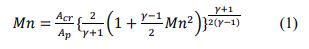
Where Mn is the Mach Number, Acr is the critical area, Ap is the port area, y is the specific heat ratio.
Impact Factor : 7.001
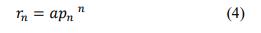
where the stagnation pressure (pon), burning rate coefficient (a), and propellant density (Pp) are all variables C is a function of the specific heat ratio, n is the combustion index, and is the characteristic velocity. The burning area is represented by Ab.
Where pn is pressure at the nozzle
www.ijprems.com
editor@ijprems.com
AND SCIENCE (IJPREMS) (Int Peer Reviewed Journal)
Vol. 04, Issue 11, November 2024, pp : 1593-1605
Impact Factor : 7.001
When we look at the presented curve alongside the theoretical and experimental data, we can see that there isn't much of a discrepancy. This indicates that the program can investigate the pressure time curve with little error and solve the internal ballistic of 2D star grains with different geometries. The theoretical calculation makes use of the phenomenon of erosive burning. The initial model to be developed based on heat transport was that of Lenoir and Robillard [20]. Two methods of gas-to-solid heat transfer were suggested in their mathematical model for predicting the consequences of erosive burning in solid propellant rocket motors:
1-from the main burning zone, where pressure is the only variable and core gas velocity is irrelevant 2-this method of calculating the entire burning rate (which is dependent on the gas velocity) from the hot combustion gases at the core is:
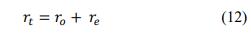
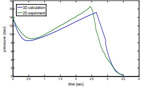
Fig. 9. Comparison of 2D experiment and 3D calculation.
Using 3D grain results in a decrease in pressure owing to a shift in the burning area, which improves performance inside the combustion chamber, as shown by the relation between the experimental 2D and theoretical 3D star grain curves above.
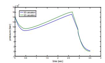
Fig. 10. 2D and 3D calculated pressure time curve.
Erosive burning causes a rapid transformation of any two-dimensional model into a three-dimensional one by increasing the burning rate at the grain end relative to its head. Therefore, we recommend using a 3D model since it allows for more precise burn back analysis of the grain, which in turn leads to more precise pressure estimation along the combustion chamber, whereas using a 2D model only yields inaccurate results (at least at the outset).
www.ijprems.com
editor@ijprems.com
AND SCIENCE (IJPREMS)
(Int Peer Reviewed Journal)
Vol. 04, Issue 11, November 2024, pp : 1593-1605
Theoretical Analysis
Impact Factor : 7.001
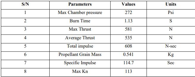
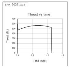
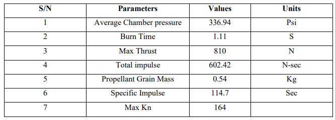
Richard Nakka's solid rocket motor (SRM) design Excel sheet is used for the study, whichhelps to analyze nozzle shape, thrust, pressure, and temperature.
Furthermore, a secondary confirmation is provided by an open motor configuration, which enables the entire experimental procedure to be run in a variety of environments. After that, the ideal range is chosen and confirmed. The parameters that indicate the outcome of the design, as shown in Table I, are,
Table :1 Result Parameters From Srm Excel Sheet
www.ijprems.com
editor@ijprems.com
AND SCIENCE (IJPREMS) (Int Peer Reviewed Journal)
Vol. 04, Issue 11, November 2024, pp : 1593-1605
TABLE 2: Result Parameters From Open Rocket
Impact Factor : 7.001
Ongoing analysis identifies the optimal range for this dimension, and we assess our specified burn profile characteristics. Based on this analysis, the thermal insulation layer is selected accordingly.
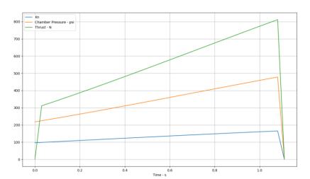
Fig. 15 Open Motor Simulation
This data gives a brief of how the motor is going to perform both data from both simulations are not exactly correct enough but its close enough in case of burn time and specific impulse, total impulse.
3.2 Combustion Chamber – CPVC
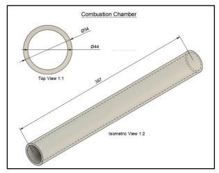
A 5 mm thick CPVC material is used to construct the combustion chamber, which includes a 367 mm schedule 40 SDR 11 pipe. Its starting operating pressure is 70 bars, and it is designed to operate under typical temperature circumstances. In our particular case, the temperature increases quickly a few seconds into the burn because the motor is built for a 4second burn, yet for some reason the CPVC can withstand high temperatures. Consequently, once the insulator has burned away, the inner wall will experience increased temperatures. Throughout this stage, the pressure inside the chamber is kept at 350 psi.
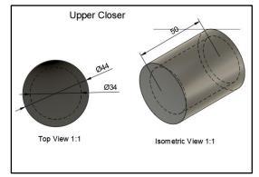
3.3 Upper Closer CPVC
www.ijprems.com
editor@ijprems.com
IN
AND SCIENCE (IJPREMS) (Int Peer Reviewed Journal)
Vol. 04, Issue 11, November 2024, pp : 1593-1605
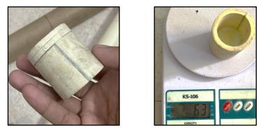
Fig.18 Upper Closer in Physical and Weighted
Step one is to mark the perimeter you want to cut, then use a hose clamp to secure the cut. After that, it's boiled for 5 minutes to further secure the assembly, and then the process is repeated until both joints are securely fastened. The next step is to use 743 quick glues and PVC powder to attach the sides. The combustion chamber's diameter is the basis for the bottom side's construction from flattened CPVC. Pouring Araldite epoxy adhesive from above strengthens the structure and stops leaks.
Assembling
Screwing in the nozzle and applying CPVC glue are the first steps in integrating the motor. After inserting the insulator and fuel grains, the top closure is attached with CPVC glue, screwed in, and then the fuel grains are entered.
5. RESULT & DISCUSION
An SD card is used to save the data received from the motor's static test, which is conducted on a horizontal static test pad.
TABLE 3 : Result From Static Test
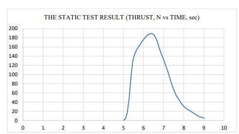
Fig:19 GRAPH I Static Test Result (Thrust, N vs Time, Sec)
The differences between the theoretical and real results are clear, and they are mostly caused by combustion loss, nozzle erosion, and mistakes made in the static test pad. With an average thrust of 102 N, the burn time has been increased from 1.1 seconds to 4 seconds. Along with a drop in combustion efficiency to0.7, total impulse is also reduced. Notwithstanding these discrepancies, the data yields highly congruent numbers. There is a drop in chamber pressure because the nozzle is greatly eroded by the increased mass flow rate. More intense combustion occurs in the top part of the convergence zone inside the combustion chamber.
www.ijprems.com editor@ijprems.com
6. CONCLUSION
AND SCIENCE (IJPREMS) (Int Peer Reviewed Journal)
Vol. 04, Issue 11, November 2024, pp : 1593-1605
Impact Factor : 7.001
An essential part of designing and calculating a solid rocket motor is doing a grain burn back study. Several experimental methods can be used to compare the results and data obtained from this work, which is based on our simple three-dimensional burn back analysis method. In order to confirm the theoretical answer, the MATLAB software compares the experimental results with the 2D star grain geometry's pressure time curve. Because of the assumptions made in the theoretical answer for simplicity computation, the discrepancy is tolerable. The burn back analysis and the area burning in both 2D and 3D star grain geometries are investigated using CAD drawings. In the course of the theoretical procedure, the erosive burning happens. As the pressure inside the combustion chamber lowers during burning, the 3D model's performance improves with respect to the pressure time curve. If you want to estimate the pressure along the combustion chamber with less room for error, a 3D model is your best bet for burn back study of the grain. Different 2D and 3D star grain geometries can have their pressure time curves and internal ballistics computed and studied using this MATLAB software. The rate at which a propellant burns depends on the grain shape, which is something we are aware of. Variations in grain size also influence the rocket's thrust and burn rate. A solid rocket motor's star grain design yields the optimal burn rate and thrust vs time graph with neutral burning when tested with different grain cross sections.
7. REFERENCES
[1] A, G.P. and A. Ulas b ET.AL (2008) ‘3-D grain burnback analysis of solid propellant rocket motors: Part 1 –ballisticmotor tests’, scence direct, 12(2008). Available at: https://www.sciencedirect.com/science/article/abs/pii/S1270963808000266.
[2] D. Scott Stewart (2007) ‘Solid Propellant Grain Design and Burnback Simulation Using a Minimum Distance Function’, JOURNAL OF PROPULSION AND POWER, 23(2). Available at: https://scihub.st/https://doi.org/10.2514/1.22937.
[3] Dong-Hui,W.(228AD)‘Anintegratedframeworkforsolidrocketmotorgraindesignoptimization’,Sagejornals, 7. Available at: https://journals.sagepub.com/doi/abs/10.1177/0954410013486589.
[4] Hejl, R.J. (1995) ‘Solid Rocket Motor Grain Burnback Analysis Using Adaptive Grids’, JOURNAL OF PROPULSION AND POWER, 11(05). Available at: https://sci-hub.st/https://doi.org/10.2514/3.23930.
[5] HojatGhassemi(2002)‘EffectsofGrainGeometryonPulse-TriggeredCombustionInstabilityinRocketMotors’, JOURNAL OF PROPULSION AND POWER, 18(1). Available at: https://scihub.st/https://doi.org/10.2514/2.5906.
[6] Horowitz, D. (2008) ‘OPTIMIZATION OF GRAIN AND STRUCTURE DESIGN OF A SOLID ROCKET MOTOR’, International Journal of Energetic Materials and Chemical Propulsion, 07(05). Available at: https://www.dl.begellhouse.com/journals/17bbb47e377ce023,6b0442161c2f317b,50ffc1793be1f6ad.html.
[7] Ionel, A. (2020) ‘Solid Rocket Motor Star Grian Geometrical Analysis And Performance Model’, RESEARCH GATE [Preprint]. Available at: https://www.researchgate.net/publication/347331196_Solid_Rocket_Motor_Star_Grian_Geometrical_Analysis_ And_Performance_Model.
[8] KObulaReddy(2013)‘BurnbackAnalysisof3-DStarGrainSolidPropellant’,InternationalJournalofAdvanced Trends in Computer Science and Engineering, 2(1). Available at: https://citeseerx.ist.psu.edu/document?repid=rep1&typepdf&doi=daef2e46791ed75fad357816eadbc552a6bcaf5
[9] Kamran, A. (2009) ‘Design and Performance Optimization of Finocyl Grain’, 10(13). Available at: https://scihub.st/https://doi.org/10.2514/6.2009-6234.
[10] Kumar,Y.N.V.S.(2014)‘DesignandGeometricalAnalysisofPropellantGrainConfigurationsofaSolidRocket Motor’,IJEDR,12(14).Availableat:https://rjwave.org/ijedr/viewpaperforall.php?paper=IJEDR1404010.
[11] Lorenzo Casalino∗ (2011) ‘Hybrid Rocket Upper Stage Optimization: Effects of Grain Geometry’. Available at: https://sci-hub.st/https://doi.org/10.2514/6.2011-6024.
[12] Michael A. WillcoX (2007) ‘Solid Rocket Motor Internal Ballistics Simulation Using Three-Dimensional Grain Burnback’, JOURNAL OF PROPULSION AND POWER, 23(3). Available at: https://scihub.st/https://doi.org/10.2514/1.22971.
[13] Mohammed Akbar (2024) ‘Design and Analysis of Optimized Solid Propellant Grain’. Available at: https://link.springer.com/chapter/10.1007/978-981-99-7827-4_58.
[14] Püskülcü,G.(2004)‘Analysisof3-d grain burnback of solid propellant rocket motors and verification with rocket motortests’,ODTU[Preprint].Availableat:https://open.metu.edu.tr/handle/11511/14570.
[15] Stalin,P.(2020)‘DesignandGeometricalAnalysisofPropellantGrainConfigurationsofaSolidRocketMotor’, RESEARCH GATE [Preprint]. Available at:
www.ijprems.com editor@ijprems.com
INTERNATIONAL JOURNAL OF PROGRESSIVE RESEARCH IN ENGINEERING MANAGEMENT AND SCIENCE (IJPREMS) (Int Peer Reviewed Journal)
Vol. 04, Issue 11, November 2024, pp : 1593-1605
Impact Factor : 7.001
https://www.researchgate.net/publication/346790447_Design_and_Geometrical_Analysis_of_Propellant_Grain_ Configurations_of_a_Solid_Rocket_Motor.
[16] Ulas,A.(2008)‘3-Dgrainburnbackanalysisofsolidpropellantrocketmotors:Part2 –modelingandsimulations’, 12(08). Available at: https://www.sciencedirect.com/science/article/abs/pii/S1270963808000199.
[17] Urrego Peña (2019) ‘Research in experimental rocketry : study of influence of geometric and manufacture parameters in combustion of polymeric hybrid rocket fuel grains’. Available at: https://repositorio.uniandes.edu.co/entities/publication/1f026728-c519-49ae-8bfb-6c7bb3282793.
[18] YILDIRIM, C. (2005) ‘NUMERICAL SIMULATION OF THE GRAIN BURNBACK IN SOLID PROPELLANTROCKETMOTOR’,10(13).Availableat:https://sci-hub.st/https://doi.org/10.2514/6.2005-4160.
[19] Yücel, O. (2015) ‘Three-dimensional grain design optimization of solid rocket motors’, IEEE xplorelore [Preprint]. Available at: https://ieeexplore.ieee.org/abstract/document/7208391.
[20] Zafer Dursunkaya (2015) ‘Three-dimensional grain design optimization of solid rocket motors’, IEEE xplore [Preprint]. Available at: https://ieeexplore.ieee.org/document/7208391.