16 minute read
All About Vacuum


The Science of Vacuum-Cup Forces
By Dane Spivak, Engineering Manager, Davasol Inc.
»FORCE GENERATED BY vacuum is not an alien concept. It is something we experience throughout our lives, whether it is putting a hand over a vacuum cleaner nozzle or drinking from a straw. We observe it regularly. But how can we break it down to understand, measure, and predict its affects? This article dives into exactly what vacuum is and how it generates force for vacuum cups to grip a surface.
Vacuum can be defined on earth as a pressure lower than atmospheric pressure in a known volume, atmospheric pressure being the datum point of measurement. The most common vacuum unit of measure used in North America is inches of mercury (inHg), but for the sake of this exercise we’ll use psi because it is more familiar in fluid power. Standard atmospheric pressure at sea level is 14.7 psi. This pressure is created by the weight of the air around us, which can change depending on the altitude and weather. To create a vacuum, a pressure lower than the atmospheric must be generated to establish a differential.
Figure 1 shows a 2-inch diameter, or 1-inch radius, vacuum cup connected to a tube placed on a glass surface. This is our known volume. If you attach a vacuum pump to the tube that generates a 60% vacuum, reducing the pressure inside the cup, the pressure inside the cup decreases to 5.9 psi, and therefore the differential from atmospheric pressure results in 8.8 psi. This 8.8 psi differential pressure – the difference between the pressure inside the cup and the atmospheric pressure outside the cup – is what we use to calculate the holding/gripping force of the vacuum cup. Force is the result of pressure multiplied by area. In the following example, the area is the circular 2-inch diameter vacuum cup, and the vacuum pressure is the differential pressure. The calculations show the holding force in pounds that the vacuum cup exerts coupled to the vacuum source. Area = πr2 = π×12 = 3.14 in2 Force (F1 ) = Pressure x Area = 8.8lbs/in2 × 3.14in2 = 27lbs
From a physical perspective, the atmospheric air pressure under the glass is pushing the glass up against the cup because there is a lower pressure inside. Therefore, vacuum force is limited by the available atmospheric pressure. If the atmospheric pressure is less, such as an area at altitude, then the applied force to the glass would be lower if the pressure inside the cup remained the same. The take away is that vacuum force from a suction cup is dependant on atmospheric pressure, vacuum-generated pressure inside the cup (vacuum level), and the area of the cup where vacuum is applied to the surface.
Figure 2 shows three 2-inch cups gripping a part, with two of them at a 40° angle. In this example, the cups intend to move directly upward when gripping the part. As we learned from figure 1, we can calculate the lifting force of the middle cup. However, the two outer cups are angled, which affects the amount of vacuum force being applied vertically. Sticking to our differential vacuum pressure of 8.8 psi, we know that the full area of a 2-inch cup applies a force of 27 lbs. But the angled cups apply less vertical lifting force as indicated by the vector arrows in figure 2. The calculations show the affects:
F1 = 27lbs F2 = F1×cosθ = 27×cos(40) = 21lbs F3 = F1×cosθ = 27×cos(40) = 21lbs Total Vertical Gripping Force = F1+F2+F3 = 27+21+21 = 69lbs
Now consider a full-shear application in which a cup is gripping a part at a 90° angle. From the calculations of figure 2, the angle would go to 90° and therefore zero the force from those cups. But intuition tells us that in a real-life situation, the part could still provide a vertical lifting force because figure 2 ignores the frictional force between the cups and the surface.
In figure 3, the same 8.8 psi and 2-inch cup generates a vacuum gripping force of 27 lbs. The amount of friction force is based on two factors. One is the vacuum gripping force, which applies a force that is 90° to the friction surface. This is typically referred to as the “normal force” when describing friction. Secondly, the coefficient of friction, known as Mu (µ), defines the percentage of the normal force exerted as friction. Coefficients of friction depend on the interaction of the cup with the product surface and how well or poorly they create friction. For example, a rubber cup on a smooth glass surface has a high coefficient of friction, whereas an oily metal sheet has a lower value as it is more likely to slip. The µ value can be found experimentally, though typical shear-gripping applications implement additional safety factors instead of calculating this value. The calculations
Figure 1 Figure 2 Figure 3
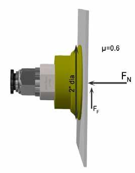
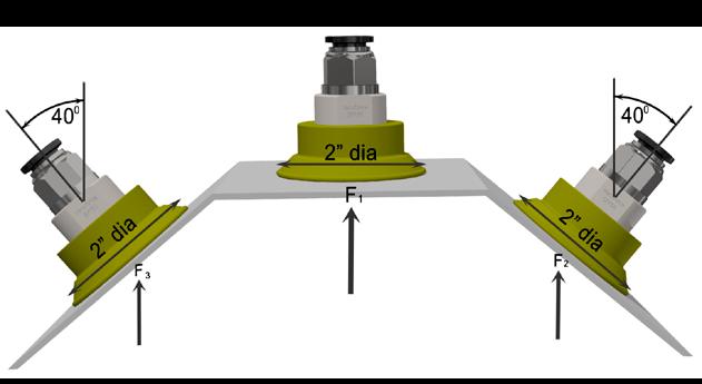
Figure 4

based on figure 3 demonstrate the frictional force. In this example, we chose the µ value arbitrarily and ignored weight and other external forces.
Normal Force (FN ) = 27lbs
Vertical Vacuum Force = FN×cosθ = 27×cos(90) = 0lbs μ = 0.6 Vertical Force = Friction Force (FF ) = FN×μ = 27×0.6 = 16lbs
As we see in the calculation from figure 3, the friction force delivers a significant impact to the applied forces of a vacuum cup. So the force created by the vacuum-level pressure and friction each contribute to the output.
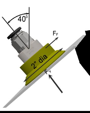
Figure 4 uses the same criteria as figure 3 but at an angle of 40°. This allows us to calculate the impact of both forces. Again, we’ve ignored weight and other external forces.
Vacuum Force = FV = 27lbs Vertical Vacuum Force = FV ×cosθ = 27×cos(40) = 21lbs Friction Force (FF ) = FV×µ Vertical Friction Force = FV×µ×cosθ = 27×0.6×cos(50) = 10lbs Total Vertical Force = 21+10 = 31lbs
Vacuum-cup forces are generated by vacuum pressure and friction, which can be calculated for theoretical numbers. However, based on the application and product being gripped, there are other underlying factors to consider, and the appropriate safety factors and designs should be implemented. This article showcases concepts only. Reach out to a professional for your application needs.
This article is the opinion of the author, Dane Spivak of Davasol Inc., an industrial brand management firm with many clients. One of Davasol’s clients, Vacuforce LLC, based in Indianapolis, partners with the author on this article. Contact Dane Spivak at dspivak@davasol.com.
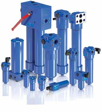
High Performance Filters
High Pressure Series
PASSION TO PERFORM
100% smart clean
For venting the electrical gear motors in a clean and reliable manner. Unique construction against moisture and dirt. Opening pressure 0.15 - 0.25 bar. 100% tested thanks to a fully automated assembly. Assembled transportation lock and dust cap possible.
HN LÜ-OR | VENT VALVE Our solution for reliable venting
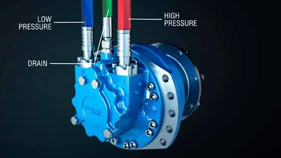
Cam Lobe Radial Piston Motors

Compact, Capable, Constant
By Franck Defer, Radial Product Marketing Manager, Poclain Hydraulics

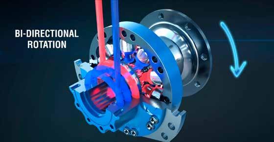
Cam lobe radial piston motors are low-speed high-torque motors. Fed by a pump, the motor rotates either clockwise or counterclockwise by a series of pistons that alternately receive oil under pressure to act on the cam profile. Given a constant input pressure, the cam profile is calculated to provide constant torque and speed, minimizing torque ripple and cogging. It is not a new technology, but it continues to evolve to fit a variety of needs for mobile equipment as well as tool drives and stationary industrial equipment (figure 1).
Radial piston motors can be used to provide the “direct drive” solution by supplying full torque without the need for high-speed motors connected through gearboxes. Having the radial piston motor connected directly to the work increases efficiency, making more power available at the shaft. Although high-speed motors and gearboxes have the reputation of being a lower-cost solution with simpler integration, there are a number of applications in which cam lobe radial piston technology is a better match to the machine’s requirements.
It is possible to attain the same level of power across a wide range of modular motors at different sizes, putting the technology in reach for different applications just by analyzing the machine’s specifications and determining the right modules to combine to address them. Identifying and specifying the max pressure, displacement, torque, speed, and power are the very base elements for motor selection. Beyond this, there are modular options to define depending on the machine specifications and hydraulic system architecture. Various bearing support types exist, such as wheel flange, splined shafts, shrink disk shafts, or sprocket shafts. The motors can also adapt to accommodate various types of chassis fixations with corresponding fixation geometries. Options include integrated brakes: parking, service, combined, caliper, and drum; flanged valves; and integrated pivots. Features that address temperature control, speed, reinforcement, and high-pressure connections open up possibilities for OEMs to integrate highly engineered solutions.
Advantages
Cam lobe radial piston motors are compact and fit in a smaller envelope. Their compactness has a
Figure 1 direct benefit for applications that require a lot of torque but have limited space in which to fit it – cutting heads for forestry equipment, harvesters, or sprayers, for example.
Imagine needing to pave a complex job, but when running the machine at the low speeds necessary to accomplish the work, the motor starts to cog and the quality of paving is less than desired. Highly precise movement and constant low speeds without that cogging effect are some of the main benefits of cam lobe radial piston technology. This is a need seen in the off-road and on-road arena – especially with road marking, high rail, or rail telehandler trucks. A creep function can be accomplished by integrating a hybrid mechanical-hydraulic transmission, allowing vehicles to work at low speeds without additional stress on braking and clutching, regardless of engine speed. This makes it possible for auxiliary systems to tap into the power they need to perform work effectively. An additional challenge with on-road vehicles is the need to drive at normal on-road speeds without mechanical losses.
The motor's high starting torque—available for the full speed range— and homokinetic design make precise and consistent rotation possible (figure 2). This, paired with an innate low inertia for smooth and easy direction changes, translates to better consistency in
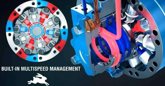
Figure 3 Figure 4

work quality for machines such as pavers and road-marking trucks on the construction side and reduced soil and ground damage on the agriculture side. The end benefit is a comfortable and productive end-user experience.
Safety is a real concern for everyone – agriculture, construction, rail and road, newer autonomous machines, and others. Beyond user comfort, the low inertia of this technology delivers an added safety benefit with instant stops and quick direction changes. This makes it easier for drivers to respond quickly to safety concerns (figure 3).
THE ULTIMATE CONTAMINATION CONTROL TOOL
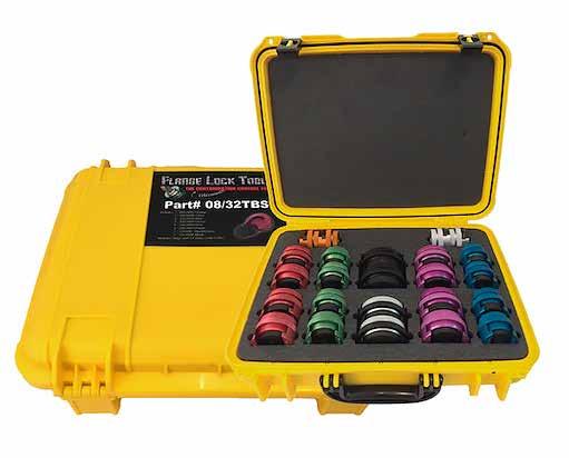
Cam lobe radial piston motors components into one. This reduces HITACHI FLANGELOCKTM In applications that seek to can be equipped with an internal valve that changes the displacefailure points and simplifies installation on complex architectures. increase uptime and reduce total cost of ownership, reduced AND CAP KITS AVAILABLE ment by deactivating some of the Reducing maintenance also affects unscheduled maintenance can pistons. This reduces torque and Part number total cost of ownership. Part description Applicable machines make a big difference. Innovative Number of parts Weight (kg) increases speed for a given flow SWINGFLGLCK2062 Swing hose FlangeLockTM kit EX3600, EX5600, EX8000 motor designs such as Poclain’s 16 x 2062U - red FlangeLockTM 6.7 and pressure. The valve responds Applications that benefitSWINGCAP2062 Swing circuit cap kit EX3600, EX5600, EX8000 MG steerable wheel motors with 16 x 2062 - cap 4.5 to a pressure signal and makes a When considering just the integrated pivot combine multiple smooth transition from one dis- core technology, anything that TRAVELFLGLCK2462 Travel hose FlangeLockTM kit EX3600, EX5600, EX8000 components to reduce possible 16 x 2462U - purple FlangeLockTM 7.7 placement to another (figure 4). needs high torque in a compact TRAVELCAP2462 Travel circuit cap kit EX3600, EX5600, EX8000 points of failure and eliminate the 16 x 2462 - cap 6.4 Cam lobe radial piston motors are built to go a lifetime with minpackage could benefit from cam lobe radial piston technology. FRONTATTFLGLCK326162 Front attachment FlangeLockTM kit EX3600, EX5600, EX8000 need to service gearboxes. These newer designs reduce fabrication 14 x 3262U - black FlangeLockTM 4 x 3261U - black & silver FlangeLockTM 8.9 imal regular maintenance. When Sprayers, grape harvesters, skid FRONTATTCAP326162 Front attachment cap kit EX3600, EX5600, EX8000 time and installation cost by elim14 x 3262 - cap 4 x 3261 - cap 9.5 choosing a modular cam lobe radial piston motor, it is possisteers, mini loaders, head cutters, crushers, and shredders – the BOOMARCHFLGLCK3262 Boom arch hose FlangeLockTM kit EX3600, EX5600, EX8000 inating the need to fabricate an axle, reducing the number of pieces 20 x 3262U - black FlangeLockTM 9.9 ble to reduce maintenance even applications span a wide number BOOMARCHCAP3262 Boom arch hose cap kit EX3600, EX5600, EX8000 that need to be installed. It also 20 x 3262 - cap 11.3 further by incorporating many of industries. CONTAMINATION CONTROL (Continued on page 24)
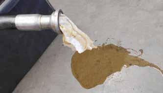
Routine and scheduled maintenance of hydraulic systems are vital to getting the most out of your Hitachi Mining Excavator. While maintenance plays the largest role in the prevention of unnecessary machine downtime, it can also expose the hydraulic system to high levels of contamination rapidly decreasing component longevity. The importance of contamination control is sometimes Stop the Mess overlooked when performing maintenance due to incorrect practices being used. THE FLANGELOCK™ TOOL AND CIRCUIT BLANKING CAPS The FlangeLock™ tool and caps are the ultimate contamination control tools for protecting your hydraulic system. The FlangeLock™ allows for the simple sealing of open hydraulic flanges without tools while the caps can be bolted in place of a flange connection. Easy on, easy off, they offer a leak-proof solution to hydraulic systems and environmental cleanliness. FlangeLock™ tools and caps stop the mess.
The FlangeLock™ Tool is the ultimate contamination control tool for protecting your hydraulic systems. It allows for the simple sealing of open SAE code 61, 62 HITACHI MAKING CONTAMINATION CONTROL EASY & CAT-Style hydraulic flanges without tools. Constructed from lightweight aluminum. Hitachi have packaged FlangeLock™ tool and caps specifically for Hitachi mining excavators. The Hitachi customised kits make sure no matter which component routine maintenance is being performed on, you will always have the exact Easy on, easy off. Offers a leakproof solution to hydraulic system and environmental number of FlangeLocks™* and caps to help reduce contamination. cleanliness. FlangeLock™ Tools stop the mess!*Note: FlangeLocks™ are not to be used under pressure
SAVE TIME SAVE MONEY SAVE LABOR SAVE OIL
This product is Patented, other Patents pending. • • • No tools required No expensive hardware needed No more rags stuffed into hoses • One hand installation • Eliminate hydraulic oil spills & clean up • Quick installation & ease of usage Call you local Hitachi Muswellbrook representative or the branch on 02 6541 6300 for more information. • No more messy plastic caps • Safe for personnel & environment • The ultimate contamination control tool • Industry acclaimed


For more information, call 203-861-9400 or email sales@flangelock.com. www.flangelock.com
Don’t compromise!

Use MAIN Manufacturing Products, Inc. as your source for hydraulic flanges
Dependable - 60 yrs service Informed - members of SAE, ISO, & NFPA tech committees
Quick - Thousands in stock specials can be 3-4 days
Made in USA
SAE J518, JIS, DIN, ISO, standard & special adapters Socket & Butt weld, NPTF, BSPT, ORB, BSPP, 6149, ETC. In-line, el, tee, F, blind, cross, cross, flanged, reducing, flange heads, couplings
Materials: Carbon, 304L, 316L, Duplex, Cu-NI, Ductile, Aluminum, etc.
Grand Blanc, MI USA
Mobile - Portable HII EXPERTS IN HIGH PRESSURE TESTING
HYDRAULICS or PNEUMATICSHydraulics International, Inc. MOBILE • PORTABLE
• Hydrostatic Pressure Testing • Bolt Tensioning & Nut Torquing • Chemical Injection • Charging of N2 Accumulators • Leak Testing • Fluid Measuring Systems • Clamping • Valve Actuation • Calibration • Gas Transfer • Coolant Injection
9201 Independence Ave., Chatsworth, CA 91311 USA (Phone) 818.407.3400 | (Fax) 818.407.3428 www.hiipumps.com
Made in the USA
(Continued from page 23) frees up space to streamline design and engine placement. Closer wheel centers and slimmer machines translate to a smaller turn radius and increased productivity for the customer. Reducing the steering radius increases productivity for agriculture machines, helping them to increase precision of work and the acres they are able to cover per hour. In the construction industry, the technology allows for better maneuverability in articulated machines such as miniloaders.
Tracked equipment presents a different set of challenges. It requires a perfectly balanced motor that withstands high axial and radial loads, delivers equal power in forward and reverse, has superior resistance to pollution, and can manage high ground speed without losing torque. Newer technology with high bearing capacity, reinforced seals, and symmetrical design meets these challenges.
Figure 5
Compatible technology
Mobile equipment markets continue to explore zero-emission technology. Hydraulic radial piston cam lobe motor transmissions combined with electropumps can help facilitate the switch from hydrostatic ICE-driven machines to zero-emission solutions. Part and chassis commonality between diesel and electrohydraulic machines can ease the transition and learning curve for the end user and maintenance crews while enabling OEMs to meet environmental and regulation pressure to produce lower or zero-emission machines.
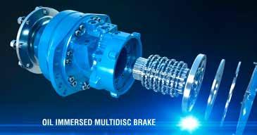
Another persistent trend is integrating more functionality into the motors, enabling OEMs to do more with one component. High-resolution sensors and integrated braking solutions such as parking, dynamic, or combined options augment the precision of the motor, making it possible for the technology to meet the stringent safety and precision requirements of autonomous vehicles. Oil-immersed integrated brakes make it possible for grape harvesters to meet even more challenging inclines. They allow sprayers to meet new roading regulations when using higher speeds to get from field to field, and they give mining vehicles the stopping power needed for steep inclines (figure 5).