28 minute read
Notable Words

Infuse Value Proposition into Your Company’s DNA
By Paul Johnson, President, Aggressive Hydraulics
»IN THIS DAY and age of Amazon and Omnichannel for retail, we are becoming conditioned to buy differently while getting the best pricing available. Beyond pricing, we want the experience to be easy. You don’t have to go to the store because delivery to your home is common, and in many cases the shipping is free. Department-store chains have built multimillion-square-foot fulfillment centers to support their online shopping platforms. If fast food is not convenient enough, you can have DoorDash deliver your meal for a modest fee. If you don’t have time to grocery shop, you can use Instacart.
How are these trends in retail affecting fluid power supply chains? Business dynamics are changing, and manufacturing suppliers, regardless of the industry, must change to adapt to customer demand for improved experience. Downward pricing pressure is always present. In some cases, the initiatives pursuant to managing a vendor’s products can tend to commoditize everything. By definition, a commodity is the market treating the good as equivalent or nearly so, with no regard to who produced it.
How do your customers view your company as part of their supply chain? Are you the supplier that provides the cheapest price? Are you viewed as a commodity? Hopefully you’re providing a value proposition that is aligned with what your customers need and want. A hydraulic component can be defined by category or class, but when your products are defined or viewed as a commodity, it is problematic. What about the company that produces it? This is when differentiation of the company and the product becomes imperative.
The company
Companies are challenged to create a value proposition that will continue to deliver products and services that meet customer expectations in an ever-changing landscape. Is your value proposition a reflection of your company or of your products and services? A value proposition is much like a warranty; it is only as good as the company that stands behind it. A good value proposition should not be aspirational; it should be something ingrained in the DNA of the company culture and every employee within the organization.
Aggressive Hydraulics has embraced the tools found in the Entrepreneurial Operating System (EOS) described in the book “Traction,” by Gino Wickman. EOS aligns our employees and focuses our efforts on the right things. For example, we have defined our Three Uniques that we believe set us apart from others in our industry. They are the heart of the value proposition our company offers to our customers. They are unchanged by customer situations, market trends, or the economic landscape. All employees know our Three Uniques, which are part of our culture.
The product or service
In addition to differentiating your company, it is also advantageous to differentiate your products or services. This has always been a challenge, but is even more important in our rapidly changing market, which is influenced by today’s retail trends and the social and economic impact of the pandemic. If your product is considered a commodity by the market, customers will consider price first when selecting a supplier. In contrast, a sales transaction based on value flows from collaborative discussions between supplier and customer regarding productivity, reliability, and durability. This can lead to breakthrough technology that radically changes the way work is done. It can also lead to multiple incremental changes with a greater aggregate impact than a single breakthrough technology. For the sustainability of your customer relationship, your product or service value needs to be evident and acknowledged before, during, and after the sale.
Upon inception, Aggressive Hydraulics made the conscious decision to not provide commodity products. Our hydraulic cylinders are built to order, operating on every continent, and are typically in applications supporting essential services and infrastructure. To ensure our products work as intended in demanding applications, we have a process that goes beyond custom, so we use the term purpose-built. A custom product can be a pre-engineered or predesigned product that is modified to fit an application in terms of fit, form, and function. But these products are not necessarily engineered and designed specifically for the intended application. When our sales, engineering, and manufacturing teams develop and manufacture a purpose-built product, we use another EOS tool called proven process. This is our method to consistently create successful purpose-built hydraulic cylinders for our customers, from initial gathering and understanding requirements to final delivery of the product and providing ongoing support.
Consider leveraging your internal processes, tools, and culture to provide differentiation and value selling, resulting in a positive experience for your customers and prospects. Never lose sight of your value proposition and stand behind it.
PUBLISHER Innovative Designs & Publishing, Inc. 3245 Freemansburg Avenue, Palmer, PA 18045-7118 Tel: 800-730-5904 or 610-923-0380 Fax: 610-923-0390 • Email: Art@FluidPowerJournal.com www.FluidPowerJournal.com
Founders: Paul and Lisa Prass Associate Publisher: Bob McKinney Editor: Michael Degan Technical Editor: Dan Helgerson, CFPAI/AJPP, CFPS, CFPECS, CFPSD, CFPMT, CFPCC - CFPSOS LLC Art Director: Quynh Fisher Eastern Region Acct Executive: Norma Abrunzo
Director of Creative Services: Erica Montes Accounting: Donna Bachman, Sarah Varano Circulation Manager: Andrea Karges

INTERNATIONAL FLUID POWER SOCIETY 1930 East Marlton Pike, Suite A-2, Cherry Hill, NJ 08003-2141 Tel: 856-489-8983 • Fax: 856-424-9248 Email: AskUs@ifps.org • Web: www.ifps.org
2021 BOARD OF DIRECTORS President: Rocky Phoenix, CFPMMH - Open Loop Energy, Inc.
Immediate Past President: Jeff Kenney, CFPMHM, CFPIHM, CFPMHT - Dover Hydraulics South First Vice President: Denis Poirier, Jr., CFPAI/AJPP, CFPHS, CFPIHM, CFPCC - Eaton Corporation Treasurer: Jeff Hodges, CFPAI/AJPP, CFPMHM - Altec Industries, Inc. Vice President Certification: James O’Halek, CFPAI/AJPP, CFPMIP, CMPMM - The Boeing Company
Vice President Marketing: Scott Sardina, PE, CFPAI, CFPHS Waterclock Engineering
Vice President Education: Randy Bobbitt, CFPAI, CFPHS Danfoss Power Solutions Vice President Membership: John Bibaeff, PE, CFPAI, CFPE, CFPS
DIRECTORS-AT-LARGE Chauntelle Baughman, CFPHS - OneHydraulics, Inc. Stephen Blazer, CFPE, CFPS, CFPMHM, CFPIHT, CFPMHT Altec Industries, Inc. Randy Bobbitt, CFPAI, CFPHS - Danfoss Power Solutions Steve Bogush, CFPAI/AJPP, CFPHS, CFPIHM - Poclain Hydraulics Cary Boozer, PE, CFPE - Motion Industries, Inc. Lisa DeBenedetto, CFPS - GS Global Resources Daniel Fernandes, CFPECS, CFPS - Sun Hydraulics Brandon Gustafson, PE, CFPE, CFPS, CFPIHT, CFPMHM - Graco, Inc. Garrett Hoisington, CFPAI/AJPP, CFPS, CFPMHM Open Loop Energy Brian Kenoyer, CFPHS - Five Landis Corp. Jon Rhodes, CFPAI, CFPS, CFPECS - CFC Industrial Training Mohaned Shahin, CFPS - Parker Hannifin Randy Smith, CFPHS - Northrop Grumman Corp.
EXECUTIVE DIRECTOR (EX-OFFICIO) Donna Pollander, ACA HONORARY DIRECTORS (EX-OFFICIO) Paul Prass, Fluid Power Journal Liz Rehfus, CFPE, CFPS Robert Sheaf, CFPAI/AJPP, CFC Industrial Training

IFPS STAFF Executive Director: Donna Pollander, ACA Communications Director: Adele Kayser Technical Director: Thomas Blansett, CFPS, CFPAI Assistant Director: Stephanie Coleman Certification Coordinator: Kyle Pollander Bookkeeper: Diane McMahon
Administrative Assistant: Beth Borodziuk
Fluid Power Journal (ISSN# 1073-7898) is the official publication of the International Fluid Power Society published monthly with four supplemental issues, including a Systems Integrator Directory, Off-Highway Suppliers Directory, Tech Directory, and Manufacturers Directory, by Innovative Designs & Publishing, Inc., 3245 Freemansburg Avenue, Palmer, PA 18045-7118. All Rights Reserved. Reproduction in whole or in part of any material in this publication is acceptable with credit. Publishers assume no liability for any information published. We reserve the right to accept or reject all advertising material and will not guarantee the return or safety of unsolicited art, photographs, or manuscripts.
3-PORT DIVERTER VALVE
Inserta® 3-Port Diverter Valves provide a simple means to install a diverter ball valve in a circuit that uses an SAE J518 4-Bolt mounting flange pattern. Compact assemblies can be made, and adjoining components are face sealed with a leak resistant O-ring.
The pressure containing flange body is traceable to manufacturing and material lot. A variety of lock plates are available.
INSERTA® PRODUCTS Blue Bell, PA 215.643.0192 www.inserta.com
© 2021 Inserta®
Hydraulic Contamination Solutions
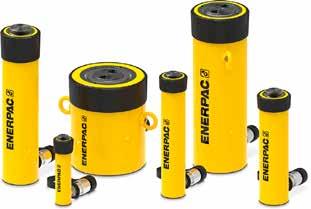
ICM 4.0 Inline Particle Counter
• Complete hydraulic health checks • Real-time contamination monitoring • Prevents unscheduled downtime • Protects machinery, enhances lifespans
LPA3 Portable Particle Counter


HAPPY FLUID POWER PROFESSIONALS’ DAY
June 19 is Fluid Power Professionals’ Day. The International Fluid Power Society designated Blaise Pascal's birthday as a day to honor all industry professionals. Past celebrations have included company picnics and barbecues, theme park outings, and pizza parties. We'll hopefully get back to those activities in 2022!
Thank you to all who’ve made the fluid power industry what it is!
CELEBRATING 60 YEARS
www.jasonindustrial.com 630.752.0600
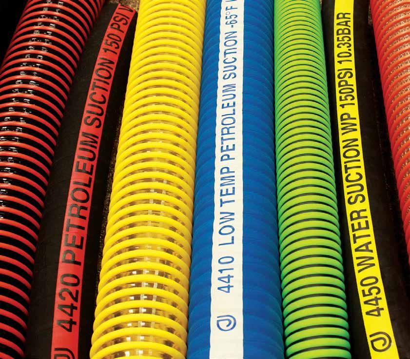
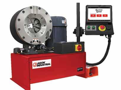
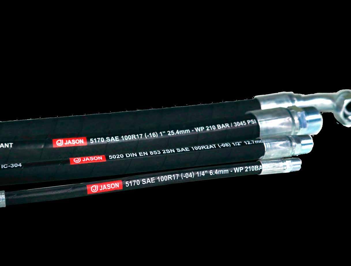
Industrial and Hydraulic Hose, Couplings, Equipment and Accessories where you need it, when you need it.
For the US, we have locations in Fairfield, NJ; Carol Stream, IL; Tampa, FL; Dallas, TX; Los Angeles, CA and Portland, OR.
Member of Ammega Group ammega.com
Reaching New
By Steve Weber, Engineering Team, Sun Hydraulics Heights IN LOAD HOLDING FOR CRANES
Efficient, effective load holding is not easy. But you can improve your results and achieve counterbalance in almost every application if you apply an informed counterbalance valve selection in a smart circuit design. Two case studies involving cranes demonstrate the necessity of good counterbalance valve selection and the importance of smart circuit design for the best performance and stability.
Case study 1 The Federated construction crane
A load-holding challenge began with the collapse of a crane at a New York City construction site. As a result of the collapse, city building inspectors changed their inspection process at active construction projects with cranes. It would now include looking for evidence that the counterbalance valve had been adjusted after leaving the factory, which would demonstrate to the inspector that the valve had been tuned to the application. If there was no obvious way to show that there was a post-factory setting, the load-holding valve had to be replaced.
The chief engineer at Federated Crane Company contacted Sun Hydraulics and asked what options Sun could offer to help meet this new requirement. During the discussion, the conversation expanded to include the real challenge – improving the performance of the winch on their cranes.
Federated Crane’s equipment mounts to the side of a building under construction and climbs the outside of the building as the skyscraper expands upward. A track is mounted on the building and a pony motor powers the hydraulic system that moves the crane up the side of the building. These cranes are used to deliver materials such as concrete and rebar to the floors under construction. As a result, the winch control has to account for a 1000foot payout of wire cable used to move materials up to the active floors.
Federated’s cranes had a Sun counterbalance valve installed on the winch circuit with a standard adjust screw. The engineer needed to replace the counterbalance valve with the standard adjust screw in the winch circuit with something that would satisfy the inspector’s requirement of a visible sign that the valve setting had been adjusted outside the factory. That was the easy part. The challenge was in his request to improve the performance of the winch.
The challenge. At that time, Federated Crane was working on the reconstruction of the World Trade Center, the tallest building in the U.S. and the sixth tallest in the world. As these cranes make their way up the building, that 1000-foot payout acts like a large spring-mass-damper system but with little dampening. In a winch circuit with a counterbalance, there is an inverse relationship of a lightly loaded hook needing higher system pressure to pay out. And with the long lengths of wire rope acting as a damper system, it makes stability particularly challenging.
Instability comes from the counterbalance valve being piloted too far open, which allows the actuator to overrun the pump, causing the system and pilot pressure to drop. As a result, the counterbalance valve suddenly closes. When system pressure and pilot pressure recover, the counterbalance valve reopens. This repeating cycle of opening and closing is often called chattering and can occur in both motor and cylinder applications. Chattering is a familiar sound to hydraulics engineers working on load-holding solutions.
In the Federated Crane application, smooth acceleration and deceleration of the load was critical. Without it, the long length of wire rope acted as a spring, allowing the winch motor to briefly overrun the pump, starting that cycle of instability and chatter. Performance of the winch was at times unstable and not smooth. The company’s chief engineer reported that when the hook was lightly loaded or had no load, stability was worse than when the hook was heavily loaded.
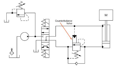
Figure 1 shows a typical open loop motor circuit in which the counterbalance valve acts as a brake for the motor driving the winch. The Federated Crane solution was a closed loop hydrostatic motor driving the winch. Therefore, heat generation was a prime consideration when deciding alternatives to improve performance. More heat could require more oil to be bled from the closed loop system for cooling. This might require a larger charge pump to replenish the hot oil that bleeds off for cooling.
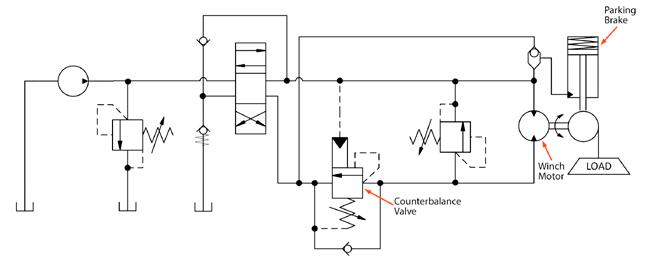
Figure 1
The solution. This is where an informed counterbalance valve selection makes a difference. Sun recommended a load-control style counterbalance valve because it is hydraulically dampened internally and offers superior control resolution. The control resolution is improved by offering low-flow and high-flow modulation in the same valve. Additionally, it is a poppet valve, providing extremely low leakage for use as a counterbalance valve. But once the poppet leaves its seat, it acts like a spool valve to improve control resolution.
Pilot line dampening with an orifice is commonly included in the control circuit, which can sometimes create issues for a winch motor. A simple orifice dampens the pilot flow into the valve to slow the valve opening, but it also decreases the flow of pilot oil from the valve. This can lead to the motor overrunning the pump and cavitating. With an open loop winch motor circuit, regaining control of load might not happen, at least not until the load hits the ground, which for almost all applications is too late.
A smarter circuit design includes an orifice with a bypass check. This valve dampens the pilot flow into the valve to slow the opening, and the check valve allows the pilot flow out unrestricted to allow the counterbalance valve to close and prevent an overrunning load. Additional dampening is sometimes possible internal to the valve, making use of a similar concept to further dampen the valve opening but not slow the valve closing.
For the Federated Crane application, we combined the Sun load-control counterbalance valve with the internal dampening and pilot orifice in the new circuit with a bypass check valve and installed the resulting solution on the Federated crane. The result significantly improved stability compared to the original counterbalance valve. The chief engineer noted that the winch worked better than it ever had.
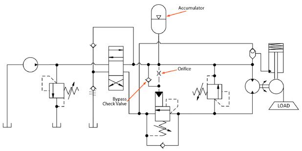
But why stop there? To further improve stability, a small accumulator was added to the pilot line. The schematic in figure 2 shows this modification on the typical open loop motor circuit. The small accumulator further smooths the pressure pulsations in the pilot resulting from the highly excitable spring-mass-damper created. The result of using an accumulator in the counterbalance pilot was, as one Sun engineer put it, “like a magic carpet ride.” After the final changes, the feedback from the Federated Crane operator was that the winch was stable in all conditions. Problem solved.
When performance matters
trust ACE with your toughest motion challenges
Extensive catalog of industrial shock absorbers, gas springs and hydraulic dampers
Online sizing tools
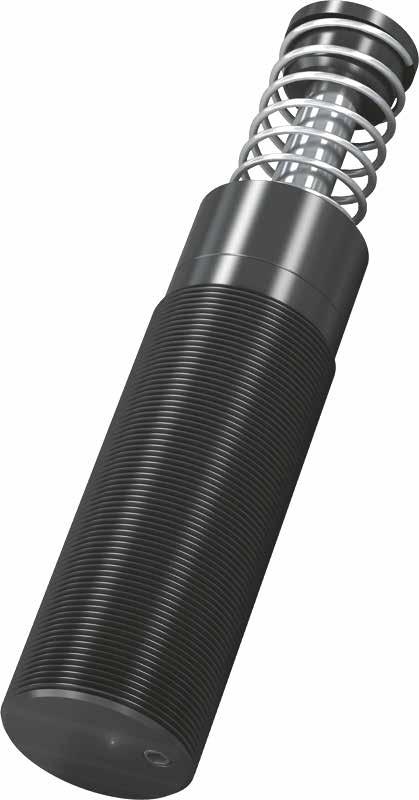

Standard & configured products available to buy online
Figure 2
Case study 2 A truck-mounted crane
Truck-mounted cranes offer a different set of load-holding challenges. These machines are commonly used to deliver materials to a construction site. For this particular application, the customer already had a solution in place that was expensive, but they were experiencing long lead times. At the same time, the customer was looking for improved control resolution for safer, more precise movement of materials from the truck.
The key to this solution also included choosing the right valve and applying it in a smart circuit. Since the customer was using a balanced load-control valve, we decided to stay with that approach. With a balanced load-control valve, system pressure does not need to increase for a lightly loaded crane hook. However, the balanced load-control valve does not provide thermal relief protection. A separate relief must be built into the circuit. Even the reduced system pressure present that is used to pilot the balanced load-control valve open can still be too high, causing stability issues from an overrunning load. One way to deal with this issue is to use an orifice divider to reduce pilot pressure. (Continued on page 10)
(Continued from page 9)
The challenge. Balanced load-control valves are attractive because the inverse relationship of pilot pressure needed to open the valve, which is higher for lighter loads, is replaced by a fixed pilot pressure required to open the valve regardless of the load pressure. However, in the traditional cross-piloted application where the cylinder piston-side counterbalance is piloted off the cylinder rod side or vice versa, the pilot pressure can end up being too high. The typical schematic is shown in figure 3. This sets up the actuator for an overrunning load condition that leads to the instability. In this situation, the valve over opens, the load overruns the pump supply, the pilot pressure collapses, and the valve closes. When the pressure recovers as the pump catches up, the valve is piloted open again, and the whole cycle repeats itself.
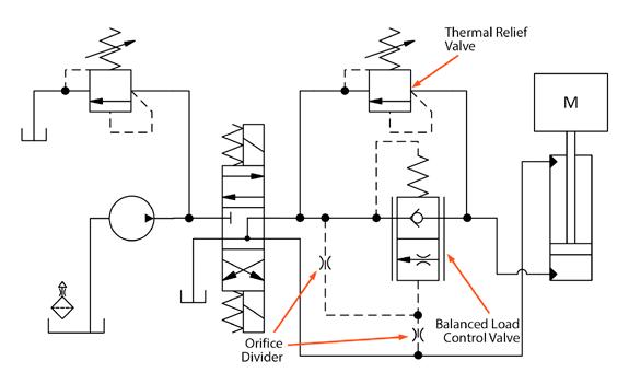
Figure 3
The solution. The use of an orifice divider can potentially solve the issue of too much pilot pressure on a balanced load-control valve that leads to an overrunning load and instability. The orifice divider acts to reduce the pilot pressure on the valve by bleeding some pilot flow off while restricting the

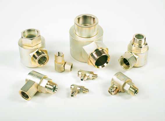
Figure 4
flow into the pilot, functioning much like a voltage divider in an electrical circuit. Since the balanced load-control valve does not offer relief protection, a separate thermal relief should be added at a minimum. It is important that this relief valve is a poppet-style valve to reduce leakage on the load-holding ports. Using needle valves instead of fixed orifices can allow for tuning, but this runs the risk of allowing the effective orifice sizes to be tuned small enough that the valve closing is too slow, resulting in a cavitating actuator. However, it can be useful when prototyping. And users should consider using a bypass check on the pilot inlet orifice to allow the counterbalance valve to close as fast as it needs to. Figure 4 gives an example circuit.
Different applications may need additions to the basic load-holding circuit to stabilize the load-holding valve, as the Federated Crane application demonstrated with the long payout of wire cable. In the example of the truckmounted crane, the situation demanded a valve that can provide precise control resolution, which means adding the orifice divider to keep the pilot pressure in the range the valve requires while preventing an overrunning load condition.
Introducing!
9S SERIES INVESTMENT CAST SWIVELS
The “9S” Series swivels represent one of the most complete range of sizes and configurations available to the industry. This series has been redesigned to incorporate a one piece barrel arrangement thus eliminating the need for braze joints. These swivels are pressure balanced with operating pressures up to 5,000 psi. All configurations are designed with a 4:1 Safety Factor and include RoHS compliant zinc plating.
P.O. Box 6479, Fort Worth, TX 76115 V. 817/923-1965 www.hydraulicsinc.com
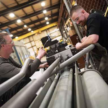
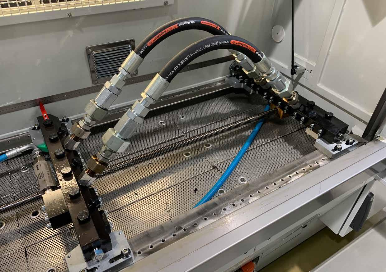
Hose assemblies installed in an impulse tester.
HOSE-COUPLING INTERFACES
By Matt Petti, Director of Global Product Line Management, Gates Corporation
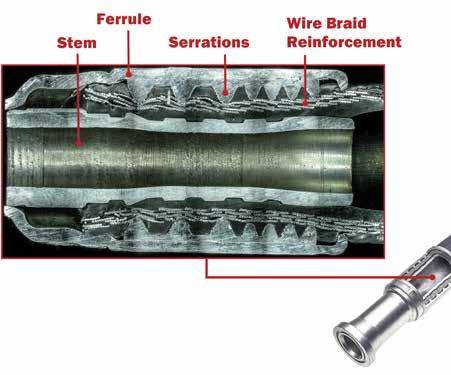
ydraulic hose assemblies are an integral part of a hydraulic system, withstanding thousands of psi of fluid pressure, powering the articulating arms of mobile construction equipment, the hydraulic ram of a 100-ton hydraulic press, and many other heavy-duty applications. The construction of a typical hydraulic hose assembly is relatively simple – a section of rubber hose with metal couplings crimped onto both ends. What is often overlooked is the interaction between the hose and the coupling after being crimped together, referred to as the hose-coupling interface. This carefully balanced combination of a metal ferrule, rubber hose, and coupling stem (also known as a hose insert) gives a hose assembly its overall pressure rating.
Both the hose and the couplings are designed for use at a certain working pressure, so it might be assumed that when combined, the assembly’s pressure rating would match the lesser rating of the two components. But the hose-coupling interface, a critical portion of a hose assembly, can often be the limiting factor when determining a complete assembly’s working pressure. To develop a dependable assembly working pressure and potential working life, there are several steps to the process. Choosing the correct ferrule, building a crimping profile and range, testing complete assemblies, including specific crimper settings, and recognizing sources of failure are all involved in the process of designing a reliable hose assembly.
To design couplings with a robust hose-coupling interface, there are variables such as the specific hose cover material, tube material, reinforcement layer thickness, and reinforcement ductility. When the ferrule component of a coupling is designed, these factors are taken into consideration and often affect the number and depth of the serrations lining the internal circumference of the ferrule. Many manufacturers of couplings intend for these serrations to penetrate the hose’s cover material and embed themselves in its reinforcement layer, creating a stronger bond with the hose when crimped. Gates calls this a “bite-the-wire” coupling. Also, in a proper crimp, the rubber of the hose flows between the serrations as it is being crimped, further improving the connection’s strength while minimizing intrusion from external elements. This is why ferrule design is closely tied to the type of hose, with some coupling families offering multiple types of ferrules, depending on the hose or application.
The first step in qualifying a coupling with a hose is identifying the correct ferrule to pair with the hose. For example, even if the hose inner diameter (ID) is known, it’s possible a different ferrule will be required for an SAE 100R1 hose versus a 100R2 hose because of the differences in hose outside diameter (OD).
(Continued from page 11) One-piece couplings come with a ferrule already attached, so the ferrule sizing is considered when choosing the complete coupling.
Once the correct coupling components are chosen to be qualified with a specific hose, the next step in qualification is to develop a manufacturer-provided crimp specification. This specification often refers to the final crimped OD of the coupling ferrule after it has been attached to a specific hose, measured using calipers on the flat portions across the ferrule diameter. To develop these crimp specifications, coupling development engineers estimate a target crimp OD using historical data and material property calculations. Engineers perform initial crimps using a hydraulic crimper, with a little trial and error to get to the target crimp OD. During crimping, due to the pressure exerted by the compression of the ferrule and rubber hose, engineers expect that the coupling stem has a certain amount of bore collapse. Using pin gauges or bore gauges (depending on the inner diameter), they take measurements to determine if there is too little collapse, resulting in a weaker clamping force between the ferrule and stem, potentially leading to coupling blowoff when pressurized. Too much collapse constricts the fluid pathway and decreases overall hydraulic system efficiency, in addition to potentially weakening the strength of the stem and leading to premature failure. Using the gauges, engineers compare the measured bore to the minimum bore allowed by SAE J516. They check the concentricity of the crimps and look for uniform crimping results around the circumference. They repeat subsequent crimping trials until they achieve an acceptable bore collapse, recording the crimp OD of the successful crimp result, which will then become the starting crimp OD for performance testing of that coupling-and-hose combination.

Testing
After determining a starting crimp OD, the real fun begins. The next step in the qualification process is testing the hose assembly under pressure, running it through several tests specified by industry standards like SAE J517 and J343 to determine the assembly’s integrity. Some of these tests are to ensure customer safety, using test parameters that allow for a sufficient safety factor to accommodate spikes in system pressure when in use in the field. Other tests in SAE J517 check the assembly's performance in simulated use, testing for things like hose dimension changes, hose degradation from external sources, and potential life of assemblies.
A few tests stipulated by SAE J517 are pertinent to the hose-coupling interface: the proof test, burst test, leakage test, and finally, the impulse test. Proof testing a hose assembly is a simple test that ensures the assembly is capable of holding pressure, requiring a hydrostatic pressure of twice the working pressure, held for 30-60 seconds, and checked for leaks at the coupling and along the hose length. After passing proof testing, select assemblies are tested for burst and leakage, putting the assemblies into extreme pressure conditions to see how they perform. Burst testing requires taking the assembly to a minimum of four times the working pressure, often higher, until the assembly has catastrophic failure. Leakage testing similarly pushes the assembly to its performance limits, bringing the pressure to 70% of the minimum burst pressure, held for five minutes, removing pressure, then repressurizing to 70% of minimum burst. After advancing through this pressure cycle, engineers check the assembly for leaks or signs of failure. All three tests have binary results, either pass or fail. crimp OD study. When they compile the data, they determine an optimum crimp OD using a statistical analysis of the best performing samples. The crimp OD they discover through this process becomes the specified crimp OD for use by hose assemblers.
Providing settings
The last step for a manufacturer who offers crimpers in their product line is to make the crimping process easier for their customers by providing crimper-specific settings to reach the specified crimp OD. For example, Gates publishes crimp specifications for its hose-coupling combinations with crimpers and dies in a printed manual as well as on their eCrimp website and mobile app. While some high-volume production-grade crimpers can program a specified crimp OD into their user interface, many crimpers do not have a direct method to tie machine settings to crimp OD. When there
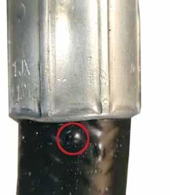
The result of a coupling blowoff during testing. Blisters formed under the hose cover during testing. Cover bulge from a bad crimp.
The last test for hose-coupling interface evaluation is impulse testing. While impulse testing can have a binary result of whether it passes industry standard minimum impulse cycles, it is often run beyond industry minimums to test how long the hose assembly could potentially last in high-impulse cycle applications. The hose assembly, made to the proper length to allow the rated minimum bend radius, is attached to the manifold inside of an impulse tester, and the assembly is subjected to a repetitive pulsation of temperature-controlled hydraulic fluid through the hose at a frequency specified by SAE J343. This cycling of pressure mimics the pressure changes in a hydraulic system of a customer’s machine, although at an accelerated rate. This allows the hose performance to be evaluated in a number of days in a laboratory environment as opposed to weeks or months of field testing. During impulse testing, engineers use a range of crimp ODs above and below the starting crimp OD across several hose samples, recording the number of cycles each sample achieves before failure. When testing over a crimp range, they expect “edge failures,” where the ends are over-crimped or under-crimped, reinforcing the results of the are a variety of crimper models and die sets available, it can be an arduous task to develop crimp settings for each hose size, coupling type, die set, and crimper model. The process often begins by loading the correct die set into a crimper, determined by the closure for that specific die set. Using historical machine settings with the specific die set, engineers adjust the crimper to an estimated setting that should achieve the specified crimp OD. A series of crimp trials narrows the machine settings to hit a crimp OD within a specific tolerance above and below the specified crimp OD. The allowable tolerance varies from manufacturer to manufacturer. Engineers repeat this process for each available crimper model and record machine settings for assemblers to quickly dial in crimps during assembly production.
The effort that goes into qualifying hydraulic hose-coupling combinations ensures a reliable, high-quality hose assembly that meets performance expectations while maintaining customer safety as the highest priority. When a scientific, repeatable qualification process isn’t performed to verify a hose-coupling combination, the consequences can range from inconvenient leaking to catastrophic failure. We can attribute some failures
in hose assemblies to the hose, as with a pinhole burst or poor wire-reinforcement construction. We can attribute other failures to the application, such as an over-tight bend radius or a bend near the coupling that puts increased strain on the hose-coupling interface. There are also failures specific to coupling design, such as leakage of hydraulic fluid at the termination or mechanical failure of coupling components from over-torquing the termination.

Interface failures
Failures at the hose-coupling interface are a focus during the qualification process and can differ from the failures attributed to individual components, resulting instead from the combination of the hose and coupling. A common failure is a visible drip of hydraulic fluid exiting the coupling ferrule where it meets the hose, often resulting from a nonconcentric crimp or improper die closure. While rubber is an ideal material for hydraulic hoses because of its flexibility and durability, the integrity of the rubber in the hose-coupling interface area can degrade over time, particularly when exposed to high-temperature hydraulic fluid for hundreds of thousands (even millions!) of impulse cycles, which can also cause weeping of fluid at the hose-coupling interface over time. A more difficult failure to
Crimp specifications shown in the Gates eCrimp app.
diagnose is a leak caused by poor crimping in which the hydraulic fluid escapes the hose-coupling interface between the hose’s tube and cover layer, travelling down the reinforcement wire or fiber until it creates a blister in the hose cover or creates a pinhole leak. The most severe failure at the hose-coupling interface is called coupling blowoff. This often occurs from a crimp with insufficient compression and bore collapse, resulting in a loose connection of the coupling to the hose. While the crimp may appear to be satisfactory at initial pressurization, as the assembly is submitted to hundreds of thousands of impulse cycles by the hydraulic pump, the coupling in a loose crimp can separate from the hose at extremely high speeds, spraying hydraulic fluid in the process, creating a very dangerous scenario. Causes for these hose-coupling interface failures in the field are often found during lab testing, further reinforcing the importance of the qualification process.
When couplings and hoses are specifically designed to be compatible with each other, it greatly increases the chance of creating a high-quality, long-lasting, safe hose assembly. Completing a thorough, scientific qualification process further guarantees not only the compatibility of the hose and coupling but empowers the various parties responsible for crimping hose assemblies with the necessary guidance to create repeatable, reliable crimped assemblies. Ensuring that the coupling and hose are from the same manufacturer and that crimp specifications exist for the combination from that manufacturer improves performance and reliability. The risk assumed by combining couplings and hoses that have not been qualified by their manufacturers is significant, as the possibility of failure dramatically increases and can be severe.
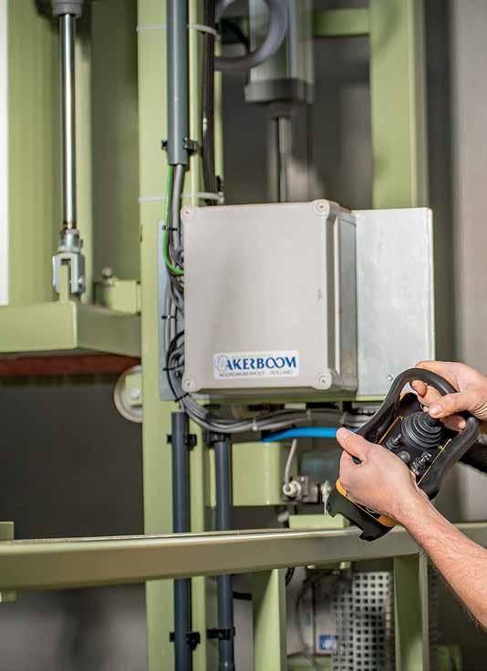
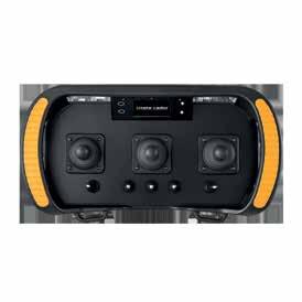
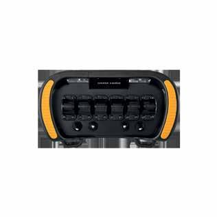
SAFE SMART STRONG REMOTE CONTROL FOR HYDRAULIC APPLICATIONS