


Innovation starts with Bosch Rexroth and HydraForce. Our expert application engineers design efficient electro-hydraulic systems, delivering compact hydraulic solutions that enhance machine performance. Whether it’s an upgrade, redesign or new motion control application, rely on our global team to help you gain a competitive edge.


Proportional Directional Control Valve Systems for Mobile Hydraulics
As presented by Randy Bobbitt, CFPS, Danfoss Power Solutions.
Transforming the Closed Die Forging Industry
Fluid power professionals embrace the digital shift to redefine the future of manufacturing.
TEST YOUR SKILLS
Understanding the Supply Chain
Stay sharp with this monthly lesson from the IFPS's study guide.
Lubricants: Unsung Heroes of Sustainability
The lubricants industry leads the charge toward a greener future.
The Hidden Power of Servo Valve Technology
How servo valves power precision in modern fluid power systems.
The Critical Role of Pressure Transducers, Tachometers, and Hydraulic Systems
The military industry increases reliability and performance to ensure reliability in its vehicles.
Lower Compressed Air Consumption and Improve Machine Performance
Six easy-to-apply energy savings design tips for pneumatic systems.
Publisher’s Note: The information provided in this publication is for informational purposes only. While all efforts have been taken to ensure the technical accuracy of the material enclosed, Fluid Power Journal is not responsible for the availability, accuracy, currency, or reliability of any information, statement, opinion, or advice contained in a third party’s material. Fluid Power Journal will not be liable for any loss or damage caused by reliance on information obtained in this publication.


By Donna Pollander, IFPS CEO

» AT THE INTERNATIONAL Fluid Power Society (IFPS), our mission goes beyond certification. We’re here to support the entire lifecycle of a fluid power professional—through education, training, and a deep-rooted commitment to safety.
Over time, IFPS has evolved into a dynamic global organization that supports mechanics, technicians, sales professionals, engineers, and educators across the fluid power industry—whether they are users, distributors, or manufacturers. Whether on the shop floor, in a classroom, or designing the next generation of hydraulic or pneumatic systems, we’re here to provide the tools and support you need to succeed. From on-demand videos and study guides to hands-on training and safety resources, IFPS is proud to be the industry’s trusted source for professional development.
Currently, we host more than 75 educational videos on our website—many of them free to the public, and even more accessible to members. We provide modular, self-paced training options for several of our eleven certification tracks, making it easier for professionals to pursue credentials on their own schedules. Robust safety guidelines and best practices
are integrated into all of our certifications and study guides, and are continually updated in collaboration with industry experts.
Certification at IFPS is more than a credential—it’s a reflection of practical knowledge and job-ready expertise. Our programs are built around real-world applications and tailored to specific industry roles, from mechanics to system designers. Whether pursuing a Hydraulic Specialist, Pneumatic Specialist, or Mobile Hydraulic Mechanic certification, professionals can count on IFPS to set high standards and help them reach them.
Two certifications I would like to highlight are our Fluid Power Support Associate (SA) certification and our Electronic Controls Certification (ECS).
The Fluid Power Support Associate (SA) is a new certification designed for individuals who are either entering the industry or working in non-technical roles. It ensures a foundational understanding of fluid power terminology and basic components. Many companies use the SA certification as a stepping-stone to more technical certifications and have used the training modules as an effective onboarding tool to introduce new team members to fluid power fundamentals.
The Electronic Controls Specialist (ECS) certification has been fully updated to reflect advancements in electrohydraulic/pneumatic technology. It is ideal for professionals seeking to validate their skills in electronic control systems; this certification covers system integration, sensor technologies, closed-loop control, and current industry standards. It’s an essential credential for staying competitive in today’s increasingly digital fluid power landscape. The study manual is also an excellent desktop reference for all those working with electronic controls of fluid power!
Beyond certification, we are deeply committed to education. Our reference materials, webinars, and training tools are designed to support working professionals and students alike. The Fluid Power Reference Handbook, widely used in industry and academia, remains a cornerstone of our educational offerings.
We also recognize that safety is not optional in this line of work—it’s essential! Every IFPS certification integrates safety education, covering topics such as lockout/tagout procedures, hose handling, and fluid injection injury prevention. Our goal is simple: ensure that every individual trained and certified through IFPS can work confidently and safely.
One of the most valuable aspects of IFPS is our community. We are proud to bring together thousands of professionals from across the globe. Through mentorship programs, technical workshops, annual meetings, and volunteer opportunities, we create space for connection, leadership, and shared learning.
For employers, the benefits of IFPS certification are clear. Certified professionals are safer, more productive, and more engaged. Companies that invest in training through IFPS report more employee confidence, stronger problem-solving, and higher retention rates across the board.
As the industry continues to evolve, IFPS is evolving right alongside it. We’re committed to ensuring our certifications, training, and educational programs remain relevant, effective, and forward-thinking.
To all fluid power professionals, whether you’re just starting out or decades into your career—I invite you to explore everything IFPS has to offer. Together, we can build a smarter, safer, and stronger future for our industry.
Innovative Designs & Publishing, Inc.
3245 Freemansburg Avenue, Palmer, PA 18045-7118
Tel: 800-730-5904 or 610-923-0380
Fax: 610-923-0390 • Email: Art@FluidPowerJournal.com www.FluidPowerJournal.com
Founders: Paul and Lisa Prass
Associate Publisher: Hannah Coursey
Editor: Lauren Schmeal
Technical Editor: Dan Helgerson, CFPAI/AJPP, CFPS, CFPECS, CFPSD, CFPMT, CFPCC
Senior Marketing Consultant: Bob McKinney
Graphic Designer: Nicholas Reeder
Accounting: Kim Kressman
Circulation Manager: Josh Shoup
INTERNATIONAL FLUID POWER SOCIETY
1930 East Marlton Pike, Suite A-2, Cherry Hill, NJ 08003-2141
Tel: 856-424-8998 • Fax: 856-424-9248
Email: AskUs@ifps.org • Web: www.ifps.org
2025 BOARD OF DIRECTORS
President: Garrett Hoisington, CFPAI, CFPS, CFPMHM
Immediate Past President: Jeff Hodges, CFPAI/AJPP, CFPMHM - Altec Industries, Inc
First Vice President: Chauntelle Baughman, CFPHSOneHydraulics, Inc.
Treasurer: Elisabeth DeBenedetto, CCFPS, GS Global Resources
Vice President Education: Daniel Fernandes, CFPS, CFPECS, Hawe Hydraulics
Vice President Membership: Brian Wheeler, CFPAI/AJPP - The Boeing Company
Vice President Certification: Bruce Bowe, CFPAI/AJPP - Altec Industries, Inc.
Vice President Marketing: Bradlee Dittmer, CFPPS - IMI Precision Engineering
DIRECTORS-AT-LARGE
Tyler Janecek, CFPHS - Engineering Systems, Inc
John Juhasz, CFPS - Kraft Fluid Systems
Stephen Blazer, CFPE- Altec Industries, Inc. Brian Kenoyer, CFPS - Cemen Tech
Jeff Curlee, CFPS -Cross Mobile Hydraulics & Controls
Quest Duperron, CFPIHM, CFPCC - Coastal Hydraulics, Inc.
Cary Boozer, CFPE - Motion Industries, Inc.
Steven Downey, CFPAI, CFPS - Hydraulex Deepak Kadamanahalli, CFPS - CNH Industrial Kyler Craig Ridgeway, CFPHS - Bradbury Company Alex Kummer, CFPE, - National Oilwell Varco Wade Lowe, CFPS - Hydraquip Distribution, Inc.
CHIEF EXECUTIVE OFFICER (EX-OFFICIO) Donna Pollander, ACA
HONORARY DIRECTOR (EX-OFFICIO) Ernie Parker, Hydra Tech, Inc. CFPAI/AJPP
James O'Halek, CFPAI/AJPP, CFPMM, CFPMIP, CFPCCThe Boeing Company
IFPS STAFF
Chief Executive Officer: Donna Pollander, ACA
Communications Coordinator: Stephanie Coleman
Director Training/Development: Bradley (BJ) Wagner, CFPAI/AJPP
Assistant Director: Jenna Mort
Certification Logistics Manager: Kyle Pollander Bookkeeper: Diane McMahon
Instructional Designer & Layout: Chalie Clair
Fluid Power Journal (ISSN# 1073-7898) is the official publication of the International Fluid Power Society published monthly with four supplemental issues, including a Systems Integrator Directory, Off-Highway Suppliers Directory, Tech Directory, and Manufacturers Directory, by Innovative Designs & Publishing, Inc., 3245 Freemansburg Avenue, Palmer, PA 18045-7118. All Rights Reserved. Reproduction in whole or in part of any material in this publication is acceptable with credit. Publishers assume no liability for any information published. We reserve the right to accept or reject all advertising material and will not guarantee the return or safety of unsolicited art, photographs, or manuscripts.
By Robert Sheaf, CFPAI/AJPP, CFPE, CFPS, CFPECS, CFPMT, CFPMIP, CFPMMH, CFPMIH, CFPMM, CFC Industrial Training
» A CUSTOMER REBUILT one of his old machines and upgraded it to provide variable motor speeds. He added a SUN proportional valve with electronic controls for the variable speeds. The valve model was a FPBF-XDN pilot-operated throttle screw-in cartridge. This was the only item added to the original machine, and the circuit drawing shown. The circuit symbols for the pressure controls, the pilot-operated directional valve, and the pressure compensated (PC) pump are how they were shown when the machine was built many decades ago.
He complained that his machine was pulsating at certain feed rates. He was advised to add a Hydrostat, a pressure-reducing valve internally drained to the throttle’s outlet, to the circuit. This provided pressure compensation to the throttling valve, but it did not ultimately solve the problem.
He disconnected the motor from the machine. With it just lying on the floor, it pulsed drastically at most RPMs. At low speed, it would stop and start off and on. Lowering the safety relief below the pump compensator setting and running the motor eliminated the pump compensator as the pulsation problem. The 2 MPa (300 PSI) pilot supply to the directional valve was constant, as well as the mA signal to the throttle valve coil. When a slight force was applied to the motor shaft by creating friction from a shoe, the pulsing slowed and then stopped after about 10 seconds. From there, the motor ran smoothly at the expected RPM.
Any thoughts on what caused the problem?
For the solution, see page 29.
Robert Sheaf has more than 45 years troubleshooting, training, and consulting in the fluid power field. Email rsheaf@cfcind.com or visit his website at www.cfcindustrialtraining.com. Visit fluidpowerjournal.com/figure-it-out to view previous problems.

By Lauren Schmeal, Editor, Fluid Power Journal
As presented by Randy Bobbitt, CFPS, Danfoss Power Solutions
Mobile hydraulics has undergone a fascinating evolution over the years, driven by technological advancements and market demands. This article delves into the history, challenges, and pivotal trends in mobile hydraulic valve systems, with a focus on the transition from early traditional hydraulic controls to modern solutions incorporating electronics and autonomous technologies.
In the mid-70s, mobile hydraulics was still in its pioneering phase. Hydraulic control valve systems were in mobile equipment, but they came with significant challenges. Hydraulic control valve systems came at a high cost and were expensive to implement and maintain. Operators found it difficult to achieve precise control due to control complexity including the lack of advanced feedback mechanisms. Many hydraulic control valve systems consumed excessive fuel, especially during prolonged operations; this caused undesired levels of energy inefficiency. Despite these limitations, hydraulics was a proven technology that powered critical machinery in industries such as construction and agriculture.
The late 1970s and early 1980s saw increasing demands for more efficient and reliable hydraulic control valve systems. Key drivers included:
• Energy Efficiency: Fuel efficiency became a priority due to rising fuel costs; especially in Europe. Hydraulic control valve systems had to be redesigned to minimize energy losses while maintaining performance and be able to communicate with Load Sense pump systems, a game changer for highest energy savings.
• Higher Performance on Smaller, lower horsepower Machines: Manufacturers sought ways to enhance the performance of compact machines without significantly increasing their size or complexity.
• Increased Use of Electronics: The integration of electronics into hydraulic
control valve systems began during this period. However, the technology was still in its infancy. Electronics were primarily analog and discrete, and microcontrollers were rare and expensive.
• Reliability and Longevity: Designing for reliability became a core focus. Hydraulic control valve components were engineered to last between five to eight years under rigorous conditions.
To address these challenges, engineers introduced several innovations:
• Modular Design: Hydraulic control valve systems became more modular, enabling manufacturers to easily optimize components for different machine types and applications. Easy serviceability was key.
• Precise Flow Control: Control valves were redesigned for better precision. Open-loop flow control systems enabled operators to deliver consistent flow rates with minimal effort.
• Operator-Friendly Controls: Lever operated control valves were optimized for ease of use: Main Spool Centering spring force and flow control notch orifice design ensured lower operator efforts, promoting smooth operation and improved ergonomics.
• Advanced Spool Designs: Control spools were refined to minimize leakage and pressure drops, even at high operating pressures upwards of 35 MPa (5,000 psi).
Electronics revolutionized mobile control valve hydraulics by enabling proportional control; specifically, precise adjustments based on input signals. Sensors provided real-time data for better system regulation via effective feedback mechanisms. Additionally, operators were able to control machinery remotely from safe distances, thus improving safety and productivity. Europe led the charge in implementing functional safety standards for hydraulic systems. These
standards ensured that machines operated reliably under all conditions, reducing risks for operators and equipment.
One critical aspect of mobile control valve hydraulics during its early evolution was operator fatigue. Lever operated hydraulic control valve systems often required skilled operators who could manage complex controls over long hours of operation. The lack of ergonomic design meant these operators frequently experienced physical strain, impacting productivity and precision. Manufacturers gradually began addressing these issues by optimizing the main control spools to lower the spool flow force efforts and spring load efforts—making operations easier reducing wear on the seasoned professional.
The intricacies of pressure dynamics within hydraulic control valve systems posed another challenge during this era. Operators needed to manage precise flow rates through control valves while dealing with varying loads on
machinery work functions. This was easy and predictable for the seasoned professional but challenging for the inexperienced operator. Electrical proportional control development was also challenged by the wide variance in spool force inconsistencies with the technology of the time. The solution was discovered with the development of advanced pressure compensated spool design with tighter flow tolerances to minimize pressure drops across the main control valve spool, ensuring consistent performance and the lowest spool flow force efforts even under high-pressure load conditions upwards of 35 MPa (5,000 psi). These innovations improved ergonomics, electro-proportional flow precision, energy efficiency and performance while maintaining reliability across diverse applications.
Proportional control marked a significant leap forward in mobile control valve hydraulics technology. By introducing analog electronics capable of delivering precise adjustments based on input signals, manufacturers enabled operators to fine-tune flow rates more effectively than ever before. This advancement laid the foundation for modern CAN based hydraulic
control valve systems that incorporate digital sensors and microcontrollers—paving the way for automation and remote operation capabilities seen today.
Today, mobile control valve hydraulics is moving toward CAN based autonomous solutions. Hydraulic control valve systems are being integrated into autonomous, self-driving construction equipment. Sensors and on-board electronics monitor control valve system health providing predictive maintenance reporting, predicting failures before they occur.
The evolution of mobile control valve hydraulics reflects a relentless pursuit of efficiency, precision, and reliability. From the analog controls of the 1970s to today's autonomous technologies, each innovation has addressed specific challenges while paving the way for new possibilities. As we look ahead, the integration of electronics, functional safety standards, and autonomous capabilities will continue to shape the future of this vital industry. •


By Bishwajit Ranjan, PE, PMP, CMRP, CFPE, MBA, Director, Plant Services, Ellwood Texas Forge Houston
Today’s manufacturing industries rely heavily on fluid power systems to convert raw materials into usable products. Efficient handling of a large amount of energy by fluid power systems to facilitate manufacturing under close tolerances is the key to success in today's competitive market. The upkeep of fluid power systems is critical in achieving
the world-class quality products needed by customers. It is also vital to control the cost of production and operate in an environmentally friendly manner. This ensures a value-added product offering with long-term sustainability.
During my global career of more than 30 years, I was privileged to gain experience in diverse industrial environments ranging from
heavy equipment manufacturing, marine and oil field refurbishment, hot strip mill, and plate mill, along with aerospace, defense, and industrial manufacturing. In all these facilities, the fluid power components used were the same as HPUs, various control and servo valves, and a multitude of actuators. Still, the application and the attributes that
are critical for product quality differ vastly from industry to industry.
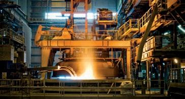
Tandem rolling mills rely heavily on fast-response closed-loop servo valve controls to ensure optimum automatic gauge control and proper tension. They are maintained by Interstate loopers controlled by servo proportional valves to ensure uniform width across a one-mile-long strip. Meanwhile, the expansion and collapse of the down coiler mandrel and the accurate opening of the wrapper roll cylinders by executing pressure and position control ensured a well-built “Hot Rolled Coil” as the final product.
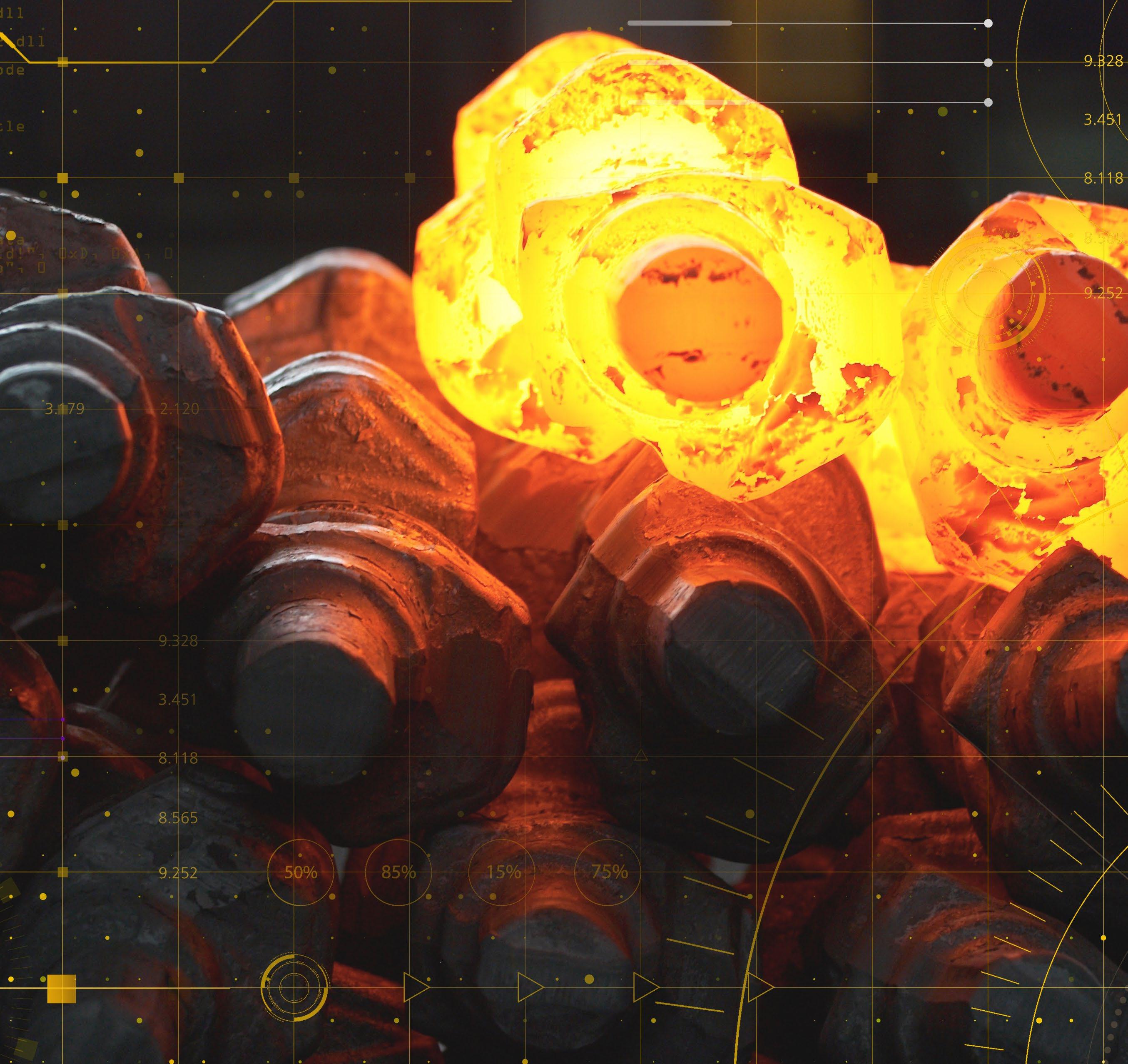
In comparison, close die forging requires a slow and gradual build of tonnage by stepped loading of pumps and recipe-controlled tonnage control. This achieves velocity and pressure control, followed by a ramped multistage decompression. It dissipates thousands of tons of energy built during the forge process, with a smooth ejection of the part. In one application, simultaneous loading of pumps and fast response servo/proportional closed-loop controls were critical. In another application, the slow but steady modular loading of pumps and accurate set points for opening and closing control valves did the job.


It is fascinating how the same fluid power systems with different concepts of control were utilized to accomplish the goal. Though the basics of fluid power system design and maintenance best practices change marginally on the macro level, it is of utmost importance for fluid power engineers to understand the application and the desired attributes of the final product. It’s also important to note that fluid power systems are optimized at the micro level to perform at peak efficiency and consistently deliver quality.
In the 3rd decade of the 21st century, every seminar and discussion forum revolves around the transition to Industry 5.0. A solid understanding of fluid power systems for a specific manufacturing process is of utmost importance. After spending several decades in the North American closed die forging industry for aerospace manufacturing with two key players, Ellwood and Wyman Gordon, and working with numerous forging presses, there is no doubt that the optimization and upgrade of fluid power systems in the closed die forging industry is a journey and not the destination. It is continuously driven by ever-increasing aviation safety norms, plant
safety needs, sustainability best practices, and cost considerations. By using the latest technologies, including big data and cloud computing powered by AI-supported analytics, there is great potential to reshape the way fluid power is optimized and operated.
When observing the closed die forging Industry in North America, it’s noteworthy that most large presses were built 40-60 years ago. Over the years, most press controls have been upgraded to some extent; even robotics and automation are being added, but basic fluid power systems remain the same. Introducing advanced manufacturing technologies and automation requires fluid power systems to function at a much higher degree of accuracy and speed.
Limit and proximity switches are replaced by position transducers, and control relays are replaced by the latest generation processors. The needs connected with the automation call are to evaluate the entire fluid power system and anticipate the scope of upgrade required to support the automation. In some cases, press upgrades provide the opportunity to add new, innovative fluid power systems equipped with the latest PDM sensors and servo-controlled


h as tonnage, velocity, deformation time, and transfer times, using AI models to analyze the gaps between actual and desired values. This can drive optimization via real-time corrections, saving millions of dollars wasted in the form of non-conformances and scraps. Consequently, this improves on-time delivery to the customers.
The modern iteration of CMMS offers integration with industrial control systems, HMIs, and SCADA to import valuable data from sensors, analyze them with AI-powered systems, and present them in the form of executable work orders. At a time when many people in the maintenance and operation workforce are about to retire, this type of integration can be especially beneficial for a younger workforce with limited experience.
While the road to automation and digitalization appears very lucrative and straightforward, we must foresee the implementation challenges and plan to navigate successfully through these potential obstructions. For instance, cybersecurity is a big deal in the aerospace and defense sectors. Additionally, CMMS providers must comply with the stringent security requirements of the industry while offering integration with industrial control and automation systems

through the plant network. Increasing awareness of the capability of digitization and AI-powered automation among plant maintenance, operation, and reliability professionals is a challenge, but it helps them buy into the new technology. They may offer valuable suggestions during implantation, making the transition more useful for the organization. Finally, a thorough analysis of the investment towards automation projects and accurate estimation of the resulting payback will help projects garner sponsorship and support from management.
With Industry 5.0, we are in the crucial age of transformation, where digitization, cloudbased, and AI-powered technologies are no longer alien concepts and are redefining the future of manufacturing. It is imperative to leverage cutting-edge technologies to keep our business efficient and competitive. The challenge is how fluid power professionals adapt to these new technologies to create a landscape that makes the best sense to our specific business needs and the markets we cater to. The choice is ours, if we want to ride the wave and take our organizations and the industry to new heights or be left behind. As a wise man once said, “Time and tide wait for no man.” •

» THE LATEST DATA published by the National Fluid Power Association shows March 2025 total fluid power shipments increased 12.6% from the previous month and are 6.1% below March 2024’s index. 3/12 and 12/12 rates of change for total fluid power, hydraulic, and pneumatic shipments are negative, and their downward movement appears to be plateauing. The data and charts above are from NFPA’s Confidential Shipment Statistics (CSS) program where over 70 manufacturers of fluid power products report their monthly orders and shipments. More market information is available to NFPA members, allowing them to better understand trends and anticipate change in fluid power and the many customer markets it serves. Contact NFPA at 414-778-3344 for more info.
INDEX DATA: 3 MONTH MOVING AVERAGE & 12 MONTH MOVING AVERAGE
This graph of index data is generated by the total dollar volume reported to NFPA by CSS participants. This graph uses moving averages to smooth out the data and clearly identify trends. (Base Year 2024 = 100).
PNEUMATIC, MOBILE HYDRAULIC, AND INDUSTRIAL HYDRAULIC
INDEX DATA: 12/12 RATE OF CHANGE
Each point on this graph represents the most recent 12 months of shipments compared to the previous 12 months of shipments. For example, 7.3% (the August 2023 level of the pneumatic series) indicates that the value of pneumatic shipments from September 2022 to August 2023 were 7.3% higher than the value of pneumatic shipments from September 2021 to August 2022.
MOBILE
AND INDUSTRIAL HYDRAULIC
INDEX DATA: 12/12 RATE OF CHANGE
Each point on this graph represents the most recent 12 months of orders compared to the previous 12 months of orders. For example, 8.5% (the August 2023 level of the industrial hydraulic series) indicates that the value of industrial hydraulic orders received from September 2022 to August 2023 were 8.5% higher than the value of industrial hydraulic orders received from September 2021 to August 2022.
The table above shows various rates of change for the month of September 2024. Interpretation for each rate of change calculation:
- M/M %: The percent change between the current month and the previous month.
- Y/Y %: The percent change between the current month and the same month one year ago.
- 3/12 %: The percent change between the three most recent months and those same three months one year ago.
- 12/12 %: The percent change between the twelve most recent months and those same twelve months one year ago.
*Preliminary data subject to revision.

1
Asupply chain is a system of people, organizations, and activities that work together to move goods or services from the supplier to the end customer. The supply chain can be thought of as a series of links in a chain, with each link representing a different stage of the process of getting a product or service to a customer.
In business, a supply chain starts with the raw materials that are used to make a product,
moves through manufacturing, then transportation, then warehoused and stored in a distribution center before being sold, and ending with delivery of a finished product to a customer. Each stage in the supply chain is critical for making sure that the product is produced efficiently, shipped to the right place, and delivered to the customer on time. •
What is included in the supply chain?
a. The use of a product after it has been sold to the end customer.
b. The manufacturing process only.
c. The shipping of a product.
d. Manufacturing, transportation, warehouse/storage, and delivery to end customer.
e. None of the above.
See page 29 for the solution.
» THE INTERNATIONAL FLUID Power Society (IFPS) offers a suite of training tools designed to enhance the skills and knowledge of professionals in the fluid power industry. These resources cater to various learning preferences and professional levels, ensuring that individuals can find the right tools to meet their specific needs.
Among the offerings are online training modules that provide interactive, self-paced learning experiences. These modules cover a range of topics, including hydraulic and pneumatic systems, and are ideal for those preparing for certification exams or seeking to deepen their understanding of fluid power concepts. The modules incorporate features such as animated circuits, voice-over explanations, and interactive quizzes to reinforce learning.
In addition to online modules, IFPS provides study manuals, technical posters, and
review training PowerPoint presentations. These materials serve as valuable references for both individual learners and instructors. For organizations seeking tailored training solutions, IFPS offers custom technical training programs that can be delivered in-person or virtually, focusing on specific machinery and personnel requirements.
By utilizing these comprehensive training tools, professionals can stay current with industry standards and best practices, ultimately contributing to safer and more efficient workplaces.
DIVE INTO IFPS'S FLUID POWER FUNDAMENTALS COURSE
» UNDERSTANDING THE BASICS of fluid power is crucial for anyone involved in the design, maintenance, or operation of hydraulic systems. The IFPS Fluid Power

Fundamentals course offers an in-depth exploration of essential concepts, providing participants with the knowledge needed to excel in the field.
This eight-session online course covers topics such as hydraulic principles, system components, symbology, and contamination control. Designed for a diverse audience— including customer service representatives, engineers, and maintenance technicians—the course combines theoretical instruction with practical applications. Participants engage in interactive sessions that facilitate a deeper comprehension of fluid power systems . Upon completion, attendees receive a certificate from IFPS, signifying their grasp of fundamental fluid power concepts. The course also includes a comprehensive student workbook, serving as a valuable resource for future reference. By investing in this foundational education, professionals can enhance their problem-solving abilities and contribute to the overall efficiency of their organizations.
» THE IFPS ANNUAL Meeting is a premier event that brings together professionals from across the fluid power industry to discuss advancements, share insights, and shape the future of the field. Scheduled for September 29 to October 2, 2025, at the Hilton Salt Lake City Center, this gathering offers a unique opportunity for networking and professional development.
Attendees can look forward to a variety of sessions, including technical presentations, panel discussions, and workshops led by industry experts. The meeting also provides a platform for participants to engage with peers, exchange ideas, and explore collaborative opportunities. Whether you're a seasoned professional or new to the industry, the Annual Meeting is an invaluable experience that fosters growth and innovation.
Registration for the event opens in July 2025. For additional information and to secure your spot, visit the IFPS meetings page. Don't miss the chance to be part of this influential event that continues to drive the fluid power industry forward.
AI
David Spitzenberger, Fluid Power Training
Guy Roberts, The Boeing Company
CC
Angel Rodriguez
Bryan Boyd, Ballinger Industries, LLC.
Connor Vlist-Okelley, The Boeing Company
David Holt, The Boeing Company
Jason Bates, The Boeing Company
Jensen Ballinger, Ballinger Industries, LLC.
Johnny Jackson, Custom Hydraulics & Design, Inc.
LaMar Ballinger, Ballinger Industries, LLC.
Mitchell Ratigan, The Boeing Company
Nick Ballinger, Ballinger Industries, LLC.
Robert Rudisill, Custom Hydraulics & Design
Taylor Newby, The Boeing Company
Tyler Hayes, The Boeing Company
E
Olaf Pippel
Will Long, Gerdau
HS
Aaron Stewart, GS Global Resources
David Ermel, NOV Hydrarig Fort Worth
David Harkins
Declan Lockwood, Hydraquip
Gage Wright, GS Global Resources
Jacob Wierzbinski, GS Global Resources
John Jensen, Engineered Sales, Inc.
Kakkinje Mohammed Irfan, Alaa for Industry
Kyle Konvicka, Hydraquip
Luke Lovato, Flint Hydraulics Inc
Matthew Collins, Price Engineering/ SunSource
Mitchell R Baker, JARP IND.
Patrick McSorley, Equipment Tramac Ltee
Rajesh Belani, welspun tubular
William Minick, Hydraquip Inc.
Zachary Klokow, Manitowoc Cranes
IHM
Andrew Sprigle, RG Group
Austin Knaub, RG Group
Christian Whalen, The Boeing Company
Dean Schopf, RG Group
Jonathan Vasold, RG Group
Kate Brown, RG Group
Ken Parramore, RG Group
MHM
Andrew Greeninger, Altec Industries, Inc.
Caleb Matthews, Altec Industries, Inc.
Chad Smitley, Altec Industries, Inc.
Eric Triebwasser, Altec Industries, Inc.
Francisco Castro, Altec Industries, Inc.
Joshua Escobar, Altec Industries, Inc.
Kenneth Grubb, Altec Industries, Inc.
Martin Garcia, Altec Industries, Inc.
Mason Lauer, Wilson Construction
Miguel Puente, Altec Industries, Inc.
Nathan Rammell, Altec Industries, Inc.
Robert White, Altec Industries, Inc.
Shane Hobbs, Altec Industries, Inc.
Travis Coots, Altec Industries, Inc.
PS
Adam Engeldinger
Brady Enger
Efren Rubio
Erik Dahlman, Loram Maintenance of Way
Grant Larson
Jason Mawhirter
Jonathan Schmidt, Neff Press Inc.
Malachi Martichuski
Mark Thole
Owen Christenson-Hough
Ryan Butala, Force America Inc
Thomas Yarick, Parker
Tyler Herbruck
S
Adam Engeldinger
Brady Enger
Efren Rubio
Erik Dahlman, Loram Maintenance of Way
Grant Larson
Jonathan Schmidt, Neff Press Inc.
Malachi Martichuski
Mark Thole
Owen Christenson-Hough
Ryan Butala, Force America Inc
Tyler Herbruck
SA
Aaron Tucker, SFP
Alaina Alberts, SFP
Caleb Owensby, SFP
Codee Stuffel, SFP
Coy Lewis, SFP
Jill Roach, SFP
Joseph Shoars, SFP
Justin Johnston, SFP
Kevin Cambron, SFP
Kyle Morton, SFP
Martin Gonzales
Michael King, SFP
Stephanie Fenison, SFP
A SPOTLIGHT ON CREATIVITY AND ADVENTURE: CHALIE CLAIR, INSTRUCTIONAL DESIGN/LAYOUT
» AT THE IFPS, every team member is vital in advancing the organization's mission. The team is made up of talented individuals who bring passion and expertise to their work. Today, we’re excited to introduce you to a talented team member. Chalie, the IFPS instructional designer and layout designer, plays a crucial role in enhancing experiences for members throughout all industries that utilize fluid power. This includes our areas of focus for this issue: medical, food processing, and plastics.
One of the aspects Chalie enjoys most about his role is the creativity it allows. Whether developing new materials or refining existing ones, he takes pride in making learning more accessible and engaging. “My job allows me to combine technical expertise with creativity, which is my favorite part of the position,” he shared. A passion for innovation fuels his work, bringing fresh ideas to life for learners across the industry.
Creativity doesn’t stop at work for this design expert—it extends into his interests as well. When asked about his favorite movie, Chalie enthusiastically named Eternal Sunshine of the Spotless Mind and expressed admiration for screenwriter Charlie Kaufman. “He’s always been my favorite screenwriter,” he said, highlighting an appreciation for imaginative storytelling.
Travel is high on Chalie’s list of interests. Outside of work, he has taken on the exhilarating hobby of flying airplanes! Over the past year, Chalie’s been enjoying the thrill of flight and working toward earning his private pilot’s license—a pursuit that combines skill and focus. It’s been “a lot of fun,” he remarked about this exciting new passion. While Chalie has yet to embark on anything extreme, a spontaneous trip to St. John in the U.S. Virgin Islands for a friend’s birthday stands out as a favorite moment. When it
comes to travel goals, the Swiss Alps tops his bucket list for future excursions. When imagining where he’d like to live someday, Stowe, Vermont comes to mind. After traveling there recently, Chalie was captivated by its beauty and charm—making it an ideal place for a peaceful future.
When asked which book or movie character he relates to most, Chalie chose Dug from Up. “Just happy to be here,” he says, showcasing a positive outlook on life. If given the chance to have a superpower, teleportation would be Chalie’s top choice. If it were a real, feasible superpower, he’d choose it in a heartbeat—to save time and money on dream trips while exploring new places effortlessly.
Chalie enjoys indulging in meals that bring comfort and joy, with favorites including lamb and pasta dishes. As for hidden talents? “I’m not sure—it’s probably still hidden!” he joked, leaving us curious about what undiscovered skills he might reveal someday. While he claims his hidden talent is yet to be revealed, he’s always open to discovering new skills, both in the workplace and beyond.
If given the chance to dine with a historical figure, legendary filmmaker Stanley Kubrick would be Chalie’s pick. Having heard fascinating stories firsthand from actors who worked with Kubrick, he would love the opportunity to discuss filmmaking with one of cinema’s greatest visionaries. “I feel as though he’s one of the most beloved film directors of all time, but not a lot is known about him,” Chalie explained. He is fascinated by the stories behind Kubrick’s iconic works.
With a passion for design, storytelling, and adventure, Chalie brings a unique and creative energy to IFPS. He embodies curiosity and adventure, both in his professional role and in his pursuits. His dedication makes Chalie an invaluable part of the IFPS family!


Digital Documents reverse-engineer systems cross/type components

Photo Navigation drilling down to individual components & parts

Interactive Prints illustrate machine operations & functions

Video Troubleshoot capture tribal knowledge & train on-the-job


Can Work Offline on any device browser


Individuals wishing to take any IFPS written certification tests can select from convenient locations across the United States and Canada. IFPS is able to offer these locations through its affiliation with the Consortium of College Testing Centers provided by National College Testing Association. Contact Kyle Pollander at Kpollander@ifps.org if you do not see a location near you. Every effort will be made to accommodate your needs.
Alabama Auburn, AL Birmingham, AL Calera, AL Decatur, AL Huntsville, AL Jacksonville, AL Mobile, AL Montgomery, AL Normal, AL Tuscaloosa, AL Alaska Anchorage, AK Fairbanks, AK
Arizona Flagstaff, AZ Glendale, AZ Mesa, AZ Phoenix, AZ Prescott, AZ Scottsdale, AZ
Sierra Vista, AZ Tempe, AZ Thatcher, AZ Tucson, AZ Yuma, AZ
Arkansas Bentonville, AR Hot Springs, AR Little Rock, AR
JULY 2025
Tuesday 7/8 • Thursday 7/24
AUGUST 2025
Tuesday 8/5 • Thursday 8/21
SEPTEMBER 2025
Tuesday 9/9 • Thursday 9/25
OCTOBER 2025
Tuesday 10/7 • Thursday 10/23
California Aptos, CA Arcata, CA Bakersfield, CA Dixon, CA Encinitas, CA Fresno, CA Irvine, CA Marysville, CA Riverside, CA Salinas, CA San Diego, CA San Jose, CA San Luis Obispo, CA Santa Ana, CA Santa Maria, CA Santa Rosa, CA Tustin, CA Yucaipa, CA Colorado Aurora, CO Boulder, CO Springs, CO Denver, CO
Durango, CO Ft. Collins, CO Greeley, CO Lakewood, CO Littleton, CO Pueblo, CO
Georgia
Albany, GA
Athens, GA
Atlanta, GA
Carrollton, GA
Columbus, GA
Dahlonega, GA
Dublin, GA
Dunwoody, GA
Forest Park, GA
Lawrenceville, GA
Morrow, GA
Oakwood, GA
Savannah, GA
Statesboro, GA
Tifton, GA
Valdosta, GA
Hawaii Laie, HI
Idaho
Boise, ID
Coeur d ‘Alene, ID
Idaho Falls, ID
Lewiston, ID
Moscow, ID
Nampa, ID
Rexburg, ID
Twin Falls, ID
Illinois
Carbondale, IL
Carterville, IL
Champaign, IL
Decatur, IL
Edwardsville, IL
Glen Ellyn, IL
Joliet, IL
Malta, IL
Normal, IL
Peoria, IL
Schaumburg, IL
Springfield, IL
University Park, IL
Indiana
Bloomington, IN
Columbus, IN
Evansville, IN
Fort Wayne, IN
Gary, IN
Indianapolis, IN
Kokomo, IN
Lafayette, IN
Lawrenceburg, IN
Madison, IN
Muncie, IN
New Albany, IN
Richmond, IN
Sellersburg, IN
South Bend, IN
Terre Haute, IN
Iowa
Ames, IA
Maryland
Arnold, MD
Bel Air, MD
College Park, MD
Frederick, MD
Hagerstown, MD
La Plata, MD
Westminster, MD
Woodlawn, MD
Wye Mills, MD
Massachusetts
Boston, MA
Bridgewater, MA
Danvers, MA
Haverhill, MA
Holyoke, MA
Shrewsbury, MA
Michigan
Ann Arbor, MI
Big Rapids, MI
Chesterfield, MI
Dearborn, MI
Dowagiac, MI
East Lansing, MI
Flint, MI
Grand Rapids, MI
Kalamazoo, MI
Lansing, MI
Livonia, MI
Mount Pleasant, MI
Sault Ste. Marie, M
Troy, MI
University Center, MI
Warren, MI
Minnesota
Alexandria, MN
Brooklyn Park, MN
Duluth, MN
Eden Prairie, MN
Granite Falls, MN
Mankato, MN
Mississippi Goodman, MS
Jackson, MS
Mississippi State, MS
Raymond, MS
University, MS
Missouri
Berkley, MO
Cape Girardeau, MO
Columbia, MO
Cottleville, MO
Joplin, MO
Kansas City, MO
Kirksville, MO
Park Hills, MO
Poplar Bluff, MO
Rolla, MO
Sedalia, MO
Springfield, MO
St. Joseph, MO
New Mexico
Albuquerque, NM
Clovis, NM
Farmington, NM
Portales, NM
Santa Fe, NM
New York
Alfred, NY
Brooklyn, NY
Buffalo, NY
Garden City, NY
New York, NY
Rochester, NY
Syracuse, NY
North Carolina
Apex, NC
Asheville, NC
Boone, NC
Charlotte, NC
China Grove, NC
Durham, NC
Fayetteville, NC
Greenville, NC
Jamestown, NC
Misenheimer, NC
Mount Airy, NC
Pembroke, NC
Raleigh, NC
Wilmington, NC
North Dakota
Bismarck, ND
Ohio
Akron, OH
Cincinnati, OH
Cleveland, OH
Columbus, OH
Fairfield, OH
Findlay, OH
Kirtland, OH
Lima, OH
Maumee, OH
Newark, OH
North Royalton, OH
Rio Grande, OH
Toledo, OH
Warren, OH
Youngstown, OH
Oklahoma
Altus, OK
Bethany, OK
Edmond, OK Norman, OK
Oklahoma City, OK
Tonkawa, OK Tulsa, OK
Oregon Bend, OR Coos Bay, OR Eugene, OR
Gresham, OR
Tennessee Blountville, TN
Clarksville, TN
Collegedale, TN
Gallatin, TN
Johnson City, TN
Knoxville, TN
Memphis, TN
Morristown, TN
Murfreesboro, TN
Nashville, TN
Texas
Abilene, TX
Arlington, TX
Austin, TX
Beaumont, TX
Brownsville, TX Commerce, TX
Corpus Christi, TX
Dallas, TX
Denison, TX
El Paso, TX
Houston, TX
Huntsville, TX
Laredo, TX
Lubbock, TX
Lufkin, TX
Mesquite, TX
San Antonio, TX
Victoria, TX
Waxahachie, TX
Weatherford, TX
Wichita Falls, TX
Utah Cedar City, UT
Kaysville, UT
Logan, UT
Ogden, UT
Orem, UT
Salt Lake City, UT
Virginia
Daleville, VA
Fredericksburg, VA
Lynchburg, VA
Manassas, VA
Norfolk, VA
Roanoke, VA
Salem, VA
Staunton, VA
Suffolk, VA
Virginia Beach, VA
Wytheville, VA
Washington
Auburn, WA
Bellingham, WA
Bremerton, WA
Ellensburg, WA
Ephrata, WA
Olympia, WA
Pasco, WA
Rockingham, WA
Seattle, WA
British Columbia Abbotsford, BC
Burnaby, BC
Castlegar, BC
Delta, BC
Kamloops, BC
Nanaimo, BC
Prince George, BC Richmond, BC
Surrey, BC
Vancouver, BC Victoria, BC
Manitoba Brandon, MB
Winnipeg, MB
New Brunswick
Bathurst, NB Moncton, NB
Newfoundland and Labrador
St. John’s, NL
Nova Scotia Halifax, NS
Ontario
Brockville, ON Hamilton, ON London, ON Milton, ON Mississauga, ON Niagara-on-the-Lake, ON
North Bay, ON North York, ON Ottawa, ON Toronto, ON Welland, ON Windsor, ON
Quebec
Côte Saint-Luc, QB Montreal, QB
Saskatchewan
Melfort, SK Moose Jaw, SK
Nipawin, SK Prince Albert, SK Saskatoon, SK
Yukon Territory Whitehorse, YU
UNITED KINGDOM
Elgin, UK
GHAZNI
Kingdom of Bahrain, GHA
Thomasville, GHA
JOB PERFORMANCE TEST LOCATIONS
Arizona California Colorado Florida Georgia
Maine Michigan Minnesota Montana New Jersey Nova Scotia Pennsylvania Texas Washington Wyoming Western Australia
Delaware Dover, DE Georgetown, DE Newark, DE
Florida
Avon Park, FL
Boca Raton, FL Cocoa, FL Davie, FL
Daytona Beach, FL
Fort Pierce, FL Ft. Myers, FL Gainesville, FL Jacksonville, FL Miami Gardens, FL Milton, FL
New Port Richey, FL Ocala, FL Orlando, FL Panama City, FL
Pembroke Pines, FL
Pensacola, FL
Plant City, FL
Riviera Beach, FL Sanford, FL
Tallahassee, FL
Tampa, FL
West Palm Beach, FL
Wildwood, FL
Winter Haven, FL
Cedar Rapids, IA
Iowa City, IA
Ottumwa, IA
Sioux City, IA
Waterloo, IA
Kansas
Kansas City, KS
Lawrence, KS
Manhattan, KS
Wichita, KS
Kentucky
Ashland, KY
Bowling Green, KY
Erlanger, KY
Highland Heights, KY
Louisville, KY
Morehead, KY
Louisiana
Bossier City, LA
Lafayette, LA
Monroe, LA
Natchitoches, LA
New Orleans, LA
Shreveport, LA
Thibodaux, LA
St. Louis, MO
Warrensburg, MO
Montana Bozeman, MT
Missoula, MT
Nebraska Lincoln, NE
North Platte, NE
Omaha, NE
Nevada Henderson, NV
Las Vegas, NV
North Las Vegas, NV
Winnemucca, NV
New Jersey
Branchburg, NJ
Cherry Hill, NJ
Lincroft, NJ
Sewell, NJ
Toms River, NJ
West Windsor, NJ
Klamath Falls, OR
Medford, OR
Oregon City, OR Portland, OR
White City, OR
Pennsylvania Bloomsburg, PA Blue Bell, PA
Gettysburg, PA
Harrisburg, PA Lancaster, PA
Newtown, PA
Philadelphia, PA
Pittsburgh, PA
Wilkes-Barre, PA York, PA
South Carolina
Beaufort, SC
Charleston, SC
Columbia, SC
Conway, SC
Graniteville, SC
Greenville, SC
Greenwood, SC Orangeburg, SC
Rock Hill, SC
Spartanburg, SC
Shoreline, WA
Spokane, WA
West Virginia Ona, WV
Wisconsin
La Crosse, WI Milwaukee, WI
Mukwonago, WI
Wyoming
Casper, WY
Laramie, WY
Torrington, WY
CANADA
Alberta
Calgary, AB
Edmonton, AB
Fort McMurray, AB
Lethbridge, AB
Lloydminster, AB Olds, AB Red Deer, AB
EGYPT Cairo, EG
JORDAN Amman, JOR
NEW ZEALAND Taradale, NZ
CFPAI
Certified Fluid Power Accredited Instructor
CFPAJPP
Certified Fluid Power Authorized Job Performance Proctor
CFPAJPPCC
Certified Fluid Power Authorized Job Performance Proctor Connector & Conductor
CFPE
Certified Fluid Power Engineer
CFPS
Certified Fluid Power Specialist (Must Obtain CFPHS & CFPPS)
CFPHS
Certified Fluid Power Hydraulic Specialist
CFPPS
Certified Fluid Power Pneumatic Specialist
CFPECS
Certified Fluid Power
Electronic Controls Specialist
CFPMT
Certified Fluid Power Master Technician (Must Obtain CFPIHT, CFPMHT, & CFPPT)
CFPIHT
Certified Fluid Power
Industrial Hydraulic Technician
CFPMHT
Certified Fluid Power
Mobile Hydraulic Technician
CFPPT
Certified Fluid Power Pneumatic Technician
CFPMM
Certified Fluid Power Master Mechanic (Must Obtain CFPIHM, CFPMHM, & CFPPM)
CFPIHM
Certified Fluid Power
Industrial Hydraulic Mechanic
CFPMHM
Certified Fluid Power
Mobile Hydraulic Mechanic
CFPPM
Certified Fluid Power
Pneumatic Mechanic
CFPMIH
Certified Fluid Power
Master of Industrial Hydraulics
(Must Obtain CFPIHM, CFPIHT, & CFPCC)
CFPMMH
Certified Fluid Power
Master of Mobile Hydraulics (Must Obtain CFPMHM, CFPMHT, & CFPCC)
CFPMIP
Certified Fluid Power
Master of Industrial Pneumatics (Must Obtain CFPPM, CFPPT, & CFPCC)
CFPCC
Certified Fluid Power
Connector & Conductor
CFPSD
Fluid Power System Designer
CFPSA
Certified Fluid Power Support Associate
IFPS offers onsite review training for small groups of at least 10 persons. An IFPS accredited instructor visits your company to conduct the review. Contact kpollander@ifps.org for details of the scheduled onsite reviews listed below.
FLUID POWER SUPPORT ASSOCIATE
» CFC Industrial Training – Fairfield, Ohio | December 1–4, 2025
HYDRAULIC SPECIALIST
For custom IFPS training inquiries, please contact Bj Wagner (bwagner@ifps.org)
» CFC Industrial Training – Fairfield, Ohio | October 20–24, 2025
ELECTRONIC CONTROLS SPECIALIST
For custom IFPS training inquiries, please contact Bj Wagner (bwagner@ifps.org).
PNEUMATIC SPECIALIST
For custom IFPS training inquiries, please contact Bj Wagner (bwagner@ifps.org)
» CFC Industrial Training – Fairfield, Ohio | August 4–8, 2025
CONNECTOR & CONDUCTOR
For custom IFPS training inquiries, please contact Bj Wagner (bwagner@ifps.org).
» CFC Industrial Training – Fairfield, Ohio | July 15–17, 2025
MOBILE HYDRAULIC MECHANIC
For custom training IFPS inquiries, please contact Bj Wagner (bwagner@ifps.org)
Online Mobile Hydraulic Mechanic certification review for written test is offered through CFC Industrial Training. This course surveys the MHM Study Manual (6.5 hours) and every outcome to prepare you for the written test. Members may e-mail for a 20% coupon code off the list price. Test fees are not included.
» CFC Industrial Training – Fairfield, Ohio | October 13–17, 2025
INDUSTRIAL HYDRAULIC MECHANIC
For custom IFPS training inquiries, please contact Bj Wagner (bwagner@ifps.org).
INDUSTRIAL HYDRAULIC TECHNICIAN
For custom IFPS training inquiries, please contact Bj Wagner (bwagner@ifps.org).
» For dates, call CFC Industrial Training at (513) 874-3225 or visit www.cfcindustrialtraining.com.
MOBILE HYDRAULIC TECHNICIAN
For custom IFPS training inquiries, please contact Bj Wagner (bwagner@ifps.org).
PNEUMATIC TECHNICIAN & PNEUMATIC MECHANIC
For custom IFPS training inquiries, please contact Bj Wagner (bwagner@ifps.org).
» For dates, call CFC Industrial Training at (513) 874-3225 or visit www.cfcindustrialtraining.com.


By John Sander, Vice President of Research & Development at Lubrication Engineers, Inc.
While traditional definitions of environmentally friendly lubricants focus on biodegradability, low toxicity, and non-bioaccumulation, a more comprehensive view reveals multiple facets of sustainability. Properly formulated lubricants contribute to energy conservation by reducing friction, which leads to decreased energy consumption and extended equipment life. High-performance lubricants can be formulated to last longer, promoting resource efficiency by reducing waste and conserving resources.
Technological advancements have enabled the production of stable lubricants from renewable vegetable, animal, and
valuable insight into its ecological footprint. Bioaccumulation assessments evaluate the tendency of a substance to accumulate in living organisms over time, which is critical for understanding long-term environmental effects.
Furthermore, embracing cradle-to-cradle design principles encourages the development of circular product lifecycles through intelligent design and manufacturing, promoting sustainability throughout lubricants’ entire lifespan.


algae sources, expanding the options for sustainable lubricant bases. Additionally, modern re-refining processes can transform used lubricants into high-quality base oils, creating a closed-loop system that supports recycling and reuse initiatives.
While biodegradability remains a crucial aspect of green lubricants, industry professionals should consider additional factors to fully assess environmental impact. Ecotoxicity measurements help determine a lubricant’s potential harm to environmental organisms, providing
Adopting sustainable lubricant practices is both environmentally responsible and economically sound. A well-implemented lubrication program can significantly enhance equipment uptime and efficiency, leading to improved equipment reliability and reduced operational costs. High-quality lubricants capable of operating for longer periods contribute to extended drain intervals, reducing maintenance costs and resource consumption.
Moreover, lubricants that effectively reduce friction can lead to measurable decreases in power consumption, translating to significant energy savings and cost reductions for businesses. The alignment of environmental and economic benefits makes a compelling case in favor of adopting green lubricant practices across industries.
To maximize the sustainability benefits of lubricants, businesses should consider implementing these lubrication reliability best practices:
* Employee training
* Proper filtration and contamination control measures
* An oil analysis program to optimize drain intervals
* Automatic lubrication systems for improved efficiency


The lubricants industry stands at the intersection of environmental stewardship and operational excellence. Adopting a holistic view of green lubricants that considers their entire lifecycle and performance benefits allows businesses to simultaneously reduce their environmental impact and improve their bottom line.
As the industry continues to innovate, partnering with knowledgeable lubricant suppliers will be crucial to companies seeking to navigate the complexities of sustainable lubrication. With the right approach and the support of industry leaders, lubricants can indeed be green, contributing to a more sustainable and efficient industrial future. By choosing environmentally responsible lubricants and implementing best practices in lubrication management, businesses can play a significant role in reducing their environmental footprint while reaping the economic benefits of improved equipment performance and longevity. •
By Daniel Pascoe, on behalf of Vacuforce LLC

This article is the opinion of the author, Daniel Pascoe of Davasol Inc., an industrial brand management and marketing firm. One of Davasol’s clients, Vacuforce LLC, based in Indianapolis, partners with the author on this article. Contact Daniel at dpascoe@davasol.com or via the Vacuforce website.
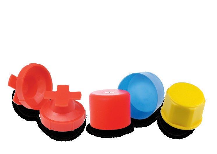
» VACUUM CUPS ARE available in a range of compounds, with each selected for specific application requirements. While many materials exist, four primary types are most used across industries. This article explores these materials in detail, pertinent to their performance, advantages, and the best use cases for each.
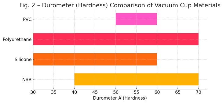
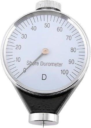
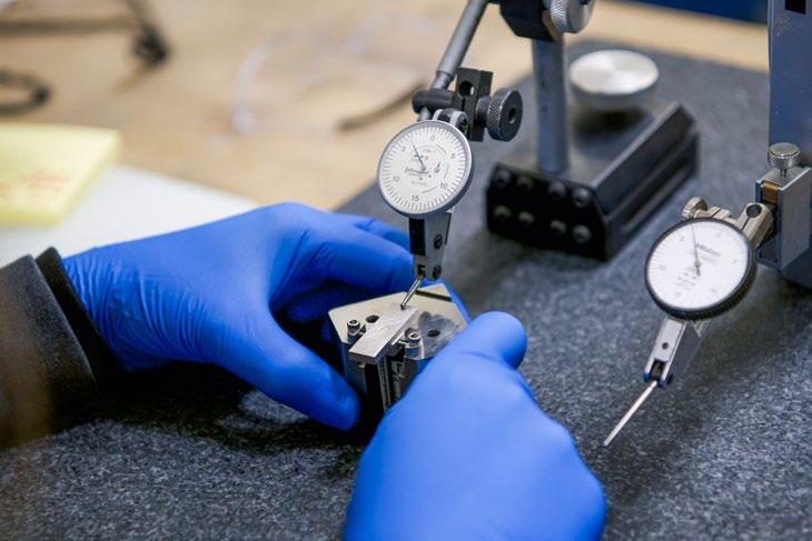
The starting point when selecting a vacuum cup material is typically its hardness, which determines its ability to form a reliable seal on a given surface. Hardness is measured using the Shore hardness scale, often referred to as the durometer scale (Fig. 1 shows a durometer hardness tester). It is named after its inventor, Albert Shore. The Durometer A scale (shown in Fig. 2) used for rubber-based materials ranges from 5 (very soft) to 100 (very hard). Most vacuum cups fall between 35 and 70 durometer A. Understanding this value is
key to ensuring that the cup seals effectively on surfaces ranging from smooth metals to rough cardboard.
Beyond hardness, temperature resistance plays a significant role in material selection. While most applications occur at ambient temperatures, some, such as plastic injection molding or frozen food packaging, require materials that can withstand extreme heat or cold.
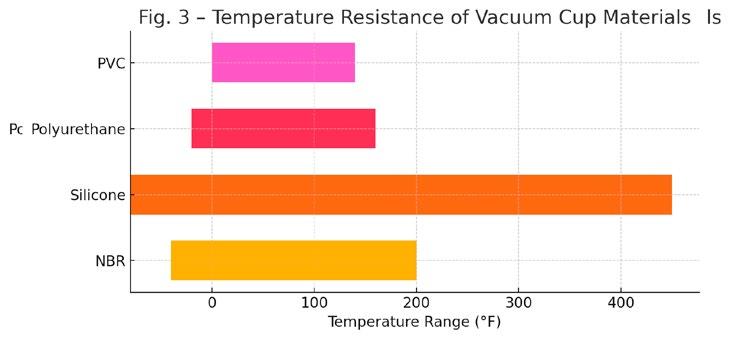
Vacuum cup compounds typically perform within a range of -40°C to 204°C (-40°F to 400°F). Refer to Fig. 3. However, it's essential to assess the actual temperature of the product being handled and not just the environment or mold. Overestimating temperature needs by adding unnecessary safety margins can lead to inflated costs. For example, a molded part leaving a 93°C (200°F) mold may cool rapidly, making it safe for handling with a material rated below that threshold, especially if contact is brief. Keep in mind that a vacuum reduces air molecule density, which can lower surface temperatures further during handling.
NBR, also known as Buna-N, is the most widely used vacuum cup material. It's highly resistant to oils, greases, and industrial chemicals, making it ideal for general-purpose applications such as metal, plastic, wood, and cardboard handling. NBR is typically 60 durometers but can range from 40 to 70 depending on the manufacturer.
NBR is often overlooked for high-heat applications due to the assumption that only silicone will suffice. However, many plastic injection parts can be safely handled with NBR if the part temperature remains within the material’s capability (around 93°C (200°F)). It provides superior abrasion resistance compared to silicone, making it a cost-effective and durable choice in many scenarios.
Silicone vacuum cups offer exceptional temperature resistance, handling both extremely cold and hot environments up to 230°C (450°F). This makes them suitable for use in frozen food packaging and hot molded plastic applications. Silicone is softer than NBR, allowing better sealing on contoured, uneven, or porous surfaces such as corrugated plastic or cardboard. Additionally, FDA-compliant silicone (FDA 21 CFR 177.2600) defines which rubber articles, including silicone, are safe for repeated contact with food. This is available for applications involving direct contact with food
or pharmaceuticals, ensuring there is no contamination from dyes or additives.
Metal-detectable silicone is widely used in food processing environments as an added safety measure to protect both consumers and manufacturers. In high-speed production lines handling baked goods, packaged foods, or pharmaceuticals, there is a risk that a partial or full vacuum cup may become dislodged and fall into the product stream.
By incorporating metal-detectable additives, e.g., iron dust, into the silicone compound, these cups can be easily detected by inline metal detection systems that are standard in most food manufacturing facilities. This allows for immediate identification and removal of any contaminated batches before packaging or distribution.
The benefit of this safety feature cannot be overstated. Foreign object contamination is one of the leading causes of damaged brand reputation and consumer injury. A single undetected vacuum cup fragment could trigger a costly full-scale recall, halting production and distribution while exposing the manufacturer to liability and regulatory scrutiny.
By using metal-detectable silicone, manufacturers demonstrate a proactive commitment to food safety and quality control. This significantly reduces the risk of recalls and complies with Hazard Analysis Critical Control Point (HACCP) and other global food safety standards. Note: Silicone should never be used on surfaces intended to be painted, e.g., automotive body panels. Contact with silicone can cause paint bonding issues known as fisheyes. As a result, many automotive plants prohibit its use entirely.
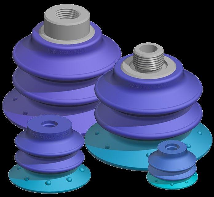
Polyurethane offers solid wear resistance, outperforming both NBR and silicone in abrasive applications. It's especially useful for high-speed or long-cycle production lines where cup longevity is critical. However, polyurethane generally offers a narrower temperature range, and its cost is higher than that of NBR. Some vacuum cup designs use a dual-durometer configuration (Fig. 4), a soft sealing lip combined with a rigid core. This balances seal flexibility with structural stability. With that being said, these dual-compound cups are labor-intensive to manufacture, which adds to their cost.
PVC vacuum cups offer a low-cost alternative with trade-offs. While they are highly resistant to abrasion, the mechanical properties of PVC are inferior to rubber-based materials. They are prone to hardening and cracking, especially in dynamic stress areas such as bellows corners. Their limited temperature range and durometer options further restrict their versatility. Though initially inexpensive, PVC cups may have higher long-term costs due to more frequent replacements. They serve as a low-cost solution for simple pickand-place applications.
Color alone cannot reliably indicate the cup compound. For example, NBR is usually black, silicone is often red or white, polyurethane comes in a variety of colors, and PVC is generally clear or lightly colored. To select the correct vacuum cup, start with the application, not the appearance. Consider the following: Does this application truly require silicone? Could a more economical compound like NBR be equally or more effective?
Choosing the right vacuum cup material depends on a solid understanding of the application, including surface type, temperature, wear conditions, and regulatory requirements. Assuming the existing material used in an application is correct isn’t ideal. It's always worth reassessing if a better-performing or more cost-effective option is available.

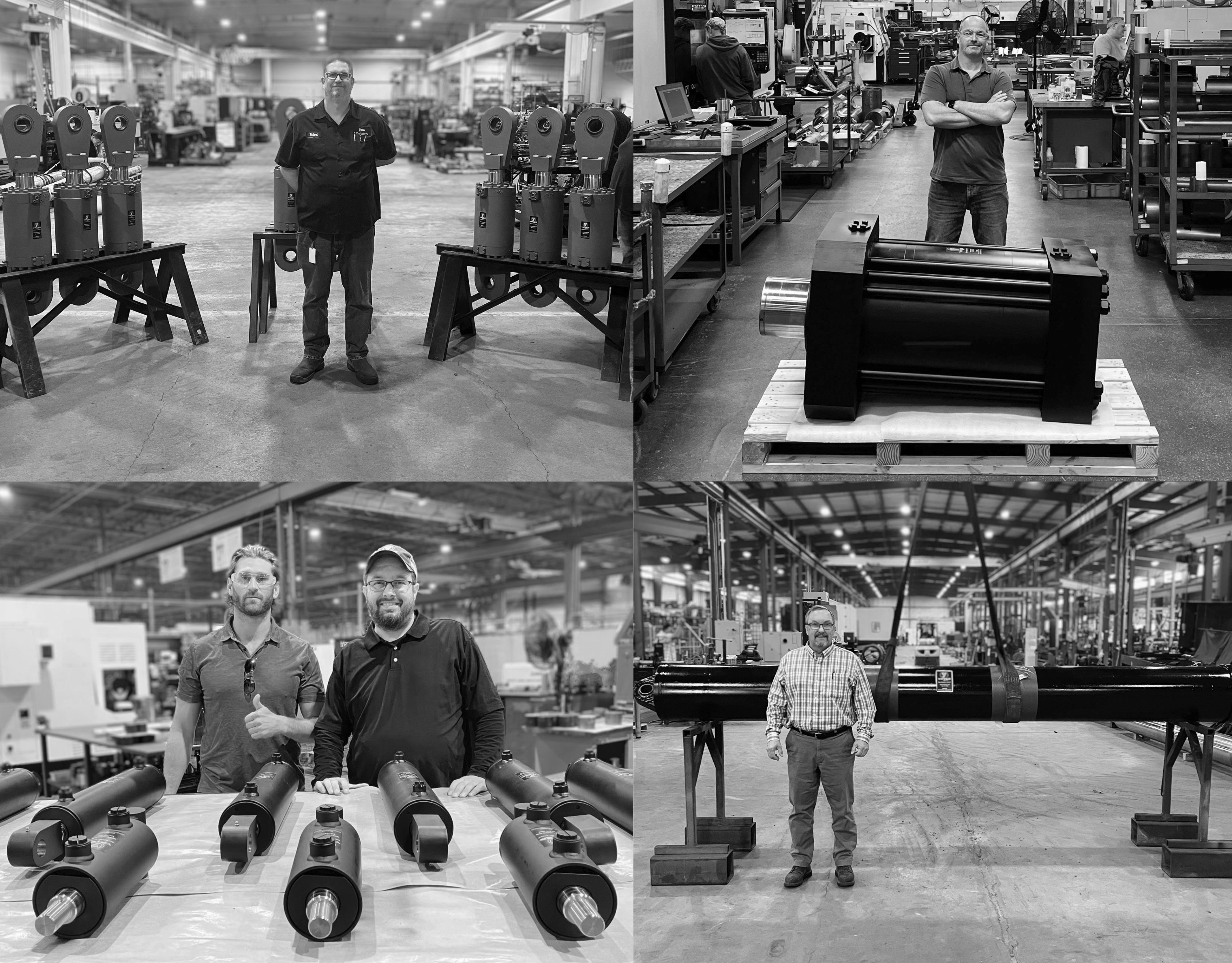
Yates Industries is a manufacturer and rebuilder of hydraulic and pneumatic cylinders of worldclass value. Established by William H. Yates II in 1972, Yates has evolved into a state-of-the-art family-owned company with over 365,000+ sq. ft. of manufacturing and repair space.
Yates Industries repairs all brands and designs. In addition to being a highly reputable cylinder repair company, we manufacture both pneumatic and hydraulic Tie Rod, Welded round body, and Mill-type cylinders for all demanding applications.
Going strong for over 50 years plus; Yates proudly serves all industries from Steel, Aluminum, Oil & Gas, Paper & Wood, Food, Defense and many more. The viable demand for Yates quality products and services continued to grow, prompting several expansions in Georgia, Alabama, and Ohio. Adding these facilities gave Yates greater capacity for our welded and mill duty cylinder lines; enabling us to provide faster turnaround times and increase our service area throughout the southern U.S. Yates strives to maintain our reputation as one of the largest most complete cylinder manufacturing companies in the country.
Contact us today to handle ALL your cylinder needs! Proudly made in the USA.
By Francesco Reino, Manager of Performance and Testing at Servotronics, Inc. and Francisco Tizón, Director of Marketing & Sales at Servotronics, Inc.

Few components have had as significant an impact in the vast and dynamic world of fluid power as the servo valve. While often overlooked as a small piece in a larger system, servo valves are indispensable in applications demanding high precision, reliability, and control. These applications range from aerospace to industrial automation and medical devices. Servo valves quietly power the systems we rely on daily. But what makes this technology so critical, and how has it evolved into the sophisticated, adaptable tool we see today?
Let's delve into the world of servo valves, exploring their anatomy, design intricacies, variations, and applications. Why do they remain at the forefront of fluid power control?
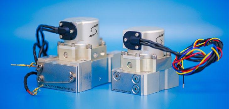
At its core, a servo valve is an electromechanical device capable of controlling the flow and pressure of a hydraulic or pneumatic fluid based on electrical input signals. These valves provide precise control over motion, positioning, or force, making them indispensable in applications requiring high accuracy, fast response, and repeatability. Servo valves typically come in two main designs:
1 Single-stage valves, whose package is generally smaller but capable of precise pressure control in low-tomedium flow applications.
2 Two-stage valves use a pilot stage to control a larger main stage, thus offering higher flow rates to handle greater loads.
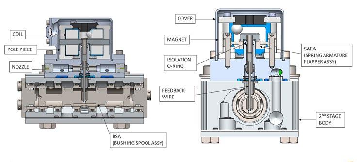
A torque motor is one of the servo valve's components. This converts electrical signals into mechanical motion using both permanent and electromagnetism. Key elements are permanent magnets, pole pieces, coils, an armature, a fluid seal, and a torsional or flexure tube 'spring'. The primary function of the torque motor is to provide accurate repeatable displacement of a flapper or jet.
In cases where a torque motor is used as the pilot stage for a 2-stage electro-hydraulic servo valve(EHSV), a feedback wire is affixed to the flapper or jet to provide mechanical feedback from the second stage's spool position. In an EHSV, the torque provided by the torque motor becomes the most critical characteristic.
At the pressure metering stage, the flapper nozzle or jet pipe topology is the most commonly used to provide precise fluid control. This stage varies based on the application. Four-way pressure control is typical in a 2-stage EHSV to provide delta (pilot) pressure to the mainstage spool type valve. However, in a single-stage application, the metered fluid directly interacts with the hydraulic or pneumatic system. Single-stage servo valves (SSSVs) can be implemented as two-way flow controls, three-way pressure controls, fourway pressure controls, and other iterations. Today's SSSVs have more power and flow capability than the small pilot valves traditionally associated with EHSVs.
Mainstage, known as the second stage of a 2-stage EHSV, is the flow amplifier. A main stage potentially mimics, to a certain extent, the behavior of its pilot stage. What is achieved
is significant amplification of the flow rate while maintaining low leakage values. A 4-way EHSV is the most common variety with rapid, precise response of large flow values to provide control over large piston diameter actuators. Today's EHSVs can include 3-way, antiskid braking architectures as well as multiple port and complex flow controllers. For example, multiple 2-way subsystems can be controlled with a single EHSV.
Each element must work in harmony, requiring meticulous design and assembly to achieve optimal performance.
Designing a servo valve is a delicate balance between art and science. Much like crafting a high-performance loudspeaker, the process


involves fine-tuning various parameters to achieve the desired performance. Key considerations include electromagnetic properties such as coil turns, wire gauges, precise air gaps, spring rates, and magnet strength. Mechanical precisions are also important in hydraulic components' spacing in the pilot or SSSV. Finally, hydraulic dynamics include orifice, nozzle/jet diameters, edge conditions, and porting strategies.
While mathematical modeling is essential, real-world testing and adjustments are almost always required to optimize performance. This iterative process highlights the need for patience, expertise, and a deep understanding of the physical interaction between the critical subcomponents.
The assembly of a servo valve demands exceptional precision. Components must be manufactured to tight tolerances and assembled with meticulous care in
continued on page 26


contamination-controlled environments. Steps in the assembly process include:
1 Torque Motor Assembly: This ensures proper alignment and electrical connectivity.
2 Hydraulic or Pneumatic Section Integration: This involves matching orifice sizes and flow paths.
3 Calibration: This involves fine-tuning the valve to meet specific performance criteria.
Consistency is paramount. Even the slightest deviation in assembly can lead to performance variations. This is why experienced technicians follow rigorous procedures and quality checks.
Servo valves have their place in diverse sectors, each with unique demands. In aerospace this includes controlling flight surfaces, landing gear, fuel delivery, environmental controls, and braking systems with unmatched precision. Almost any actuator on an airframe may be controlled with either an EHSV or SSSV. In the area of industrial automation, servo values can be used to manage robotic arms, conveyor systems, actuator control, as well as pressures and flows to ensure high-speed, accurate operations.
In the medical device field, servo valves ensure precise movements in surgical devices or flow control. Typical applications include ventilators and surgical cataract removal equipment. Pertinent to the energy sector, servo valves regulate flow and pressure in turbines, drill strings, actuation, and subsea systems in oil and gas operations. Their adaptability to both hydraulic and pneumatic systems further broadens their applicability, making servo valves a cornerstone of modern engineering.
As with any technology, servo valves face obstacles. Peak performance requires ongoing innovation to address electromagnetic
efficiency, developing materials and designs to reduce energy consumption and package size. Miniaturization is achieved by creating compact valves for space-constrained applications with high-pressure capability. Enhancing resistance to wear, vibration, temperature, and environmental factors is crucial to maintaining durability.
Recent advancements include integrating digital control electronics, allowing for more precise and customizable operation. Smart servo valves now feature self-diagnostic capabilities. Remote adjustment of pressure and flow gain paves the way for predictive maintenance and improved system reliability.
Despite the emergence of alternative technologies, servo valves remain a preferred choice in many applications. Their advantages include accuracy and speed, delivering precise control with consistent performance over time. Valves' versatility and power density specific to modern single and 2-stage servo valves can provide functionality and capability beyond what is typically considered.
Furthermore, their ability to handle extreme conditions including high pressures, temperatures, and demanding duty cycles makes servo valves indispensable in mission-critical environments. For specialized scenarios, such as those involving high temperatures or significant vibration, custom solutions that extend the limits of servo valve performance ensure reliability even in the most challenging environments. As industries continue to demand more from their fluid power systems, the importance of servo valve technology remains undiminished, with innovations continually reinforcing its position as a cornerstone of precision control.
For those interested in servo valve manufacturing or maintenance, a strong foundation in physics, electrical fundamentals, and mathematics is beneficial. However, the true mastery lies in hands-on experience and the discipline to follow meticulous procedures. As one technician aptly put it, "Consistency is key. The art of servo valves lies in designing and dialing them into the sweet spot where they meet application-specific needs." In addition, valuable technical references can be found in
the Aerospace Recommended Practices (ARPs), which are published by the Society of Automotive Engineers (SAE). The ARP490G contains a wealth of information, ranging from definitions to standards for mounting interfaces, and physical performance and testing of servo valves.
Looking ahead, servo valves are poised to continue playing a pivotal role in key industries such as aerospace, defense, energy, and industrial applications. Innovations in materials, manufacturing techniques, and digital integration will further enhance their performance and expand their capabilities. Servo valves may be small components, but their impact on fluid power systems is immense.
From precision control in aerospace to rugged durability in industrial applications, servo valves embody the perfect blend of engineering and craftsmanship to provide a variety of solutions. Understanding their design, assembly, and applications underscores their critical role in advancing technology across industries. As fluid power continues to evolve, servo valves will remain at the forefront, driving innovation and enabling solutions that power the world. Whether you're an engineer, technician, or industry enthusiast, appreciating the intricacies of servo valves offers valuable insights into the heart of modern machinery. Key takeaways include:
1 Servo valves control fluid flow and pressure with unmatched precision and reliability.
2 These valves consist of torque motors (which are the electromagnetic portion), as well as hydraulic or pneumatic sections.
3 Applications span aerospace, defense, industrial automation, medical devices, and energy.
4 Innovations like miniaturization and increased capability of smaller single and 2-stage servo valves are shaping their future.
5 Mastering servo valve technology requires both technical knowledge and hands-on expertise. By understanding and leveraging the capabilities of servo valves, the fluid power industry can continue to meet the challenges of tomorrow.•
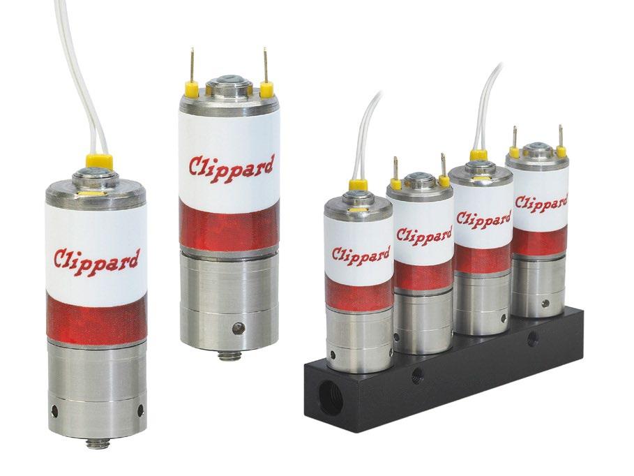
Clippard’s DVP Series proportional solenoid valves are precision-built 2-way control valves, utilizing a unique, patented valving principle. They offer an extremely high cycle life, fast response, linear flow gain, low hysteresis, low power consumption, and flows over 60 l/min. The valve provides air or gas flow control, and varies the output flow based on the current input to the solenoid. Proudly made in the USA.

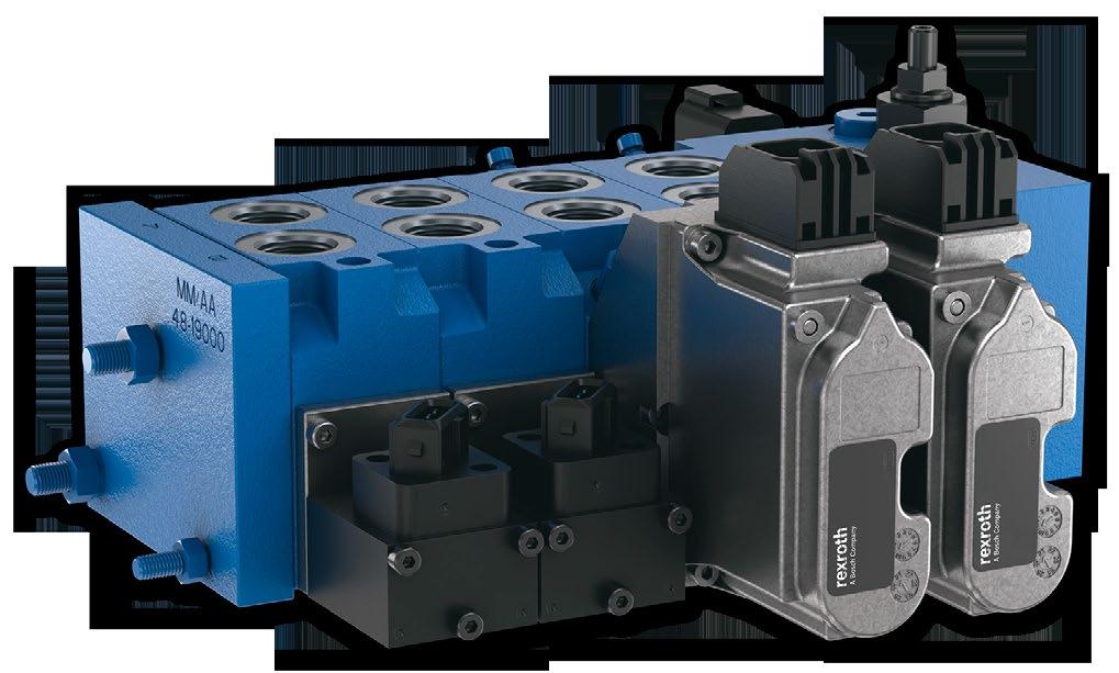
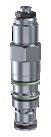
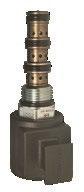
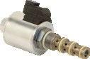
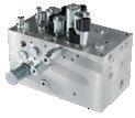
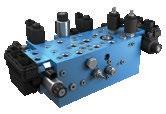
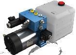
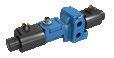
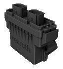
Boost performance with modular compact directional valve (CDV) technology from Bosch Rexroth. Featuring on-board electronics, EDG Compact Directional Valves provide complete communication between sensors and hydraulic components. Available for a wide range of applications including mobile elevated working platforms, truck-mounted cranes, compact construction equipment and agricultural machinery.

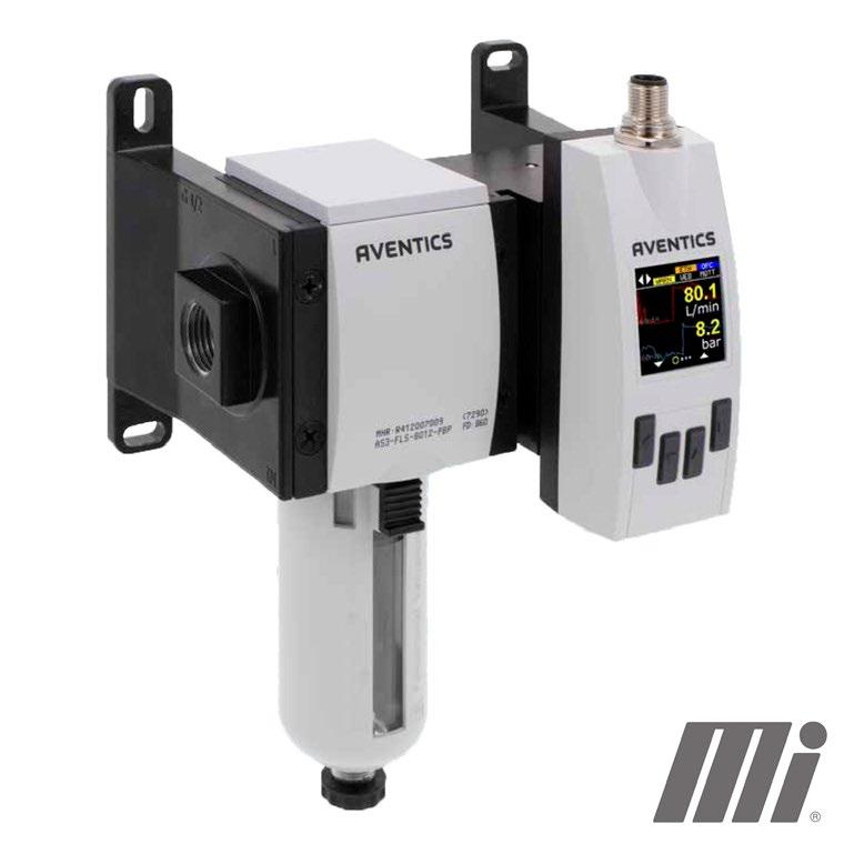
AVENTICS Series AF2 – Available from Motion AVENTICS Series AF2 flow sensors monitor air consumption in pneumatic systems, enabling rapid intervention in the event of leakage. The Series AF2 helps to optimize energy consumption, prevent machine downtime and cut costs. Both the in-line piped version and modular filter version with American National Standard Taper Pipe Thread (NPT) are available in the Americas.
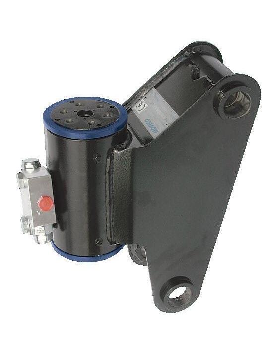
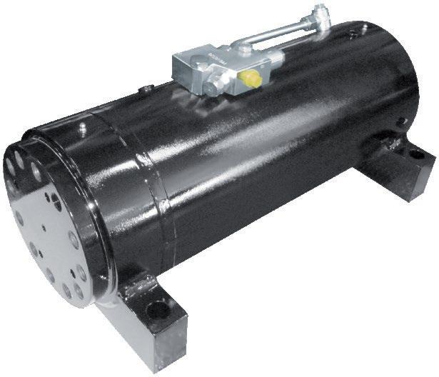
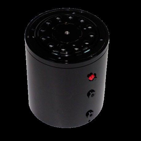
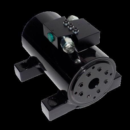
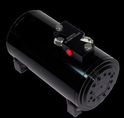
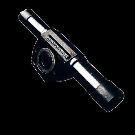
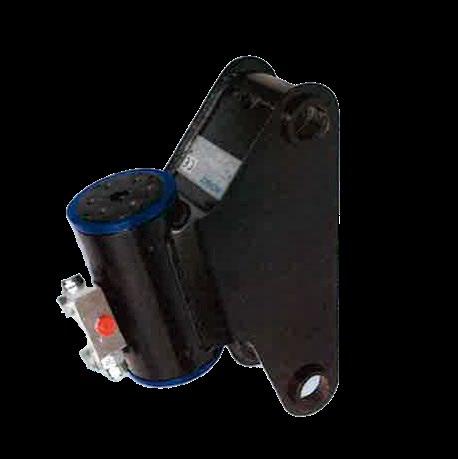
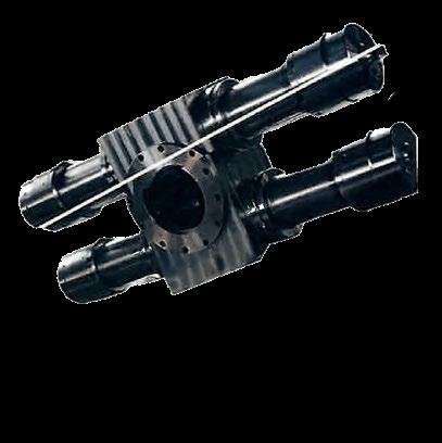
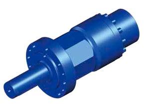
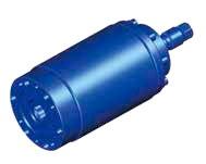
Young Powertech, Italian made Helical Hydraulic Rotary Actuators cover a wide range from 45 to 40,000 LB-FT torque and up to 750 degrees rotation for mobile and industrial applications. Local inventory for quick delivery and service and worldwide support makes it the best option for your rotating applications.

3060 Plaza Dr. #108
Garnet Valley, PA 19060
Telephone: 610-558-0760
Email: info@youngpowertech.com www.youngpowertech.com delivers solutions
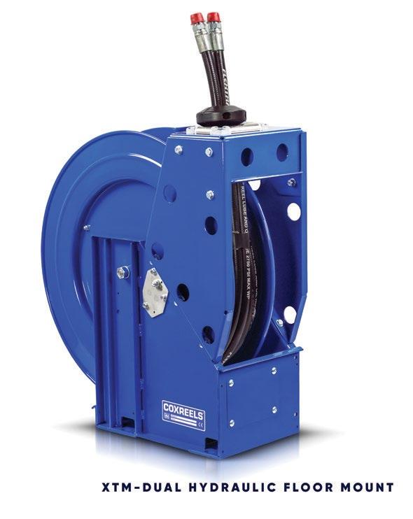
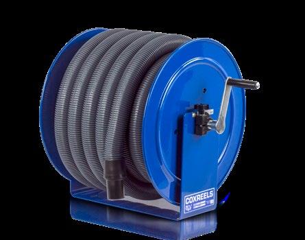
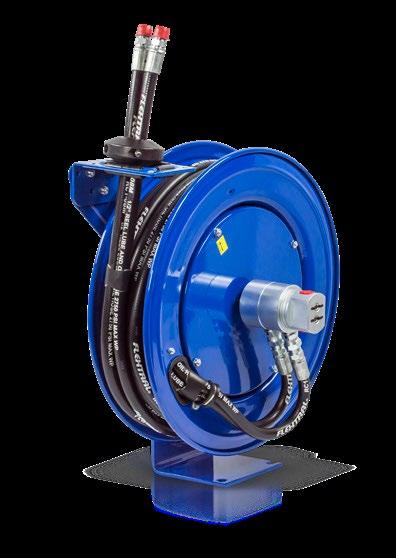
Coxreels® Extreme Duty
XTM Dual Hydraulic Reel! XTM-DMP-450 is the most robust reel with triple axle support, twin-line fully bonded hose, and stainless-steel hose guide rollers. As with all Coxreels reels, it features heavy gauge steel construction, durable CPC powder coat, rolled and ribbed discs, and USA made. www.coxreels.com
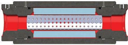
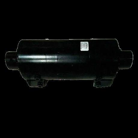
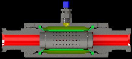
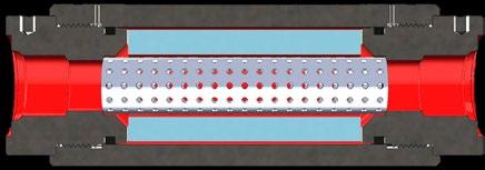
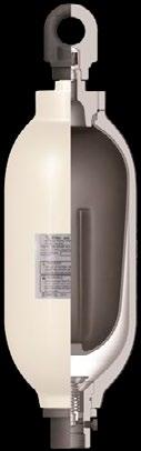
Wilkes and McLean manufactures an In Line Noise and Shock Suppressor for hydraulics and is a stocking distributor of Nacol Accumulators. Our suppressors eliminate pulsations, which greatly reduces noise and vibration from applications from a few gallons up to 200 gallons. We stock all of our suppressor sizes as well as Nacol Accumulators and parts from 1/5 of a pint up to 15 gallons, in our Schaumburg, Illinois facility. 877.534.6445 | info@wilkesandmclean.com | www.wilkesandmclean.com

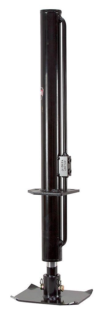
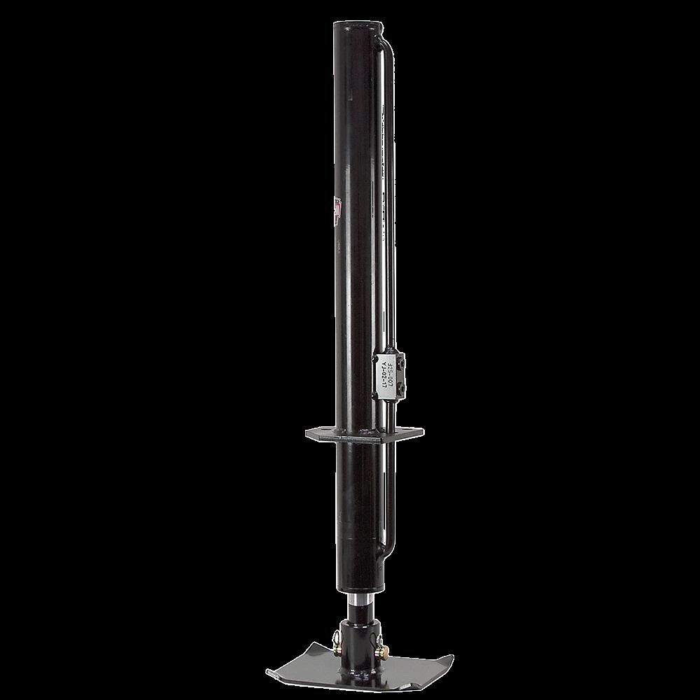
Our Stilwell hydraulically powered trailer tongue jacks are now on sale for $59.95. Works with bumper hitch trailers, trash trailers, and equipment trailers. Able to lift up to 7000 pounds with a max pressure of 3200 PSI. Simple installation using existing jack mounting holes on trailer tongue. Learn more at surpluscenter.com
surpluscenter.com (800)488-3407


Diamond Hydraulics Inc.
Diamond Hydraulics is a veteran owned small business that manufactures, rebuilds, and repairs hydraulic equipment including cylinders, pumps, motors, valves, power units, and much more. We were established in 1999, and have over five decades of experience in hydraulic equipment repair.
Diamond Hydraulics provides quality workmanship, extensive industry knowledge, and fast turnaround time on repairs and replacements. All repairs are brought back up to OEM standards and tested with state-of-the-art test equipment.
Diamond Hydraulics Inc. 409-986-3957 (Office) 409-986-7437 (Fax) sales@diamondhydraulicsinc.com
» HERE IS THE SOLUTION TO FIGURE IT OUT ON PAGE 05
When CFC Industrial Training was asked to help, they realized that this pilot-operated valve required slight backpressure to operate properly. For troubleshooting, they installed a manually adjusted flow control after the proportional valve. This provided back pressure and was not intended to control volume; it dampened the pulsing and eventually eliminated it. So, why didn’t the motor’s load provide this back pressure? It turns out that, because the machine’s gears had such a high gear reduction, and the rebuild

Enhance workplace productivity and eliminate trip hazards with the Upright 3 Hose Reel Assembly (TH7-8). This heavy-duty unit keeps hoses neatly stored and off the floor, creating a cleaner, safer, and more efficient environment. Other hose storage solutions available. Distributor opportunities available— contact Jeff Lewis at jlewis@ safetystep.net or 540-362-9636 Learn more at www.hosefabworkstations.com
had just replaced all the bearings, there was little resistance, and any time the motor was started, it over-spun and caused cavitation. The cavitation caused the proportional throttling valve to close. As the downstream flow slowed drastically or stopped, the valve would open again. This on-off was repeating, causing the pulsing. The manual throttle was removed, and the problem was corrected using a 207 kPa (30-psi) backpressure check installed on the tank line of the directional valve.
The correct answer to Test Your Skills on page 12 is 1D.

By Skyler Libkie, Technical Writer, SUCO ESI North America
Vehicle reliability and performance are not only desirable but essential in the world of military operations. Each component must perform flawlessly in extreme conditions. Hydraulic and engine systems are critical to operational readiness, as they rely heavily on accurate monitoring. To that end, tachometers and pressure transducers are essential within the military industry.
Military vehicles such as the ubiquitous High Mobility Multipurpose Wheeled Vehicle (Humvee) operate in hostile and diverse environments. Its internal systems are subjected to extreme stress in harsh environments, from scorching deserts and freezing tundra. It is vital to monitor key operational parameters for safety, mission effectiveness, and preventative upkeep.
Pressure monitoring is a great way to detect leaks or blockages early and prevent mission-critical failures. Transducers are essential components that convert pressure into an electric signal. They are constant monitors in the hydraulic systems of military vehicles. The role of these transducers includes:
• Monitor engine operation including fuel pressure, oil pressure, and coolant pressure to ensure that the engine is running optimally and preventing catastrophic failures.
• Track transmission performance, including hydraulic pressure, to ensure smooth gear changes and long-term durability.
• Use pressure transducers in advanced hydraulic or hydropneumatic systems to maintain vehicle stability and ride height; also helps handle characteristics when the vehicle is under heavy load or rough terrain.
• Leverage power steering systems to ensure adequate hydraulic pressure for vehicle maneuverability.
• Monitor the pressure in hydraulic brake circuits to ensure safety and responsiveness.
• Monitor the pressure in hydraulic systems that operate winches, ramps, or other specialized equipment and accessories.
Tachometers measure rotational speeds (RPM, revolutions per minute). Their applications in military vehicles are varied and essential for performance optimization and diagnosis. Some factors to consider include:
• RPM monitoring provides the driver with vital information about engine performance, which helps to maintain optimal power bands and avoid overrevving.
• Monitoring hydraulic pump speed ensures that they are working efficiently and providing the flow rate required for different systems, with deviates indicating fluid or pump problems.
• Tracking rotational speeds of other critical components, such as cooling fans, alternators, or auxiliary power units (APU), ensures they work correctly.
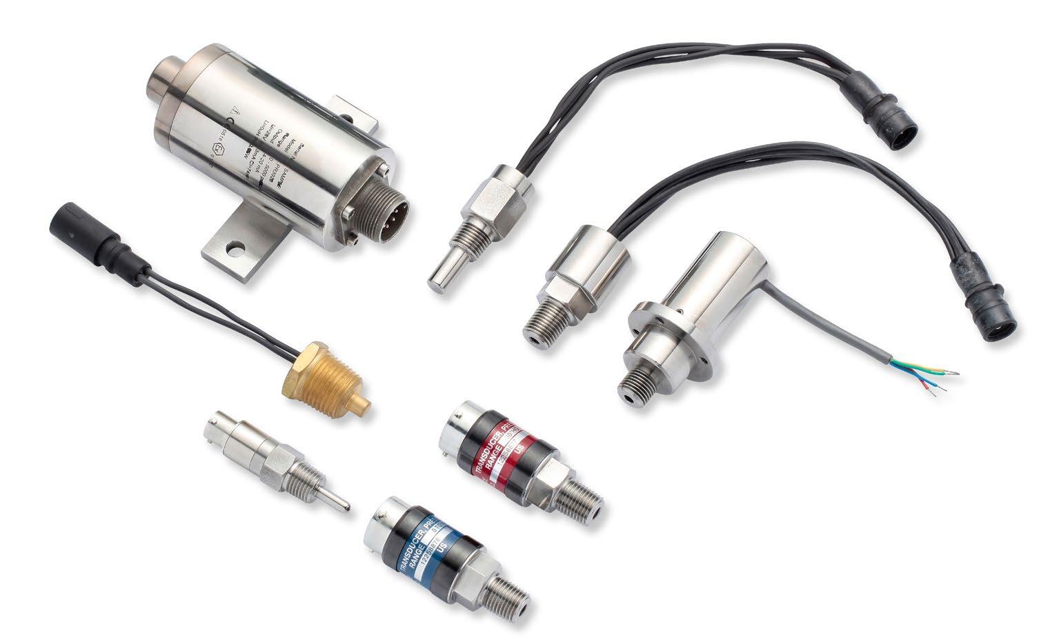
Tachometers are essential to maintaining operational efficiency. They can also be used to diagnose potential problems before they become serious.
Sensors purchased off-the-shelf are not always suitable for military applications. Components for Humvees or other tactical platforms are subject to strict criteria. These include:
• Ruggedness and Durability: Ability to withstand extreme temperatures, along with high levels of shock and vibrations, moisture ingress, and exposure to harsh chemicals (fuel, oils, hydraulic fluids) is key.
• Accuracy and Reliability: For safety and performance, it is essential to have precise and consistent measurements.
• MIL Spec Compliance with Military Standards: This ensures interoperability and reliability under specified conditions.
• NSN Accessibility: National stock numbers simplify procurement and logistics in military organizations and defense contractors.
Companies exist that are exclusively dedicated to manufacturing high-quality pressure transducers and tachometers tailored for the military sector. Many product offerings are expertly engineered to meet the rigorous demands of military operations.
Pressure transmitters and transducers are designed to endure the extreme physical stresses encountered during military deployment, often featuring stainless steel housings and resilient sensing components. These sensors deliver reliable, high-accuracy data for vehicle systems and maintain stability over time. Similarly, tachometers are crafted for precision and durability, enabling them to accurately measure speed under any conditions.
Understanding that standard products may not meet every requirement, there are customization options that can be leveraged to adapt to specific platforms and applications. In military vehicles, failure is not an option. The reliability of each component, including pressure transducers and tachometers, directly affects mission success and safety. •
By John Narup, Applications Engineer, Festo


Lowering compressed air consumption in a pneumatic system is not immediately considered a powerful means of boosting machine performance and longevity. However, it allows for lighter and smaller footprint machines and control panels. These are features vital to end users. The following energy reduction tips offer the highest savings and performance increases. They are gleaned from a 30-year career in applications engineering.
Vacuum gripping is a mainstay of 6-axis robots in palletizing cells. In these large cells, pumps have been widely applied to create a vacuum. With the rise in using collaborative robots and the growing need for bin-picking solutions at distribution centers, vacuum gripping is on the rise. It is widely applied on end-of-line packaging machines and processes.
Specifying, installing, and maintaining a vacuum pump for every robot or packaging machine application does not make good sense in terms of cost, installation, and footprint. The alternative to vacuum pumps is venturi vacuum generators. Venturi
generators use compressed air to generate a vacuum. They are small, lightweight, and ideal for end-of-arm tools. The lighter the tool, the faster, smaller, and less costly the robot is. The problem with venturi vacuum generation is that venturis run constantly and consume large amounts of compressed air.
The solution is purchasing a vacuum generator with a built-in energy savings circuit. A vacuum sensor monitors the vacuum level turns off the air when a set point is reached and switches on again when the vacuum falls to a reengage point. An energy savings circuit on a venturi system can reduce energy usage by up to 60% in comparison to the one without the circuit. There are online Festo engineering tools available to specify right-sized systems by simply entering application parameters.
Piezoelectric-based proportional control valves, both fast and quiet, can save up to 50% of the energy of a proportional solenoid valve. These valves are also lightweight, durable, and small in size. The valves fall under the overall umbrella of controlled pneumatics solutions, including:
• Proportional pressure regulation in high and low flow rates
• Multi-channel control of large or small workpieces
• Ultra-compact proportional control valve manifolds
• Proportional control valves
• Compact mass flow controllers for inert gases.
An example of this is the VTEM motion terminal, introduced in 2017 as an innovative piezoelectric-based valve terminal for pneumatic automation. This preceded the launch of piezo-based proportional control components for a range of solutions.
The world’s first proportional valve manifold, the Festo VTEP, provides closed-loop control of moderate airflow on up to 10 channels. The VTEP is ultra-compact, measuring less than five inches wide.
The core element of piezoelectric valves is the piezo ceramics. When the ceramics are electrically charged, it creates polarization that causes the ceramic material to bend. The bending is proportional to the applied voltage and enables the flow rate or pressure to be regulated proportionally. The higher the voltage, the greater the flow rate. A piezo valve

GET. KEEP CUSTOMERS.
» PLACE YOUR MESSAGE in the inbox of thousands of potential new customers that directly mirror your best prospects. Customize your audience by zip code, county, state, age, gender, income, personal interests and almost limitless characteristics! CONTACT US FOR RATES 3245 Freemansburg Ave, Palmer PA 18045
Phone: 800.730.5904, 610.923.0380 | Fax: 610.923.0390 www.fluidpowerjournal.com
does not need to be constantly energized since it behaves like a capacitor. An initial current is needed to charge the ceramic material once; from there, the current consumption drops to practically zero.

The Festo VEMP piezoelectric valve’s ceramic lifters enable proportional control and create 50% energy reduction compared to solenoid valves.
A Nitrogen gas (N2) purge application at a silicon wafer manufacturing plant provides an example of the capability of this new
continued on page 34


continued from page 33
type of fast-acting valve that saves energy and improves operations. The controlled pneumatics VEAD proportional control valve cuts the N2 flow rate for oxygen flushing by 75%. For every 1,000 nitrogen purge systems, the plant saved $163,000 in energy costs. The reduced energy lowered CO2 emissions from energy generation by 1,045 metric tons. In other words, controlled pneumatics removed CO2 emissions, the equivalent of burning 1.2 million pounds of coal.
When designing a pneumatic automation system, it’s natural to oversize components to ensure performance. Components that are larger than needed indicate maximum air consumption, as well as higher friction and heat. They’re also indicative of greater vibration, larger footprint, more weight, and additional costs.

The simulator presents three options for the designer:
• The exact solution, a perfect match for the entered parameters
• An economical variant that consumes less air but has a slower positioning time
• A performance variant that uses more air but gives the cylinder a significant speed boost.
The tool identifies the correct accessories, including tubing, fittings, and valves for each option, saving specification time. Using the options of exact match, eco, and performance, designers can aggregate components into a system that offers the utmost performance with optimum air consumption. In other words, a mix-and-match of machine components for various performance requirements is the “right sized” pneumatic system.
to think flexibly and creatively about optimal pressure for the machine, individual valves, and valve manifolds. Reducing pressure without diminishing performance can lower energy consumption by up to 22%.
Another effective method to decrease air consumption is to reduce pressure on the return stroke of a cylinder. For example, from 6 to 3 bars. Reducing return stroke pressure makes sense because no work is done on the return stroke. The machine consumes less energy with every cycle.
End users demand smaller footprint solutions, lighter components, and ways to improve price and performance. A benefit of this new generation of machines is decreased energy consumption. Rather than oversizing, right-sizing pneumatic components is the best choice. It’s estimated that right-sizing versus oversizing can reduce total air consumption on the machine by up to 35% while offering all the advantages of smaller, lighter machines and control panels. Right-sized machines wear longer, vibrate less, and cut costs due to lighter components. Additionally, reducing weight in pneumatic cylinders can contribute up to 18% in energy savings as compared to heavier components.
A free online pneumatic simulation engineering tool allows designers to enter basic application information, including moving mass, positioning time, required stroke, and mounting angle. If needed, such advanced feature parameters include additional thrust and friction, along with direction of movement and pressure and tubing length.
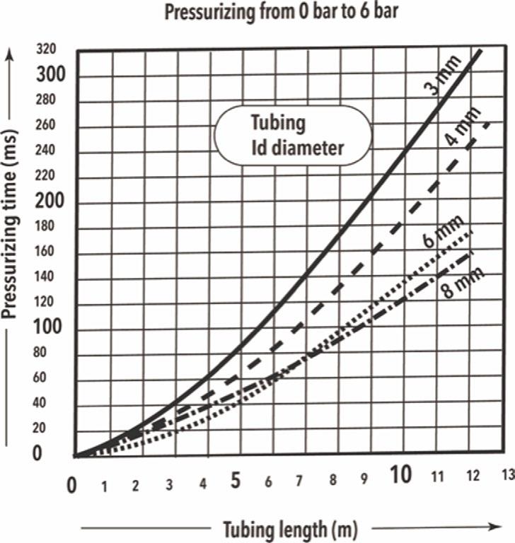
Right-sizing also minimizes the length of tubing between the valve and cylinder. It’s estimated that reducing tubing length can reduce energy consumption by up to 25% versus refraining from shortening the tubing. The closer the valve is to the cylinder, the higher the response speed and the lower the energy consumption. The new generation of more compact and higher-functioning valve manifolds, paired with advancements in remote and decentralized I/O, makes placing the valves closer to the cylinders in a distributed arrangement practical.
One of the parameters that can be entered into the pneumatic simulation tool is air pressure. Designers can enter from 2 to 10 bars into the tool and find various solutions. Optimizing pressure encourages designers
Designers seeking to improve performance and lower energy consumption must look for ways to substitute heavier materials for lighter ones. For example, using a polymer for a push plate rather than metal. Or, if metal must be used, drilling holes to lower the weight is advised. Reducing weight has the potential to lower energy consumption by up to 18%, as stated earlier in this article. Lowering friction by using components with ball bearings in place of frictional bearings, along with using lighter-weight pistons and better lubricants, can reduce energy consumption by up to 15%. Selecting components with higher-performing seals and fittings to lower the risk of leakage can create up to a 20% energy usage reduction by minimizing leaks.
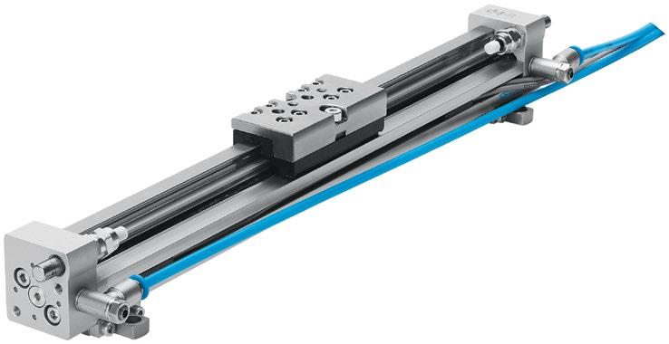
It is to the OEM’s advantage to invite vendors that emphasize consultation into a project as early as possible. This allows the vendor to introduce the OEM’s team to the latest component developments and a range of potential solutions. The savings in time and lower engineering overhead, particularly in the case of application engineering assistance, can have a profoundly positive impact on outcomes.•


almomanifold.com


Almo Manifold
989-984-0800
almomanifold.com
1-513-874-3225 cfcindustrialtraining.com
clippard.com
continentalhydraulics.com
COXREELS 25, 28 1-800-269-7335 coxreels.com
Diamond Hydraulics 3, 29 409-986-3957 diamondhydraulics.com
Essentra Components
1-800-847-0486 essentracomponents.com
FluiDyne Fluid Power 35 586-296-7200 fluidynefp.com
Gemels North America 7, 28 gemels.com
Harvard Corporation 21 608-882-6330 harvardcorp.com/filters High


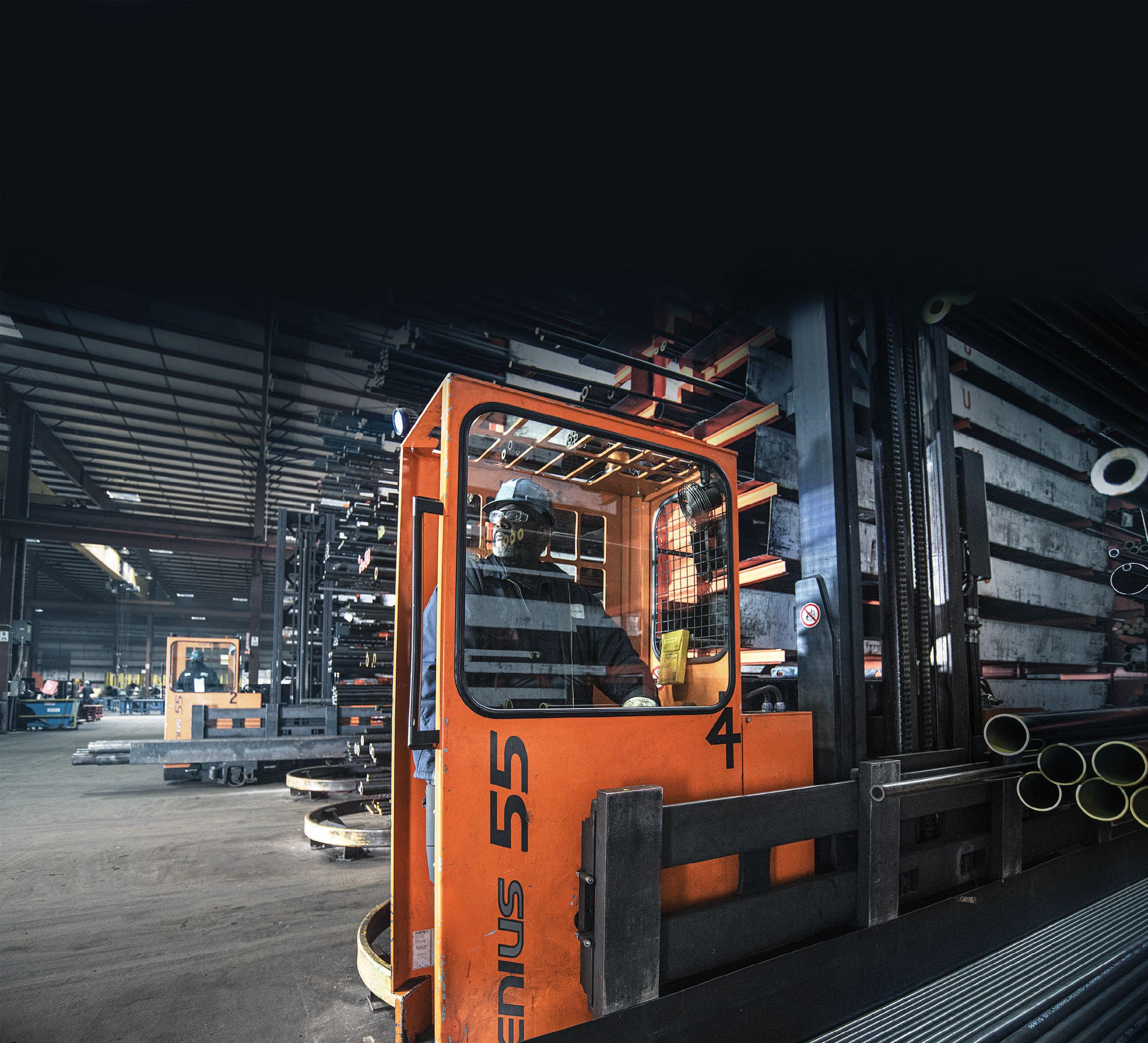
National Tube Supply’s fluid power products are precisely manufactured and expertly finished to minimize leakage and ensure longer seal life and optimum performance.
Our experienced team is always available to help customers identify the best product for their project specifications, quality requirements and bottom line. We’ll even work with you to set forecasts for JIT delivery management!
Hydraulic Fluid Line Tubing
Cylinder Barrels
Pneumatic Cylinder Tubing
Pump Barrels
Honed Steel Tubing
Chrome ID Tubing
Chrome OD Tubing
DOM Tubing
Seamless Steel Tubing
Chrome Plated Piston Rods
1045 Steel
Ductile Iron & Alloy
We have a massive inventory at your disposal with 8 locations across North America – most orders ship next day!
The Right Supply, Right On Time.