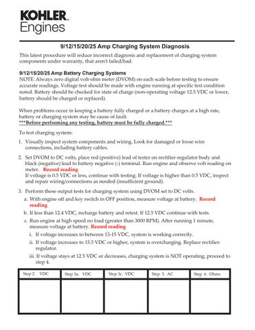
9/12/15/20/25 Amp Charging System Diagnosis This latest procedure will reduce incorrect diagnosis and replacement of charging system components under warranty, that aren't failed/bad. 9/12/15/20/25 Amp Battery Charging Systems NOTE: Always zero digital volt-ohm meter (DVOM) on each scale before testing to ensure accurate readings. Voltage test should be made with engine running at specific test condition noted. Battery should be checked for state of charge (non-operating voltage 12.5 VDC or lower, battery should be charged or replaced). When problems occur in keeping a battery fully charged or a battery charges at a high rate, battery or charging system may be cause of fault. ***Before performing any testing, battery must be fully charged.*** To test charging system: 1. Visually inspect system components and wiring. Look for damaged or loose wire connections, including battery cables. 2. Set DVOM to DC volts, place red (positive) lead of tester on rectifier-regulator body and black (negative) lead to battery negative (-) terminal. Run engine and observe volt reading on meter. Record reading If voltage is 0.5 VDC or less, continue with testing. If voltage is higher than 0.5 VDC, inspect and repair wiring/connections as needed (insufficient ground). 3. Perform these output tests for charging system using DVOM set to DC volts. a. With engine off and key switch in OFF position, measure voltage at battery. Record reading b. If less than 12.4 VDC, recharge battery and retest. If 12.5 VDC continue with tests. c. Run engine at high speed no load (greater than 3000 RPM). After running 1 minute, measure voltage at battery. Record reading i. If voltage increases to between 13-15 VDC, system is working correctly. ii. If voltage increases to 15.5 VDC or higher, system is overcharging. Replace rectifierregulator. iii. If voltage stays at 12.5 VDC or decreases, charging system is NOT operating, proceed to step 4. Step 2.
VDC
Step 3a. VDC
Step 3c. VDC
Step 5. AC
Step 6. Ohms