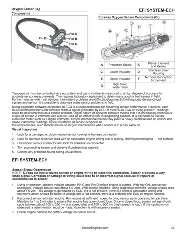
Oxygen Sensor (O2) Components
EFI SYSTEM-ECH Cutaway Oxygen Sensor Components (O2) G
D E
Pin D
C
A
Pin A
F
B
Pin B Pin C
A
Protection Shield
B
C
Lower Insulator
D
E
Upper Insulator
F
G
High Temp Water Seal
Planar Element and Heater Stainless Steel Housing Terminal Connection to Element
Temperature must be controlled very accurately and gas constituents measured to a high degree of accuracy for absolute sensor measurements. This requires laboratory equipment to determine a good or bad sensor in field. Furthermore, as with most devices, intermittent problems are difficulttodiagnose.Still,withagoodunderstandingof system and sensor, it is possible to diagnose many sensor problems in field. Using diagnostic software connected to ECU is a useful technique for observing sensor performance. However, user must understand that such software reads a signal generated by ECU. If there is an ECU or wiring problem, readings could be misinterpreted as a sensor problem. Digital nature of signal to software means that it is not reading continuous output of sensor. A voltmeter can also be used as an effective tool in diagnosing sensors. It is advisable to use an electronic meter such as a digital voltmeter. Simple mechanical meters may place a heavy electrical load on sensor and cause inaccurate readings. Since resistance of sensor is highest at low temperatures, such meters will cause largest inaccuracies when sensor is in a cool exhaust. Visual Inspection 1. 2. 3. 4. 5.
Look for a damaged or disconnected sensor-to-engine harness connection. Look for damage to sensor lead wire or associated engine wiring due to cutting, chaffingormeltingona Disconnect sensor connector and look for corrosion in connector. Try reconnecting sensor and observe if problem has cleared. Correct any problems found during visual check.
hot surface.
EFI SYSTEM-ECH Sensor Signal Observation NOTE: Do not cut into or pierce sensor or engine wiring to make this connection. Sensor produces a very small signal. Corrosion or damage to wiring could lead to an incorrect signal because of repairs or contamination to sensor. 1. Using a voltmeter, observe voltage between Pin C and Pin D before engine is started. With key ON, and sensor unplugged, voltage should read about 5.0 volts. With sensor attached, using diagnostic software, voltage should read about 1.0 volt. This voltage is generated by ECU. If it is not present, there is a short in associated wiring and corrective action should be taken. If voltage still is not present, there is a problem with ECU or engine harness. 2. Reconnect sensor and start engine. Run engine at sufficient speed to bring sensor up to operating temperature. Maintain for 1 to 2 minutes to ensure that engine has gone closed loop. Once in closed loop, sensor voltage should cycle between about 100 to 250 mv (low speed idle) and 700 to 900 mv (high speed no load). If this cycling is not observed, a determination must be made, if problem is with engine or sensor. 3. Check engine harness for battery voltage on heater circuit.
KohlerEngines.com
43