
Design Manual
Barrier Free Access 2008
Division
1 AUDITORIUM AND RELATED FACILITIES 11 Division 2 HOTELS, HOSTELS AND GUESTHOUSES 15 Division 3 CARPARKS 17 Division 4 ACCESS ROUTE 22 Division 5 RAMPS 27 Division 6 DROPPED KERBS 31 Division 7 STEPS AND STAIRCASES 36 Division 8 HANDRAILS 41 Division 9 CORRIDORS, LOBBIES AND PATHS 47 Division 10 DOORS 55 Division 11 TOILETS AND W.C. CUBICLES 60 Division 12 BATHROOMS AND SHOWER COMPARTMENTS 69 Division 13 SIGNS 73 Division 14 SPECIAL OBLIGATORY DESIGN REQUIREMENTS TO ASSIST PERSONS WITH VISUAL/HEARING IMPAIRMENT TO VARIOUS USES OF BUILDINGS IN TABLE 2 77 **ThenumberingsysteminChapters3and4correspondsasfaraspracticabletotheThird ScheduleofBuilding(Planning)Regulations.
CONTENTS Page PREFACE 1 Chapter 1 FOREWORD 2 Chapter 2 EXTENT OF APPLICATION 2.1 EXTENT OF APPLICATION 2.2 EXEMPTIONS 84 Chapter 3** PRELIMINARY 9 Chapter 4** DESIGN REQUIREMENTS
Chapter DESIGN GUIDELINES FOR
Page
Division
Appendix
Division
15 PUBLIC INFORMATION OR SERVICE COUNTERS 84 Division 16 ILLUMINATION 87
5.1 SWITCHES AND CONTROLS 5.2 FIRE ALARM SYSTEMS 5.3 PUBLIC TELEPHONES 5.4 REMOTE SIGNAGE SYSTEMS 5.5 VERTICAL LIFTING PLATFORMS 5.6 DRINKING FOUNTAINS 109106104112113116
THE ELDERLY AND ELDERLY WITH FRAILTY 119
6
20 ESCALATORS AND PASSENGER CONVEYORS 102
Appendix
C – Slip Resistance of Flooring Materials C/1
Division
Division
CONTENTS
19 LIFTS, INDICATION AND NOTIFICATION 92
Chapter 5 SERVICES DESIGN REQUIREMENTS
Division
18 ASSISTIVE LISTENING SYSTEM 90
APPENDICES
BUILDING
17 EMERGENCY CALL BELLS IN ACCESSIBLE TOILETS 89
A – Anthropometrics A/1-A/5 Appendix B – Guidelines for Wheelchair Transfer and Movement B/1-B/5
Appendix
D – Luminous Contrast D/1–D/3
Figure 6C - Examples of Details of Tactile Warning Tiles / Blocks 25
Figure 10 - Examples of Design of Dropped Kerb 34
Figure 9 - Dropped Kerb 32
LIST OF FIGURES
Figure 2 - Typical Guest Room Layout 16
Figure 19 - Overhead Hazard 50
Figure 4 - Side by Side Parking Spaces for Persons with a Disability 19
Figure 7 - Tactile Warning Strips and Landings for Ramps 28
Figure 1A - Wheelchair Space in an Auditorium 12
Figure 25 - Accessible Urinal 65
Figure 15 - Handrails 42
Figure 6B - Typical Tactile Guide Path Junction 24
Figure 11 - Dropped Kerb at Street Corner 35
Figure 5 - Parking Space Indication Signage 21
Page
Figure 3 - Dimension and Identification of Car Parking Space for Persons with a Disability 18
Figure 21 - Examples of Design to Cater for Protrusion Hazards 54
Figure 8 - Running Slope and Length 29
Figure 23 - Guardrails at Out-swinging Automatic Doors 59
Figure 16A - Handrails of Staircase 44
Figure 14 - Example of Staircase Plan for Persons with a Disability 40
Figure 16B - Handrail in Recess 46
Figure 18 - Width of Controlled Passages 49
Figure 22 - Plan of Door Suitable for Wheelchair 56
Figure 20 - Dimension and Space Allowance for Corridor in Building 52
Figure 6A - Tactile Guide Paths at Building Entrances Linking up with Initial Access on the Lot Boundary and Interior Facilities 23
Figure 17 - Grating Size and Orientation 48
CONTENTS
Figure 13 - Arrangement of Tactile Warning Strips and Handrails at Staircases 38
Figure 12 - Dropped Kerb for Access Road and Narrow Pavement 35
Figure 24 - Accessible Toilet 64
Figure 1B - Example of Wheelchair Spaces in a Lecture Hall 14
Figure 29 - Directional Signs 74
Figure 41 - Tactile Graphic for Lift Control Buttons 95
Figure 40 - Accessible Lift 93
Figure 43 - Heights of Switches and Controls 105
Figure 27 - Example of Bathroom and Shower Compartment 72
Figure 47 - Examples of Door Handles and Faucets 124
Figure 32 - Braille and Tactile Fire Exit Map 77
Figure 45 - Vertical Lifting Platform 115
Figure 38 - Front View of Information / Service Counter for Wheelchair Users 85
CONTENTS
Figure 33 - Tactile Guide Path to Lift Zone 78
Figure 34 - Tactile Guide Path to Information / Service Counter 79
Figure 26 - Flap-type Diaper Changing Station 67
Figure 37 - Examples of Public Information Symbols 82
Figure 42 - Proposed Standardised Position of Buttons for Keypad Control Device 98
Figure 31 - Specification of Braille Cells 76
Figure 30 - Proportional Layout for International Symbol of Access for Hearing Loss 75
LIST OF FIGURES
Figure 28 - Proportional Layout for International Symbol of Accessibility 73
Figure 35 - Tactile Guide Path to Tactile / Braille Directory Map / Floor Plan 79
Figure 44 - Digit 5 Indicator 109
Figure 36 - Tactile Warning Strip to Escalator or Passenger Conveyor 80
Figure 46 - Built-in Drinking Fountain 118
Figure 39 - Key Heights of Counters and Reception Desks 86
Page
1
PREFACE
1. This Design Manual is an updated version of the “Design Manual : Barrier Free Access 1997”.
3. In the next 20 to 30 years we will see a significant demographic shift in the population of Hong Kong with a greater proportion of the elderly. It must be acknowledged that persons with a disability and the elderly are as much a part of our society as everyone else, would require better integration of facilities for barrier free access. During the review of the “Design Manual : Barrier Free Access 1997”, some of the standards in providing more reasonable and clearer guidelines have been re-examined. Those provisions that were open to interpretation have been refined to remove any possible ambiguities. Those provisions that were considered not necessary have been proposed to be relaxed after considering local conditions and users’ requirements. In addition, the scope of the Manual has also been expanded to include provision of facilities for the elderly to enhance their health and safety and to facilitate their movement within buildings.
2. The Design Manual : Barrier Free Access 1997 sets out the design requirements of providing proper access to and appropriate facilities in a building for persons with a disability and other sectors of the population including the elderly, who at times require the same provisions as persons with a disability. Following a review of the 1997 Design Manual together with the legislation, legal framework and administration, it has been identified that while Hong Kong’s existing principal and subsidiary legislation caters for some of the needs of persons with a disability, it does not adequately address the specific needs of the elderly in terms of spatial requirements and facilities.
4. The “barrier-free” design requirements, newly introduced design considerations and recommended design requirements aim to facilitate greater independence of not only persons with a disability and the elderly but also people with other forms of physical infirmities or limitations such as pregnant women, families with young children. It is intended that the implementation of this Design Manual will result in greater awareness of the public, professionals and developers who will come to appreciate the value of making the built-environment more accessible and friendly to as broad a spectrum of our community as possible.
CHAPTER FOREWORD1
1.2 For a new building or for the alterations or additions to an existing building, section 84 of the Disability Discrimination Ordinance stipulates that: -
(2) In considering whether reasonable access will be provided under subsection (1), the public authority may take into account: -
(a) whether it is practicable to provide such access within the curtilage of the building, bearing in mind the physical location and immediate environs of the building; and
(b) whether providing such access would impose unjustifiable hardship on the person seeking approval or on any other person.
1.1 The Disability Discrimination Ordinance was enacted in August 1995. It prohibits, among other things, discrimination against persons with a disability by failing to provide means of access to any premises that the public or a section of the public is entitled or allowed to enter or use, or by refusing to provide appropriate facilities. However, there is no discrimination in relation to the provision of access to premises if the premises are so designed or constructed as to be inaccessible to persons with a disability and any alteration to the premises to provide such access would impose unjustifiable hardship on the persons who would have to provide it. A person who believes he or she has been discriminated against in relation to access to premises or the provision of facilities may lodge a complaint with the Equal Opportunities Commission or may institute legal proceedings in the court. Reference may be made to this Manual as one sees fit in considering whether it is reasonable to require the provision of such access or facilities.
(a) buildings of 13 m or less in height above ground level which are used, or intended to be used, for occupation by a single family; or (b) temporary buildings or contractor’s sheds referred to in Part VII of the Building (Planning) Regulations (Cap. 123 sub. leg.).
Building approvals
2
(1) Notwithstanding any provision in any other Ordinance (whether enacted before or after the commencement of this Ordinance) but subject to subsection (3), a public authority which has the power to approve building works shall not, in respect of those works, approve building plans, whether for a new building or for the alterations or additions to an existing building unless the person seeking approval satisfies the public authority that such access as is reasonable in the circumstances to the building or premises will be provided for persons with a disability.
“84.
(3) Subsection (1) has no application to: -
1.4 To ensure effective enforcement, the following obligatory design requirements of this Manual are put into the following legislation: -.
Emergency call buttons in lifts in Division 19.
For those obligatory design requirements which are not put into the above legislation, it is intended to incorporate them into the following codes of practice: –
Obligatory Design Requirements
COP for Minimum Fire Service Installations and Equipment and Inspection, Testing and Maintenance of Installations and Equipment deemed to satisfy the requirements of the Director of Fire Services for the purpose of complying with Section 16(1)(b) of the Buildings Ordinance (Cap. 123)
Visual alarm and audible alarm in paragraph 5.2 in Chapter 5.
Legislation Obligatory Design Requirements
1.2 (Cont’d)
3
Division 1 auditorium and related facilities Division 2 hotels, hostels and guesthouses Division 3 carparks Division 4 access route Division 5 ramps Division 6 dropped kerbs Division 7 steps and staircases Division 8 handrails Division 9 corridors, lobbies and paths Division 10 doors Division 11 toilets and W.C. cubicles Division 12 bathrooms and shower compartments Division 13 signs Division 14 special obligatory design requirements to assist persons with visual/hearing impairment to various uses of buildings in Table 2 Division 15 public information or service counters Division 16 illumination Division 17 emergency call bell in accessible toilets Division 18 assistive listening systems Division 19 lifts, indication and notification Division 20 escalators and passenger conveyors
Building Regulations(Planning)
Code of Practice
(4) In this section, “public authority” includes:(a) the Director of Lands; (b) the Building Authority; (c) the Housing Authority; (d) the Director of Architectural Services.”
COP on the Design and Construction of Lifts and Escalators and COP for Lift Works and Escalator Works deemed to satisfy Lifts and Escalators (Safety) Ordinance (Cap. 327)
1.3 This Manual applies to the design and construction of new buildings or alterations and additions to existing buildings. Relevant Government authorities and departments will also refer to it in the design and construction of their buildings.
4 CHAPTER 2
2.1.1 The requirements set out in this Manual are classified into: -
The Performance Objectives are guiding principles for the design and construction of the building or building works in the provision of barrier free access. Compliance with the Obligatory Design Requirements will achieve the Performance Objectives. Where alternative designs are proposed in lieu of strict compliance with the Obligatory Design Requirements, such alternative designs must be able to achieve the relevant Performance Objectives.
- Obligatory Design Requirements
2.1.2 Subject to “2.2 Exemptions” in Chapter 2, a new building or any alterations or additions to an existing building shall be designed in accordance with the Mandatory Section set out in this Manual provided that: -
(b) the extent of application of additional assistive provisions to various uses of buildings shall be as specified in Table 2.
All Obligatory Design Requirements shall be complied with.
- Design Considerations
EXTENT OF APPLICATION
2.1 EXTENT OF APPLICATION
- Recommended Design Requirements
- Performance Objectives
(b) Best Practice Section
These standards are included for the reference of professionals and building owners who intend to provide access and/or special facilities that are enhanced from the Obligatory Design Requirements for the use by all intended users.
(a) the means of access and facilities stipulated in the Mandatory Section shall be provided to the categories of buildings specified in the left column of Table 1 and to the extent specified in the right column thereof; and
(a) Mandatory Section
These are considerations to improve provisions leading to better and more convenient access and facilities. The considerations should facilitate efficient and effective access, and promote greater awareness to professionals and building owners for building more friendly and accessible built-environment for all its intended users.
- All common areas of buildings of more than four (4) storeys.
Excluding the parts of the building stated in paragraph 2.2.2 in Chapter 2.
TABLE CATEGORY1
2.1 EXTENT OF APPLICATION (Cont’d)
buildingsNon-domestic
- All parts of such buildings.
- All common areas of the domestic parts of such buildings, if the domestic parts exceed four (4) storeys.
Excluding the parts of the building stated in paragraph 2.2.2 in Chapter 2.
Extent of application of this Manual
5
OF BUILDINGS & EXTENT OF THE APPLICATION OF DESIGN MANUAL Category of Buildings
- Main entrance and common area of the ground floor and means of access thereto, if the domestic parts do not exceed four (4) Excludingstoreys.the parts of the building stated in paragraph 2.2.2 in Chapter 2.
- Main entrance and common area of the ground floor and means of access to buildings which do not exceed four (4) storeys.
buildingsComposite - Non-domestic parts of such buildings.
buildingsDomestic
“Y” denotes
Y Y
1. Domestic use
“-“ denotes Applicable”
“Applicable”
Visual Fire Alarm System [para. 5.2 in Chapter 5] Assistive Listening [para.System77 in Division 18] - - - -- - - - Y-- -- -- Y- - Y-- -
3. complexstoreDepartmentandshopping Y Y
“Not
8. workshopFactory,and place for industrial use - -
Visual Display [para.Board 69(4) in Division 14] InformationPublicAccessible / [para.CounterService70 in Division 15]
Tactile guide [para.path 13 in Division 4 and para. 69(3) in Division 14]
EXTENT OF APPLICATION OF ADDITIONAL ASSISTIVE PROVISIONS TO VARIOUS USES OF BUILDINGS
TABLE 2
Uses of buildings Required Additional Assistive Provisions listed below: -
Y Y
5. Place for worship Y
6. Cinema, theatre, concert amusementpurpose-builtthemestadium,hall,museum,parkandfamilycentre Y Y Y Y Y Y 7. School, college, university and public library Y Y
2. Common areas of Office
Y
9. Sports complex and swimmingpublic pool complex Y Y
Y Y10. Restaurant and food court Y -
4. guesthouse,Hotel, hostel and bank Y
6 2.1 EXTENT OF APPLICATION (Cont’d)
Y11. Indoor market and supermarket Y -
Y -
Braille & tactile floor [para.plan 69(2) in Division 14]
Y Y
16. Carpark Y - - - Y -
2.1 EXTENT OF APPLICATION (Cont’d)
EXTENT OF APPLICATION OF ADDITIONAL ASSISTIVE PROVISIONS TO VARIOUS USES OF BUILDINGS
Braille & tactile floor [para.plan 69(2) in Division 14]
Assistive Listening [para.System77 in Division 18]
TABLE 2 (Cont’d)
Visual Fire Alarm System [para. 5.2 in Chapter 5]
Uses of buildings Required Additional Assistive Provisions listed below: -
12. purpose-builtHospital, clinic
Y Y Y Y Y Y andhomeResidentialfortheelderlywelfarecentre
13.
Y Y - Y YClub house Y - - Y Ypassengerinterchange,station,Transportterminal
Tactile guide [para.path 13 in Division 4 and para. 69(3) in Division 14]
14.
7
15.
Y Y Y Y Y Y
Visual Display [para.Board 69(4) in Division 14] InformationPublicAccessible / [para.CounterService70 in Division 15]
2.2.2 The Obligatory Design Requirements shall not apply to the following areas or parts of a building as there is a relatively high risk to persons with a disability in these areas/parts :-
2.2
(a) Commercial kitchen, cold room and cinema projector room.
8
(iii) boiler room; (iv) non-tenantable spaces accessed only by ladder, catwalk or crawl space;
2.2.1 The Obligatory Design Requirements shall not apply to the following buildings: -
EXEMPTIONS
(b) Area only used for building services and maintenance (testing, inspection, verification, repair and overhaul) including:(i) plant, cooling tower and power plant; (ii) equipment and lift motor room, and electrical transformer room and switch room, battery room, machinery room, plant room and pump room;
(f) Swimming pool (the water containing pool only).
(c) Area used for storage of raw material or produce or for bulk storage where: (i) the stored material is hazardous; or (ii) the public is not permitted to enter, such as waste containment area, chemical store, or the like.
(d) Mezzanine floor used only for storage, plant and equipment installation or the like.
(g) Any path providing access only to an exempted area.
(e) Raised platform used primarily for purpose of security or safety management, including, but not limited to, guard tower or fixed lifeguard stand.
(a) Buildings of 13 m or less in height above ground level which are used, or intended to be used, for occupation by a single family; or
(v) access route for maintenance, pit, lift shaft and ventilation shaft; and (vi) sub-station, telecommunication equipment room, metering area, or the like.
(b) Temporary buildings or contractor’s sheds referred to in Part VII of the Building (Planning) Regulations (Cap.123 sub. leg.).
“Access” is means to enable persons with a disability to approach, enter and leave the building and to use the facilities therein without assistance or undue difficulties.
1. INTERPRETATION
“Door” includes one leaf of a pair of double doors.
For the purpose of this Manual, the following terms are defined as: -
“Accessible” describes a site, building, facility or portion thereof that is barrier-free, can be approached, entered and used by persons with a disability and complies with this “AccessibleManual.
“Required staircase” means an access staircase in a firefighting and rescue stairway or a staircase required for means of escape in case of fire.
lift” means a lift fully complied with the obligatory design requirements in Division “Accessible19.
“Assistive listening system” means a system which enables sound signs that are amplified in both volume and signal to be transmitted to persons with hearing impairment without interference from background noise or excessive reverberation.
9
“Tactile guide path” means a standardized pattern applied to or built onto walking surfaces through the combined use of tactile directional tiles / blocks, positional tiles / blocks and tactile hazard warning tiles / blocks for way finding and orientation for persons with visual impairment.
“Persons with a disability” means persons who on account of injury, disease, or congenital deformity, are impaired in vision, hearing or locomotion. Such persons shall include persons with ambulant disabilities, wheelchair users, persons with visual impairment, the blind, persons with hearing impairment and the deaf.
“Persons with ambulant disabilities” are persons with ambulant impairment who may require the aid of devices such as prostheses, orthoses, sticks or crutches for walking.
CHAPTER PRELIMINARY3
“Common areas” are those areas open to and available for the common use and enjoyment of all occupiers of the building.
route” is a continuous unobstructed path which is easily identifiable for persons with a disability or the elderly to approach, enter and leave the building and to use the facilities therein without assistance or undue difficulties.
1. INTERPRETATION (Cont’d)
10
‘For the purposes of this Ordinance in determining what constitutes unjustifiable hardship, all relevant circumstances of the particular case are to be taken into account including: -
B1Where=light reflectance value (LRV) of the lighter area and B2 = light reflectance value (LRV) of the darker area.
(a) the reasonableness of any accommodation to be made available to a person with a disability;
“Unjustifiable Hardship” has the same meaning as ‘unjustifiable hardship’ referred to in section 4 of the Disability Discrimination Ordinance Cap. 487 , which reads :
“Tactile warning strip” means a standardized pattern applied to or built onto walking surfaces through the use of tactile hazard warning tiles / blocks to warn persons with visual impairment of certain construction features.
(c) the effect of the disability of the person concerned; and (d) the financial circumstances of and the estimated amount of expenditure (including recurrent expenditure) required to be made by the person claiming unjustifiable hardship.’
“Wheelchair users” are those persons who depend on wheelchairs for mobility.
(b) the nature of the benefit or detriment likely to accrue or be suffered by any persons concerned;
“Luminous contrast” means the amount of light reflected from the surface of the object compared to the amount of light reflected from the surface of its surrounding background. Such contrast expressed in percent can be determined by: [(B1-B2) / B1] x 100
[Sources from AMERICANS WITH DISABILITIES ACT ACCESSIBILITY GUIDELINES (ADAAG)]
Obligatory Design Requirements
DESIGN REQUIREMENTS
Readily removable seats can be installed in wheelchair spaces when the spaces are not occupied by wheelchair users.
11 CHAPTER 4
2. This Division is applicable to the auditorium for audience and backstage facilities of theatre, cinema, concert hall, sports stadium, games hall and other entertainment related premises as well as lecture hall and conference hall.
The seating areas of an auditorium, the stage and backstage facilities, shall be provided with safe and convenient access for all people including persons with a disability.
4. Wheelchair Spaces
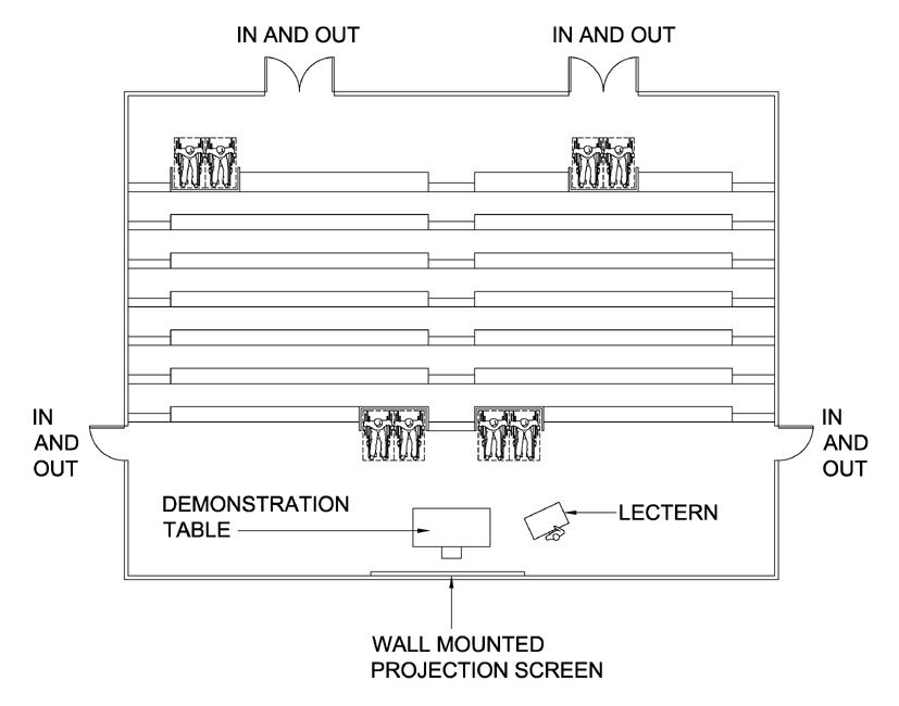
A minimum of four wheelchair spaces shall be provided at spectator level in the auditorium with not more than 800 fixed seats. For auditorium with more than 800 fixed seats at spectator level, two wheelchair spaces shall be provided for every 400 fixed seats and any part thereof. (For example, at least six wheelchair spaces shall be provided if there are 900 fixed seats.) The spaces shall be grouped in pairs (not less than two) and also not separated from the seats for other audiences. Each wheelchair space shall have unobstructed line of vision to the stage areas at which the relevant activity takes place, and be of minimum size of 800 mm x 1300 mm, with the side of 800 mm facing towards the stage podium or screen. The minimum width of the passage leading to a wheelchair space from an accessible entrance of the auditorium shall not be less than 1500 mm. (see Figure 1A)
Division 1 --- AUDITORIUM AND RELATED FACILITIES
MANDATORY SECTION Performance Objectives
3. In this Division, “relevant activity” means the activity for the purpose of which the audience in the premises attend the premises.
Figure Wheelchair Space in an Auditorium
1A –

*ALL DIMENSIONS ARE IN mm
12
TOP VIEW
SIDE VIEWSIDE VIEW
(b) The wheelchair spaces should be so located that the wheelchair user may have the choice of sitting with another wheelchair user or conventionally seated companion.
Obligatory Design Requirements (Cont’d)
BEST PRACTICE SECTION
Braille and Tactile Fire Exit Maps and Tactile Warning Strips
(2) Tactile warning strips complying with paragraph 26 shall be provided at both the top and bottom ends of the staircases leading to the stage.
(e) Safety barrier should be provided to wheelchair spaces located at high level to minimise the risk of the wheelchair falling over the edge.
(1) Braille and tactile fire exit maps as shown in Figure 32 shall be provided at all entrances to the auditorium.
5.
A. Design Considerations
13
The auditorium, the stage, backstage facilities, changing rooms, rehearsal rooms, dressing rooms, rest rooms, toilets and shower rooms shall be accessible to wheelchair users. If there is an access connecting two or more of them, an equivalent accessible route shall be provided for wheelchair users, e.g. by a ramp in compliance with Division 5, an accessible lift in compliance with Division 19.
(a) Seating allocation for persons with a disability should be accessible by provision of a direct, easily identifiable route free from obstructions, and preferably adjacent to the means of egress and accessible toilets.
(d) It is a good practice to provide wheelchair spaces at different levels of the seating area in order to have a variety of viewing locations. An example of wheelchair space arrangement is shown in Figure 1B.
6.
Access for Wheelchair Users
(c) The lines of sight provided by the wheelchair spaces should be comparable to those of other normal viewing positions.
(e) Where conventional seat numbers are provided, Braille and tactile seat number should be provided at the top of each seat rest. The specification of Braille cells is provided in Figure 31.
(a) A conventional companion seat may be provided next to each wheelchair seating location.
Figure 1B – Example of Wheelchair Spaces in a Lecture Hall
(c) Access should be provided to the low and high levels of the auditorium.
(f) Sound enhancement system may be provided at the designated areas for persons with hearing impairment.
14
(d) Two to three rows of removable seats should be provided in the auditorium for the use by large group of wheelchair users for special function / occasions.
(b) Removable seats may be provided in wheelchair seating locations for spare use by persons other than wheelchair users.
B. Recommended Design Requirements
The bathroom and shower facilities serving an accessible guest room shall comply with Division 12.
A. Design Considerations
Performance Objectives
(b) In addition, it is important to ensure that the built-in wardrobes and shelving in all guest rooms are accessible and convenient to use.
15
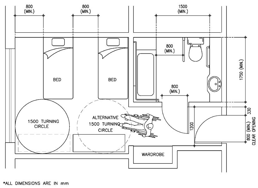
7. Guest Rooms
A typical guest room layout is shown in Figure 2 and typical bathroom and shower compartment are shown in Figure 27.
MANDATORY SECTION
(a) Within an accessible guest room, wheelchair user should be able to manoeuvre around and use the facilities in the room, and operate switches and controls. The internal layout should be large enough to enable a wheelchair user to transfer to one side of a bed, with or without assistance.
BEST PRACTICE SECTION
B. Recommended Design Requirements
(2) A minimum of two accessible guest rooms with full facilities for persons with a disability shall be provided in a hotel, hostel and guesthouse. Two such accessible rooms shall be provided for every 100 guest rooms and any part thereof. (For example, a total of four such accessible rooms shall be provided if there are 150 guest rooms.)
Division 2 --- HOTELS, HOSTELS AND GUESTHOUSES
(1) The accessible guest rooms provided in a hotel, hostel or guesthouse shall be accessible by persons with a disability not only to the rooms but also to all sleeping, bathing and sanitary facilities in the rooms.
This Division is applicable to guest rooms designated for the use of persons with a disability in hotels, hostels and guesthouses.
Obligatory Design Requirements
Minimum Provision
CLEAR MANOEUVRING SPACE SHALL NOT BE LESS THAN 1500x1500 MEASURED AT 350 ABOVE FINISHED FLOOR LEVEL
Figure 2 – Typical Guest Room Layout

16
*ALL DIMENSIONS ARE IN mm
10. Marking Requirements for Accessible Parking Spaces
8. Ratio of Accessible Parking Spaces
9. Requirements for Accessible Parking Spaces
(1) The parking spaces reserved for persons with a disability shall be located in proximity and with an accessible route to the lobby with an accessible lift or entrance.
(1) Adequate numbers of accessible car parking spaces shall be provided with proper access, proper designation and directional signage in the carparks.
Performance Objectives
MANDATORY SECTION
Obligatory Design Requirements
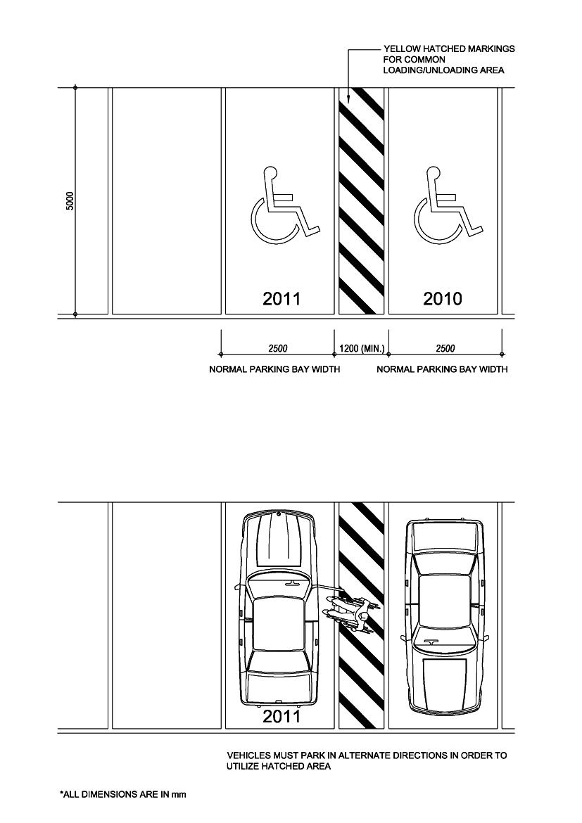
(4) The common loading/unloading area shall be of at least 1200 mm wide and be marked with yellow hatched markings as shown in Figure 4.
(2) Total No. of Car Parking Space in Lot Required No. of Accessible Car Parking Spaces 1-50 1 51-150 2 151-250 3 251-350 4 351-450 5 Above 450 6
This Division aims to provide standards for accessible car parking spaces designated for the use of persons with a disability.
Division 3 --- CARPARKS
The parking space shall be clearly marked with the international symbol of accessibility and the parking space number on the floor as shown in Figure 3.
17
(3) Where a common loading/unloading area is provided between two parking spaces for persons with a disability, such parking spaces shall be not less than 2500 mm in width.
(2) The minimum width for a parking space for persons with a disability shall be 3500 mm.
18 Figure 3 – Dimension and Identification of Car Parking Space for Persons with a Disability *ALL DIMENSIONS ARE IN mm 1500 1500 3500 (MIN.) 2500 3500 (MIN.) 2500

19 Figure 4 – Side by Side Parking Spaces for Persons with a Disability *ALL DIMENSIONS ARE IN mm 1500 1500 2500 25001200 (MIN.)
(b) The parking bay surface should allow the safe transfer of a passenger or driver to a wheelchair and transfer from the parking bay to the access route to the building without undue effort, barriers to wheelchairs or hazards from tripping.
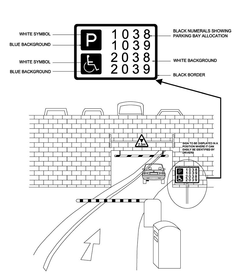
(a) At the entrance of public parking facilities, signage should be displayed in prominent positions to indicate the designated numbers of the parking spaces reserved for persons with a disability (see Figure 5).
BEST PRACTICE SECTION
A. Design Considerations
(b) Indication / directional signage along driveway showing the way leading to the parking spaces reserved for persons with a disability should be provided.
20
B. Recommended Design Requirements
(a) Persons with ambulant impairment who arrive as passengers should be able to alight conveniently from a vehicle close to the principal entrance, or alternative accessible entrance, of the building.
(c) Where a ticket dispensing machine is installed, it should be located properly to allow wheelchair users, or persons of short stature, to approach conveniently to the machine and perform the payment and ticket dispensing functions.
21
5
Figure – Parking Space Indication Signage
11. Provision of Access Route
This Division aims to ensure proper access for all people, with or without disabilities to approach, enter or leave a building independently to reach and use its facilities, such as foyers, lifts, toilets, shops, restaurants, cinemas, etc. without undue difficulty.
13. Tactile Guide Path
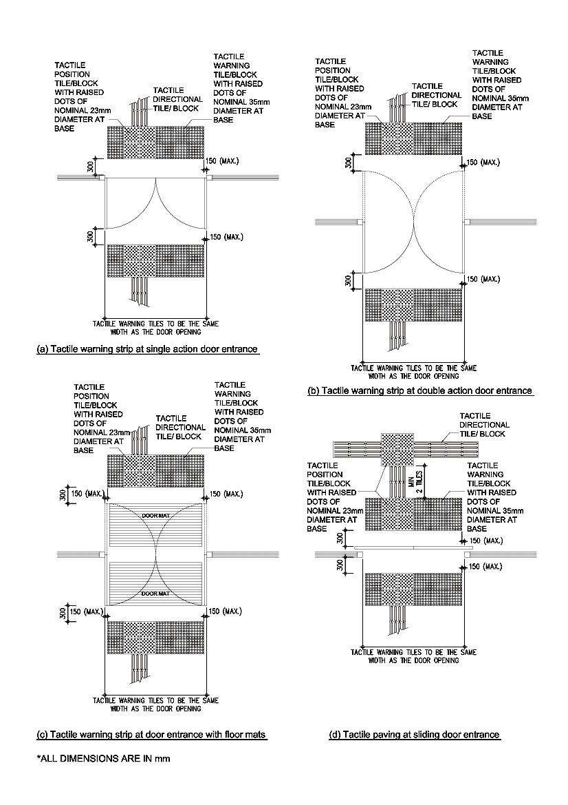
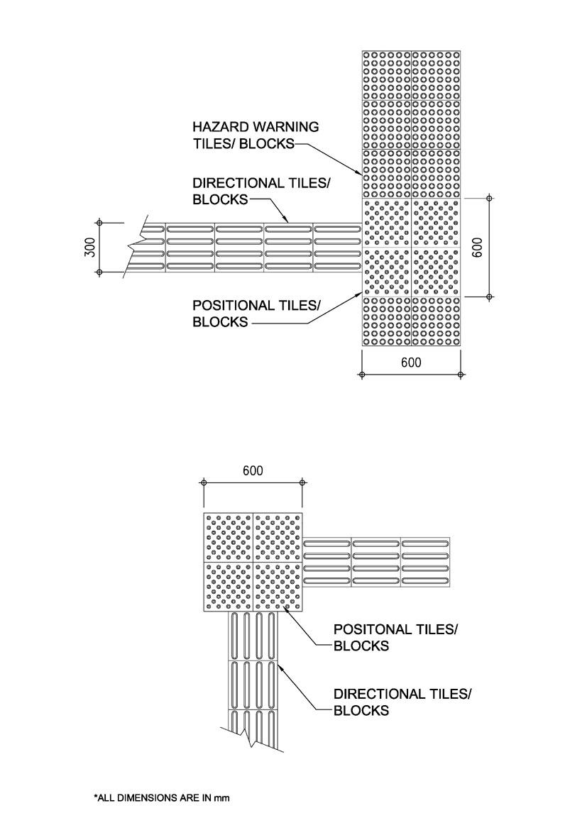
For categories of buildings as required in Table 2, such access shall be provided with a tactile guide path as illustrated in Figures 6A and 6B. Examples of specification of tactile tile/block are shown in Figure 6C.
Division 4 --- ACCESS ROUTE
(3) The surface of an access route shall be firm.
Width
(2) Such access shall be free from protrusion hazards, steps, kerbs other than dropped kerbs, steep ramps, doors or doorways which will impede the passage of a wheelchair, or other form of barrier which will prevent access by persons with a disability.
Obligatory Design Requirements
An easily identifiable continuous and relatively level path free from obstruction or any kind of hazards shall be provided for persons with a disability to enter, move within and leave a building to reach the accessible facilities.
MANDATORY SECTION Performance Objectives
In case where the main entrance is not an accessible entrance or it is impractical to provide a commonly used entrance at prominent point on the lot boundary due to difficult terrain or unusual characteristics of the site (e.g. in the case of a sloping site or presence of steep access road/driveway), this would be acceptable provided that persons with a disability could reach the building by means of vehicle and adequate directional signs shall be posted at conspicuous location of the main entrance to show clearly the location of and the route to an accessible entrance.
12. Requirements for Access Route
Access shall be provided from a prominent point or points on the lot boundary, which is accessible to a public street or pedestrian way, directly to at least one entrance which is commonly used by the public or to a point directly adjacent to one entrance which is commonly used by the public and to an accessible lift, unless it is impractical to do so because of difficult terrain or unusual characteristics of the site.
(1) The clear width of an access route shall be not less than 1050 mm.
Free from Barriers
Surface
22
*ALL DIMENSIONS ARE IN mm
23
Figure 6A – Tactile Guide Paths at Building Entrances Linking up with Initial Access on the Lot Boundary and Interior Facilities
24
Figure

POSITIONAL TILES/ BLOCKSDIRECTIONAL TILES/ BLOCKS

6B – Typical Tactile Guide Path Junction *ALL DIMENSIONS ARE IN mm
*ALL DIMENSIONS ARE IN mm
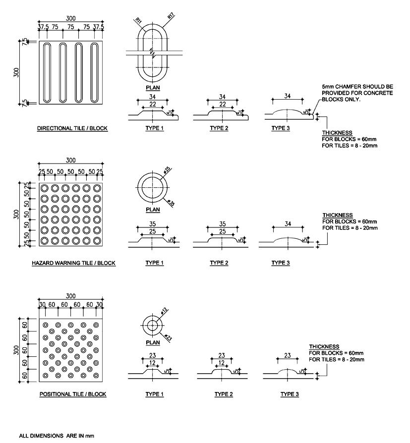
This has raised big dots (35mm in diameter) arranged in square grid parallel to the sides of the slab for indication of potential hazards ahead. This type of tile/block could be used alone to form tactile warning strips at the top and bottom ends of staircase or ramps, and at dropped kerb.
/
25
This has raised small dots (23mm in diameter) placed in staggered positions for indication of possible change in walking directions. – Examples of Details of Tactile Warning Tiles Blocks
ii) Hazard Warning Tile/Block
i) Directional Tile/Block
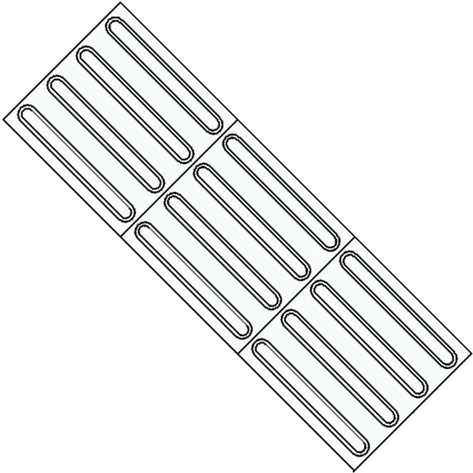
This has parallel raised bars for guiding the users along an intended safe path.
iii) Positional Tile/Block
Figure 6C
Three kinds of tactile tiles/blocks as shown in Figure 6C are commonly used in constructing a tactile guide path:
Floor Space
(d) Indication signage for accessible entrances should be provided where more than one entrance exist in a complex building.
Surface
(c) The surface of the access should be firm and slip-resistant with a “static coefficient of friction” of “Good” grading (see Appendix C).
(a) The clear width of the access route should not be less than 1500 mm.
(b) In large floor space of more than 200m2 where the cues of physical edges such as walls and handrails are not present, tactile guide paths should be used to facilitate orientation of persons with visual impairment.
(c) Easily identifiable access route e.g. tactile guide path for persons with visual impairment should be provided from the lot boundary to the entrance of a building.
(b) Access routes from the lot boundary to the entrance of a building should be wide enough to allow wheelchair users and other users to pass simultaneously.
Width
B. Recommended Design Requirements
A. Design Considerations
BEST PRACTICE SECTION
26
(a) In designing an access to the building, it should be recognised that changes in level are difficult for many people to negotiate, including wheelchair users, people who use walking aids and persons with visual impairment.
15. Width
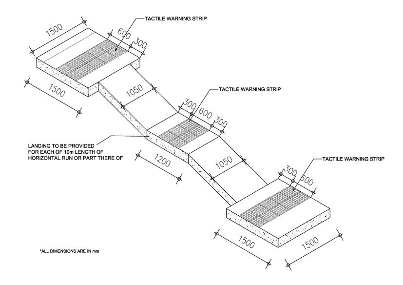
(a) a landing of not less than 1200 mm long for each 10 m length of horizontal run or part thereof; (see Figure 7)
(c) tactile warning strips at the head, foot and landings (see Figure 7).
A ramp shall not be less than 1050 mm in width.
16. Landing
27
17. Running Slope and Length
(2) The above items shall not apply to ramp access to lift or ramp with a length less than 300 mm.
(1) If the gradient of a ramp is 1 in 20 or steeper, the ramp shall be provided with :-
14. Ramps of an appropriate design shall be provided at all changes in level other than those served by an accessible lift or accessible lifting mechanism accommodating the specific requirements of persons with a disability.
Maximum slope Maximum length Maximum rise 1:10 i.e., 10% 1500mm 150mm 1:8 i.e., 12.5% 600mm 75mm
18. Requirements for Ramps
Combination of ramps of minor rise as stated in paragraph 17 shall not be permitted.
19. Protection and Surface
MANDATORY SECTION Performance Objectives
(b) handrails complying with Division 8 on both sides; and
A ramp is a sloping walkway leading from one level to another.
A clear space of not less than 1500 mm x 1500 mm shall be provided at the head and foot of every ramp, i.e. door swing and alike shall not be allowed to swing onto the landing.
No ramp shall be steeper than 1 in 12 gradient except in the following situations of minor rise : -
Obligatory Design Requirements
(1) Any ramp with a rise greater than 200 mm, leading down towards an area where there may be vehicular traffic, shall have a railing or barrier across the full width of its lower end, and be not less than 1500 mm from the foot of the ramp.
Division 5 --- RAMPS
28
(2) Raised traction strip shall be avoided.
(4)&(5) No appliances, fixtures and fittings shall project beyond 90 mm from the surface of any wall below a level of 2000 mm above the ramp level unless they are unavoidable, in which case they shall also be extended downwards to the ramp level or be guided by tactile flooring materials.
(6) The floor and wall along ramps shall be in contrasting colours.
Obligatory Design Requirements (Cont’d)
(3) A kerb of at least 100 mm high, or a rail 200 mm above ramp level shall be provided on both sides to prevent wheelchair from slipping over the edge.
Figure 7 - Tactile Warning Strips and Landings for Ramps *ALL DIMENSIONS ARE IN mm LANDING TO BE PROVIDED FOR EACH OF 10m LENGTH OF HORIZONTAL RUN OR PART THEREOF
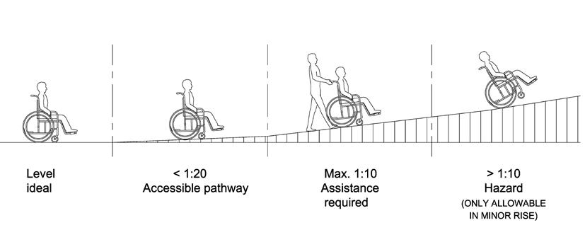
(b) The more gradual the slope of the ramp (i.e. the less steep it is) the more easily persons can use it without assistance. Therefore, slope with the ratio of 1:20 (5%) to 1:15 (6.7%) is preferred. It can take much energy to get up ramp with steep gradient, which also makes speed control difficult when going down. Steep inclines can put a wheelchair in danger of tipping backwards or forwards as many users cannot lean or adjust their balance to accommodate gradient (see Figure 8).
Figure 8 - Running Slope and Length
BEST PRACTICE SECTION
(e) A ramp that surmounts a major change in level has to be very long, and requires multiple ramp and landing combinations. In such circumstances, other design solutions should be considered.
A. Design Considerations
(d) A ramp should have handrails on both sides so that it can be used in both directions by people with a mobility problem on one side such as may be the case for stroke sufferers.
(a) Where there is a change in level, the provision of a ramp is an effective method to ensure largely independent accessibility for persons with a disability and the elderly. Interior ramp is preferred as a means of egress to stair as it accommodates a wider range of building user, including wheelchair user.
29
(c) A level resting space outside the swing of any door at the top of a ramp should be provided to avoid the possibility of ‘roll-back’ for wheelchair user when trying to open the door.
(f) A curved ramp is not a preferred design solution. Similarly a cross fall can put a wheelchair user at risk and may adversely affect steering, particularly on manually propelled chair.
(d) Tactile warning strips at the head, foot and landing should have a minimum luminous contrast of 70% with the adjoining surfaces.
1:20 i.e., 5.00% 10000 mm 500 mm
1:14 i.e., 7.14% 4200 mm 300 mm
(c) A ramp should have slip-resistant surface with a minimum “static coefficient of friction” of “Very Good” grading (see Appendix C).
Maximum slope Maximum length Maximum rise
1:12 i.e., 8.33% 1800 mm 150 mm
B. Recommended Design Requirements
30
(a) A ramp should have a running slope 1:12 (8.33%) to 1:20 (5%).
(e) The floor and wall along a ramp should have a minimum luminous contrast of 30%.
(b) Width should be at least 1200 mm to enable a wheelchair to turn or preferably at least 1500 mm to allow 2 wheelchairs to pass.
1:16 i.e., 6.25% 6400 mm 400 mm
21. Requirements
Performance Objectives
Division 6 --- DROPPED KERBS
MANDATORY SECTION
Dropped kerbs shall be of appropriate design and provided with adequate visual and tactile warning.
Obligatory Design Requirements
Dropped kerb shall be constructed as follows: -
A dropped kerb is a ramp built on a footpath or pavement to accommodate the change in level towards vehicular areas.
(f) provided with a tactile warning strip of the nominal width of 600 mm at the ramp.
20. General Provision
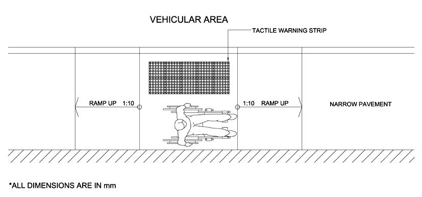
Changes in level at kerbs shall be by a dropped kerb as illustrated in Figure 9. Dropped kerb shall be provided at pedestrian crossing and at each end of the footpath of a private street or access road. Kerb separating footpath or ramp from vehicular area shall also be a dropped kerb.
(a) not less than 1200 mm in length and 1200 mm in width; (b) with a clearance of at least 800 mm long at the back of the footway; (c) ramped at a gradient not steeper than 1:10;
31
(d) with a level difference of not more than 15 mm with the vehicular areas; (e) provided with a tactile warning strip at 300 mm from the vehicular areas; and
Raised traction strips shall be avoided.
32
23. Surface
1200 (MIN.)
Obligatory Design Requirements (Cont’d)
Dropped kerb shall be so located to enable users to have an unobstructed view of traffic approaching from any direction.

22. Location
Figure 9 – Dropped Kerb
Luminous Contrast
(c) Dropped kerb should be provided where necessary and in conjunction with pedestrian crossings, which should include visible, audible and tactile crossing devices with traffic lights.
(b) The tactile warning strip should be provided in order to notify the presence of traffic.
(c) The tactile warning strip should have luminous contrast for the elderly and persons with visual impairment.
Slip Resistance
Conjunction with Pedestrian Crossings
(e) Examples of dropped kerb are shown in Figures 10, 11 and 12.
B. Recommended Design Requirements
(b) Tactile warning strip should have a minimum luminous contrast of 70% with the adjoining surfaces.
(d) Dropped kerb should have slip-resistant surface. Raised traction strips should be avoided in order to reduce the hazard to everyone.
A. Design Considerations
(a) Dropped kerb should have slip-resistant surface with a minimum “static coefficient of friction” of “Very Good” grading (see Appendix C).
(a) The provision of a dropped kerb is to overcome potential hazard arising from change in level for persons with or without a disability.
BEST PRACTICE SECTION
33
34 Figure 10 - Examples of Design of Dropped Kerb *ALL DIMENSIONS ARE IN mm 15 15mm

35 Figure 11 – Dropped Kerb at Street Corner Figure 12 – Dropped Kerb for Access Road and Narrow Pavement *ALL DIMENSIONS ARE IN mm *ALL DIMENSIONS ARE IN mm (Pavement less than 2000 mm wide)

Steps and staircases shall be intended as an alternative to lift access in buildings and shall be of adequate design to allow all persons, with or without a disability, to travel safely and independently.
36
(i) be constructed with treads not less than 225 mm in width (measured at the centre of the flight) from the face of one riser to the face of the next riser and with risers not more than 175 mm in height;
MANDATORY SECTION Performance Objectives
(iii) have not more than 16 steps in any flight without the introduction of a landing;
The required staircases and the main circulation staircase in common areas of a building shall:
(vi) have risers reduced to not more than 160 mm high and treads increased to not less than 280 mm wide for greater ease of use for external steps and stairs.
(v) be provided with non-slip nosing in contrasting colour; and
Colour Contrast
(vii) Treads and walls of a staircase shall be in contrasting colours.
(ii) have risers built with vertical or receding face not more than 15 mm from the vertical, without a projecting nosing;
(iv) be provided on both sides with properly fitted handrails (see paragraph 28(2));
24. This Division applies only to the required staircase and the main circulation staircase in the common areas of a building, and sets out requirements to help people including persons with ambulant disabilities and persons with visual impairment to negotiate steps and staircases.
Obligatory Design Requirements
Division 7 --- STEPS AND STAIRCASES
25. Dimension and Orientation
27. Avoidance of Projection
No appliances, fixtures or fittings shall project beyond 90 mm from the surface of any wall in a staircase below a level of 2000 mm above the treads of the staircase unless they are unavoidable, in which case they shall also be extended downwards to the level of the treads.
Tactile Warning Strip
Obligatory Design Requirements (Cont’d)
37
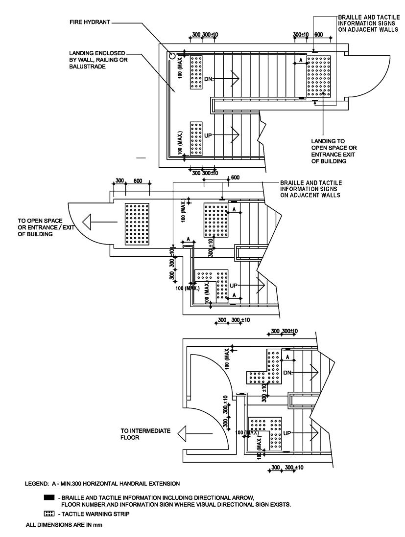
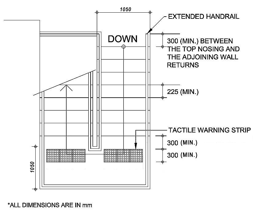
Tactile warning strips shall be provided at landings and at both the bottom and top ends of a staircase, regardless of the number of steps it comprises. For landings leading to a floor or those enclosed by wall, railing or balustrade, tactile warning strips of 300 mm in width shall be provided; for those leading to an open space or the entrance / exit of a building, the tactile warning strips shall be 600 mm in width (see Figure 13). In this case, Braille and tactile information signs shall be provided on the adjacent wall to indicate the presence of an opening. For a staircase with intermediate steps between two flights, the provision of tactile warning strips shall follow the arrangement in Figure 13.
26.
38 Figure 13 – Arrangement of Tactile Warning Strips and Handrails at Staircases *ALL DIMENSIONS ARE IN mm EXIT 岀口 Braille and tactile information LEGEND: A - MIN. 300 HORIZONTAL HANDRAIL EXTENSION - BRAILLE AND TACTILE INFORMATION INCLUDING DIRECTIONAL ARROW, FLOOR NUMBER AND INFORMATION SIGN - TACTILE WARNING STRIP


(e) When ascending a stair, people who wear calipers or who have stiffness in hip or knee joints are particularly at risk of trapping the toes of their shoes beneath projecting nosings.
39
(h) The provision of Braille and high luminous contrast signs is recommended. For persons with visual impairment, high luminous contrast, larger font, more prominent and well-defined shape of sign/signage is recommended.
A. Design Considerations
(a) Where steps or stairs are in an accessible route, complementary ramps, lifts or escalators should be provided.
(b) All steps should be uniform.
(c) Circular stair and sloped landing should be avoided.
BEST PRACTICE SECTION
(g) Unawareness of steps is dangerous to persons with visual impairment. Timely tactile or audible warning of change in level is therefore essential. Warning should be placed sufficiently in advance of any potential dangers.
(i) Despite the design requirements of tactile guide paths and tactile warning strips would help orientation for persons with visual impairment, they sometimes impose hazards to people with limited mobility, children and the elderly.
(d) It is necessary to provide safe and well-dimensioned staircase for the comfort of all people, especially those with mobility problems.
(f) Stair should be designed with more generous dimensions, e.g. wider tread, and shorter travel distance is recommended. Open risers should be avoided.
Dimension and Orientation
(d) Winder, spiral staircase and splayed step should be avoided.
*ALL DIMENSIONS ARE IN mm
(b) Individual flight should not exceed 1800 mm in height nor a total of 12 risers.
B.
40
Recommended Design Requirements
(e) Non-slip nosing should have a minimum luminous contrast of 30% with the adjoining surfaces.
(f) Treads of staircase should have a minimum luminous contrast of 30% with the walls.
Figure 14 – Example of Staircase Plan for Persons with a Disability

Luminous Contrast
(a) For any internal stair with heavy circulation, riser should be reduced to 150 mm high and tread be increased to 300 mm wide for greater ease of use.
(c) The top nosing of any flight should be built not less than 300 mm from the point at which the adjoining wall returns (see Figure 14).
41 Division 8 --- HANDRAILS
(3)&(4) Handrail shall be:
29. Loading
(1) Handrail shall be installed to resist a load of not less than 1.3 kN applied vertically or horizontally.
(1) Handrail to ramp and step shall be fixed not less than 30 mm and not more than 50 mm clear of wall and with a clear height of 70 mm from the top of the bracket to the top of the handrail.
Obligatory Design Requirements
(i) tubular, not less than 32 mm and not greater than 50 mm in external diameter; or (ii) in other shapes that can provide the user a grip similar to that specified in the case of tubular handrails.
Typical handrail sections are shown in Figure 15.
28. Dimension and Shape of Handrail
MANDATORY SECTION Performance Objectives
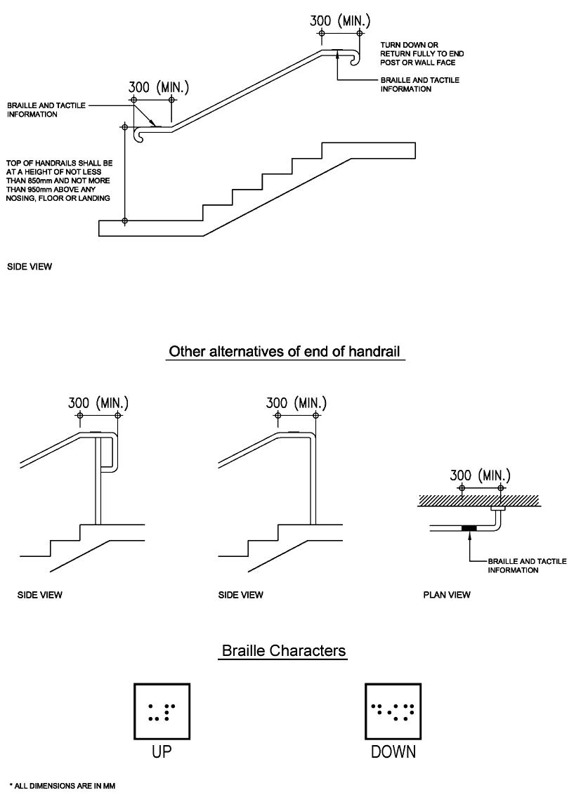
(5)&(6) Handrail shall extend horizontally not less than 300 mm beyond the first and last nosing of every flight of steps or beyond the ends of a ramp and terminate into a closed end which shall turn down or return fully to end post or wall face and which shall not project into a route of travel. Where a door opening is in place, a shortened extension of not less than 100 mm shall be permitted.
Handrails provide support for everyone and are especially helpful for persons with a disability and the elderly to use staircases, to pull themselves up inclines, check themselves on declines and to assist them in moving within the building.
(2) The top of handrail shall be at a height of not less than 850 mm and not more than 950 mm above any nosing, floor or landing.
(2) Handrail shall not rotate within its fixing fittings.
Handrails shall be of the correct sizes, strengths and shapes and be conveniently located to provide secure hand-grips, and be capable of taking the entire weight of the persons using them.
42 Figure 15 - Handrails *ALL DIMENSIONS ARE IN mm

Braille and tactile information on directional arrow and floor number shall be provided on handrail on every floor at a designated location as illustrated in Figures 16A to facilitate persons with visual impairment. Where a directional sign exists on handrails, Braille and tactile information shall also be provided as illustrated in Figure 13.
Obligatory Design Requirements (Cont’d)
43
30. Braille and Tactile Information
44 Figure 16A – Handrails of Staircase *ALL DIMENSIONS ARE IN mm

BEST PRACTICE SECTION
A. Design Considerations
(a) Handrail should be designed to provide easy, firm and comfortable grip to all users and should have no obstruction when people slide their hands along the handrail.
(b) The installation level of the handrail and clearance dimensions should facilitate a safer grip and prevent hand injuries especially for the elderly and persons with visual impairment.
B. Recommended Design Requirements
(b) A recess containing a handrail should extend not less than 450 mm above the top of the handrail as illustrated in Figure 16B.
Clear Space
45
(e) Handrail should be set at a height that is convenient for all users of the building and should extend safely beyond the top and bottom of a flight of steps, or a ramp, to give both stability and warning of the presence of a change in level.
(c) Handrail finished in more noticeable colours with Braille and tactile information should facilitate self-help circulation of persons with visual impairment.
(d) The materials and shapes of handrail should be carefully designed to suit the elderly. In addition, handrail designed with different levels of grab bars should be recommended for different users’ purposes.
(a) Where the wall has a rough surface, the clear space should be not less than 45 mm between the handrail and the wall.
(c) One more handrail should be provided at a height of not less than 700 mm and not more than 800 mm above any nosing, floor or landing for schools and places of public entertainment.
Double Handrail
Luminous Contrast
46
Figure 16B – Handrail in Recess
(d) Handrail should have a minimum luminous contrast of 30% with the surrounding wall surfaces. DIMENSIONS ARE IN mm
*ALL

Division 9 --- CORRIDORS, LOBBIES AND PATHS
Corridors are passages providing for internal circulation within a building. Lobbies provide interceptions at entries to staircases or lifts and connections to corridors where appropriate.
MANDATORY SECTION
31. Manoeuvring Space
32. Channel Covers
(3) any lobby in a corridor shall have a length of not less than 1200 mm, excluding space for door swings;
(5) this paragraph shall not apply to lobby which lead to staircase only.
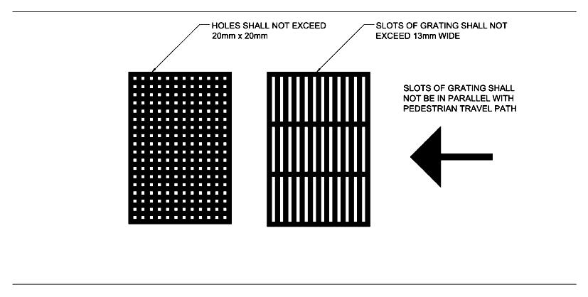
Slot of gratings shall have a width of not more than 13 mm and shall not be parallel with pedestrian travel path (see Figure 17).
33. Gratings
(1) area shall have a clear width of not less than 1050 mm;
Obligatory Design Requirements
47
Space shall be allowed for manoeuvring wheelchairs in corridor, lobby, path and similar areas as follows:
(2) a space not less than 1500 mm x 1500 mm shall be provided within 3500 mm of every dead end;
Corridors, lobbies and paths shall be designed to an appropriate standard to allow all people to travel within a building safely and independently.
(4) a level area, extending not less than 1200 mm beyond the swings of the doors and not less than 1500 mm in width shall be provided on both sides of every entrance of a building; and
On footpath, cover to a channel shall be flush with the surface of the footpath. Any hole in such cover or between such covers shall have a dimension of not more than 20 mm.
Performance Objectives
For the purpose of this paragraph, “dead end” is a corridor, lobby or path where the means of exit for persons with a disability is in one direction only.
35. Controlled Passage
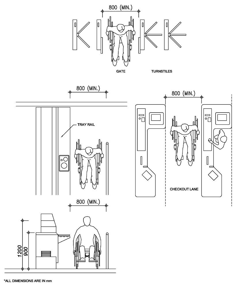
For cashier counter, security device installed at shop entrance or turnstile controlled passage accessible to the public, each shall have at least one path of minimum 800 mm in width for the use by wheelchair users and clearly marked with international symbol of accessibility, unless an alternative passage adjacent to the controlled passage is provided. (see Figure 18)
SLOTS OF GRATING SHALL NOT BE PARALLEL WITH PEDESTRIAN TRAVEL PATH
48
Figure 17 – Grating Size and Orientation
34. Protrusion
No appliances, fixtures and fittings shall project beyond 90 mm from the surface of any wall in corridors, paths and lobbies below a level of 2000 mm above the finished floor level unless they are unavoidable, in which case they shall also be extended downwards to the finished floor level or guided by tactile flooring materials.
49 Figure 18 – Width of Controlled Passages *ALL DIMENSIONS ARE IN mm
Obligatory Design Requirements (Cont’d)
Where the headroom is 2000 mm or less from the finished floor level, a warning guardrail or other barrier shall be provided for detection, having its leading edge at or below 680 mm above the finished floor level (see Figure 19).
36. Headroom
* DIMENSIONS ARE IN mm
ALL
50
Figure 19 – Overhead Hazard

(a) Corridors, lobbies and paths should be designed to have appropriate dimensions to allow people using wheelchair or other forms of mobility aids to pass others on the access route.
BEST PRACTICE SECTION
(a) Path width should be more than 1200 mm to enable a wheelchair user to pass anyone who is on the same path or preferably at least 1500 mm to allow two wheelchairs to pass. At right angle turns, inside corner should be splayed or rounded to at least 300 mm radius. (see Figure 20)
B. Recommended Design Requirements
51
A. Design Considerations
Width
(d) Protruding object can be extremely hazardous to the persons with visual impairment as well as the general public. Examples of protruding obstruction are sign, drinking fountain, fire extinguisher, telephone enclosure, and underside of stairway or escalator, etc. Protruding object should be recessed into the wall as far as possible.
(b) To facilitate the way finding for persons with visual impairment, surfaces and finishes with luminous contrast between the wall and the ceiling, and between the wall and the floor should be adopted. Appropriate lighting design with adequate illumination should also be considered.
(c) Adequate manoeuvring space for wheelchair particularly in lobby and corridor of domestic building should be provided in order to facilitate the wheelchair users in passing through corridor especially when turning through 180° is required.
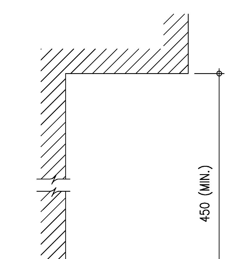
52 Figure 20 – Dimension and Space Allowance for Corridor in Building *ALL DIMENSIONS ARE IN mm D
D. A CLEAR WIDTH OF CORRIDOR SHOULD NOT BE LESS THAN 1200mm
B. DEPTH OF RECESS SHOULD NOT BE LESS THAN THE WIDTH OF THE DOOR LEAF.

A A CLEAR WIDTH OF 1500mm WILL ALLOW TWO WHEELCHAIR USERS TO PASS EACH OTHER.
C. 900mm CLEAR SPACE WHERE DOORS OPEN INTO A CORRIDOR.
53
(g) Protruding object should include but not limited to sign, telephone enclosure, drinking fountain, fire extinguisher, underside of stairway or escalator.
(f) The protruding object should not reduce the statutory required clear width and height of access and manoeuvering space. (see Figure 21)
(d) Hazards on floor, caused by unnecessary projection or by unexpected change in level should be avoided.
(h) Where it is reasonable to anticipate visit of persons with visual impairment, protruding object should be avoided at pedestrian areas include walkway, hall, corridor, aisle, lobby, mall and all areas open to the public.
Protruding Objects
Luminous Contrast
(b) All corridors should have slip-resistant surfaces with a “static coefficient of friction” of “Good” grading (see Appendix C).
B. Recommended Design Requirements (Cont’d)
Surface
(e) A minimum luminous contrast of 30% should clearly define between wall, floor and door surfaces.
(c) Surface paved with loose gravel or stone is hazardous and should be avoided.
54 Figure 21 – Examples of Design to Cater for Protrusion Hazards *ALL DIMENSIONS ARE IN mm

MANDATORY SECTION
Obligatory Design Requirements
39. Unobstructed Area
(1) The unobstructed area adjacent to the door handle on the leading face of a single door shall not be less than 330 mm in width. (see Figure 22)
55 Division 10 --- DOORS
37. The requirements of this Division apply to doors on accessible routes.
38. Width of Doors
Door, including one leaf of a pair of double doors, shall have a clear width of not less than 800 mm between the open door and opposite jamb or the other leaf. (see Figure 22)
Doors and doorways shall be designed to enable all people especially wheelchair user to enter and leave any room unaided or without undue difficulties.
(2) Door, if less than 330 mm from the corner of a room, shall swing from the side nearer to that corner.
Performance Objectives
56
Double-action self-closing door shall have a check mechanism to prevent the door swinging beyond the closed position and a transparent vision-panel with a bottom edge not more than 1000 mm above the floor and the top edge not less than 1500 mm above the finished floor level.
*ALL DIMENSIONS ARE IN mm
Figure 22 – Plan of Door Suitable for Wheelchair
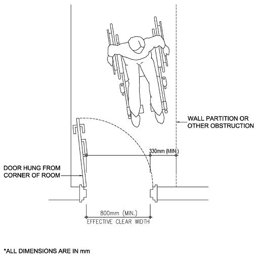
Door handle shall not be less than 950 mm and not more than 1050 mm above the finished floor level, measured from the top surface of the grip.
Double-action Self-closing Doors
40.
41. Handles
(c) All doors should be wide enough to allow unrestricted passage for different users, including wheelchair users, people carrying luggage and parents with baby carriages and small children.
Door threshold shall not exceed 20 mm in height and shall be bevelled to facilitate passage of wheelchairs.
Obligatory Design Requirements (Cont’d)
57
45.
BEST PRACTICE SECTION
Door closing devices shall be designed to allow exterior and interior doors to be opened with horizontal force of not more than 30 N and 22 N respectively. Door required to have fire resistance period installed along accessible routes shall be opened with horizontal force of not more than 30 N. Closer for interior door shall have a closing period of at least 3 seconds measured from an open position of 70° to a point 75 mm from the closed position measured from the leading edge of the door. Door closing devices include door closer, spring hinge and floor hinge.
A. Design Considerations
42.
44.
43. Door Closing Devices
Door Thresholds
If frameless glass door is used, it shall be prominently marked so as to make it visible. The marking shall be placed across on the glass door such that at least a portion of the marking is placed between 900 mm and 1500 mm above the finished floor. The colour marking shall also be provided to glass panel adjacent to the glass door.
Automatic Main Entrance Doors
Automatic door shall be provided to one of the main entrances, which is commonly used by the public, of sports stadium, town hall, civic centre, theatre, museum, public library, shopping complex, sports complex, public swimming pool complex, office building, hotel and hospital.
(a) Door may be manually operated without powered assistance, or power operated under manual or automatic control. An automatically operated sliding door is a preferred solution for most people as it avoids the risks associated with automatic swing door and its use can make it possible to reduce the length of entrance lobbies.
(b) A door fitted with a self-closing device to stand against wind force is difficult to be openable by many people, particularly those who are wheelchair users or who have limited strength. Where closing devices are needed for fire control, the use of electrically powered hold open devices or swing-free closing devices is appropriate.
Frameless Glass Doors
58
(d) Sufficient space alongside the leading edge of a door should be provided to enable a wheelchair user to reach and grip the door handle, then open the door without releasing hold on the handle and without the wheelchair footrest colliding with the return wall.
Automatic Door Openers
(i) remain open for a minimum of 5 seconds; (ii) have a guardrail where it opens into a route of travel (see Figure 23); (iii) have a sign showing automatic door; and (iv) be located outside of the door swing.
External Doors
(d) Automatic door opener should be provided on the main entrance door of buildings not included in paragraph 45 and should:-
(a) External door should be single-action and open outwards to obviate high tension in spring closers in sustaining wind pressure.
(b) Where door is latched, lever-type handle should be used.
(e) The presence of door, whether opened or closed, should be apparent to persons with visual impairment through the careful choice of colour and materials for the door and its surroundings. Provision of marking on glass doors would help persons with visual impairment to distinguish obstacles and passage as well as for public to avoid collision.
Kick-plates
(c) All doors which allow the passage of wheelchairs should have kick-plates of not less than 200 mm high fitted on the face which swings away.
A. Design Considerations (Cont’d)
B. Recommended Design Requirements
Sliding automatic door with overhead sensor operating device or manual large button control should be provided.
Latched Doors
(f) The leading edge of glass door should be marked to indicate glass.
Luminous Contrast
mm
(e) Transparent vision-panel should be provided to door in between accessible path. The vision-panel should be installed with bottom edge not more than 1000 mm and top edge not less than 1500 mm above the finished floor level.
Glass Doors
Figure 23 – Guardrails at Out-swinging Automatic Doors
Vision Panels
*ALL DIMENSIONS
59
(g) Door handle of manually operated doors and control switch or button of door with powered open devices should have a minimum luminous contrast of 30% with the background finishes. ARE IN
This Division explains the requirements to enable persons with a disability, including wheelchair users to use the facilities provided in a toilet independently as far as possible. A typical toilet is shown in Figure 24. Different approaches for transferring the person from a wheelchair to a watercloset are shown in Figures B5, B6 and B7 in Appendix B.
Obligatory Design Requirements
The W.C. cubicles required by this Manual shall be deemed to be included in the number of soil fitments required under the Building (Standards of Sanitary Fitments, Plumbing, Drainage Works and Latrines) Regulations (Cap. 123 sub. leg.) and Part VII of the Education Regulations (Cap. 279 sub. leg.)
46. Provision of Accessible W.C. Cubicle
Sufficient, properly designed and located toilet and W.C. cubicles shall be available for use by everybody including people of either sex, people with babies and small children, persons with a disability, wheelchair users and the elderly and elderly with frailty, etc. with or without any assistance from others. Space requirements are set to enable a wheelchair user to manoeuvre into position for frontal, side or diagonal transfer to and from the W.C. seat.
Division 11 --- TOILETS AND W.C. CUBICLES
60
MANDATORY SECTION
There shall be at least one accessible W.C. cubicle on a floor, or in that part of a floor designed for access by the persons with a disability where the total number of W.C. cubicles provided on that floor or in that part of a floor is 20 or less, or 2 where the total number exceeds 20. This paragraph shall not apply to domestic buildings and the domestic parts of composite buildings or where there is no toilet provided on the particular floor.
Where the accessible W.C. cubicles are within a toilet with multiple cubicles, the minimum number of such accessible W.C. cubicles to be provided for each sex shall be based on the total number of W.C. cubicles for each sex on that floor or in that part of a floor designed for access by persons with a disability.
Performance Objectives
61
50. Flushing Controls
W.C. cubicles shall be accessible –(i) directly from a public corridor; and
Location of Accessible W.C. Cubicle
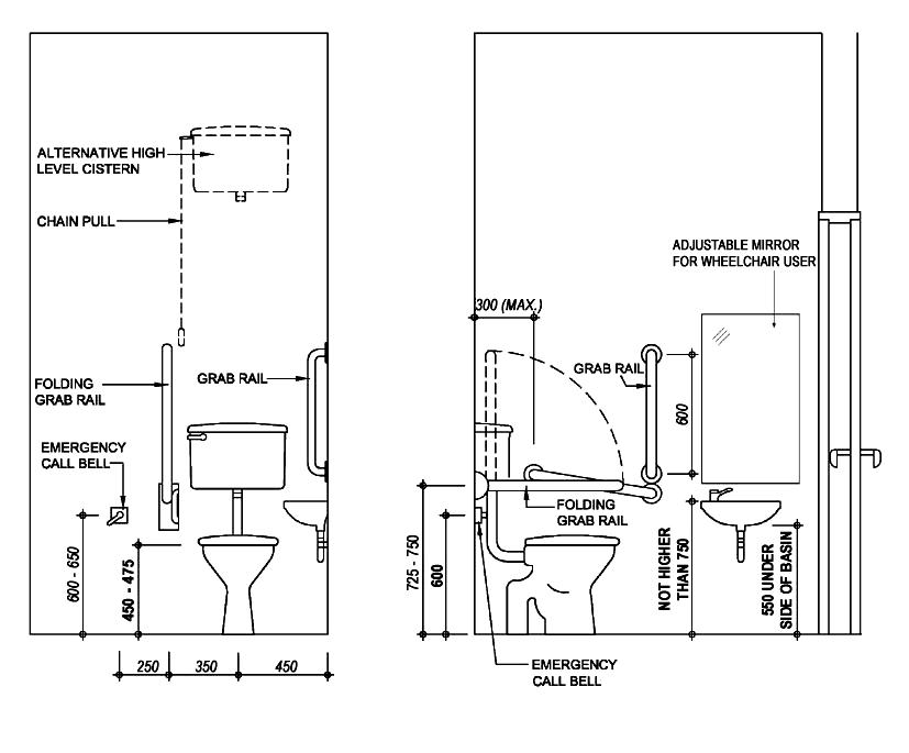
Flushing control shall be mounted on the wide side of the cubicle at a height between 600 mm to 1050 mm above the finished floor level and shall be hand-operated or automatic. Hand-operated controls shall be capable of being operated with one hand and shall not require tight grasping, pinching or twisting of the wrist. The force required shall not be greater than 22 N.
51. Wash Basins
Obligatory Design Requirements (Cont’d)
The toilet shall be provided with a wash basin mounted with the rim not higher than 750 mm above the finished floor level. A clearance of 550 mm shall be maintained from the finished floor level to the bottom of the apron.
Tap for wash basin shall be automatic or of lever control type without spring loading, subject to the approval of the Water Supplies Department. Tap shall not require tight grasping, pinching or twisting of the wrist. The operating force required shall not be greater than 22 N.
48.
Where toilet is provided on a floor, at least one shall be designed as an accessible unisex sanitary facility for use by persons of both sexes and access to which does not necessitate traversing an area reserved for one sex only. It shall be designed for general use and include adequate circulation space for wheelchair users in accordance with the obligatory requirements as set out in this Division.
47. Accessible Unisex Toilet
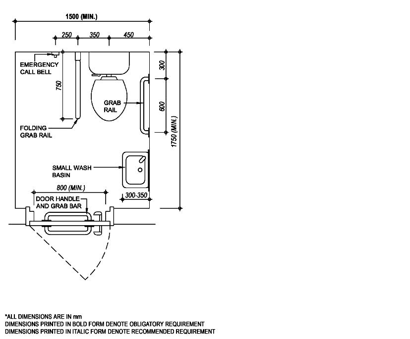
The accessible W.C. cubicle shall not be less than 1500 mm x 1750 mm in area and the clear manoeuvring space within the cubicle shall not be less than 1500 mm x 1500 mm measured at 350 mm above finished floor level and the cubicle shall have in it a watercloset at a height not less than 380 mm and not more than 450 mm, measured to the top of the toilet seat. Waterclosets shall be equipped with a back support such as a seat lid and seats shall not be spring-actuated.
49. Design of Accessible W.C. Cubicle
(ii) where situated within a toilet containing other W.C. cubicles, through a clear space not less than 1500 mm x 1500 mm immediately in front of the compartment to allow manoeuvrability or by direct approach where no turning of the wheelchair is necessary.
62
There shall be one grab rail fixed on each of both the inner and outer surfaces of the cubicle door; which shall not be less than 32 mm and not more than 40 mm in external diameter. The grab rail shall have a grip space of not less than 30 mm clear of each door surface.
grab rail shall not rotate within its fixing fittings.
No coin box shall be affixed to the door of the cubicle.
Obligatory Design Requirements (Cont’d)
There shall be at least two grab rails which shall not be less than 32 mm and not more than 40 mm in external diameter and shall be fixed on the wall leaving a grip space of not less than 30 mm clear of the mounting wall. The two grab rails constructed in one continuous piece is acceptable. The length of grab rail shall not be less than 600 mm.
54. Emergency Call Bell
An emergency call bell complying with Division 17 shall be provided in an accessible W.C. cubicle.
Door shall be installed with push-type or lever-type handles and capable of being easily opened/closed by one hand. Any door fastening shall be capable of being released from the outside in the event of an emergency.
There shall be one folding grab rail on the wide side of the cubicle adjacent to the watercloset at a height between 725mm to 750mm above the finished floor level when lowered from the wall. Simple instructions in English, Chinese and Braille on how to unfold the rail should be affixed to the wall. The grab rail, folding grab rail and wash basin shall be capable of carrying a static load of 150 Thekg.
53. Grab Rails
52. Toilet / Cubicle Doors
(i) have a clear levelled space of not less than 800 mm wide x 1500 mm deep in front; and
Obligatory Design Requirements (Cont’d)
55. Urinals
If more than one urinal is provided, at least one urinal shall
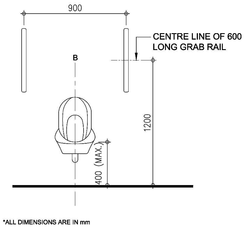
(ii) be wall hung urinal with a front rim not higher than 400 mm, and have vertical grab rails of not less than 32 mm and not more than 40mm in external diameter and of 600 mm length on both sides at a height of 1200 mm above the finished floor level for use by persons with ambulant disabilities. (see Figure 25)
63
64 *ALL DIMENSIONS ARE IN mm DIMENSIONS PRINTED IN BOLD FORM DENOTE OBLIGATORY REQUIREMENT DIMENSIONS PRINTED IN ITALIC FORM DENOTE RECOMMENDED REQUIREMENT FRONT ELEVATION SIDE ELEVATION PLAN (Opposite - Handed Layout is Acceptable) Figure 24 – Accessible Toilet 1500 ( MIN. ) 450-380 750-7251050-900 600 820-750750-725 CLEAR MANOEUVRING SPACE SHALL NOT BE LESS THAN 1500x1500 MEASURED AT 350 ABOVE FINISHED FLOOR LEVEL ANGLE BETWEEN TWO GRAB RAILS 80 - 90 650-600 800 (MIN.) 600 600 (MIN.)1750


(a) Adequate and convenient provision of toileting facilities commensurate with the anticipated use by all users either with or without assistance from others.
65 Figure 25 – Accessible Urinal
A. Design Considerations
mm
(b) Appropriate sanitary accommodation should be available to all, including persons with ambulant disabilities, wheelchair users, the elderly and people of either sex with babies and small children.
BEST PRACTICE SECTION
(c) Provision of a safe environment capable of accommodating the toileting needs and requirements of persons with a disability or the elderly. ARE IN
*ALL DIMENSIONS
(a) W.C. cubicles should, where possible, be unisex and accessible from a corridor so that they can be used by either sex with assistance from members of the opposite sex, if necessary.
W.C. Cubicles
(g) There is a tendency for the specification of sanitary fittings and fixtures to be in white colour to make cleanliness easily observable. Often the fittings are set against light or white coloured tiling which makes clear identification difficult for the persons with visual impairment. Sanitary fittings should have luminous contrast or colour contrast against the background finishes.
Toilet / Compartment Doors
66
B.
(f) Accessible unisex toilet facilities can serve both sexes, those with or without assistance, and accommodate a greater number of users. It is more easily identified than a facility in a separate-sex toilet and more likely to be available when required, particularly as the elderly and some persons with a disability need to use toilets more frequently than others. In addition, a unisex facility enables assistants of either sex to assist the user.
(d) The angle between the two grab rails should be within the range of 80° to 90°
Recommended Design Requirements
Design Considerations (Cont’d)
(e) Urinals should be accessible and can be easily found by persons with visual impairment. The grab rails for aiding the elderly and tactile surface materials for aiding persons with visual impairment should be provided.
(e) Double swing doors which open both inwards and outwards may be provided in any toilets or cubicles. Sliding door is equally acceptable provided that it is not heavy or awkward to use.
(d) If there is adequate space inside the toilet or cubicle units, double swing door open both inwards and outwards or sliding door may be provided to enable assistance during emergency situations.
Unisex Facilities
(b) If two or more accessible unisex facilities are provided, at least one should be of opposite handed layout to the other(s).
(c) The clear distance between the watercloset and the wash basin should not be more than 600 mm for the users’ convenience after toileting. The clear manoeuvring space within the cubicle shall not be less than 1500 mm x 1950 mm.
67
(f) Diaper-changing facilities should be provided in all toilets unless there is absolutely no sufficient space (see Figure 26). Diaper Changing Station
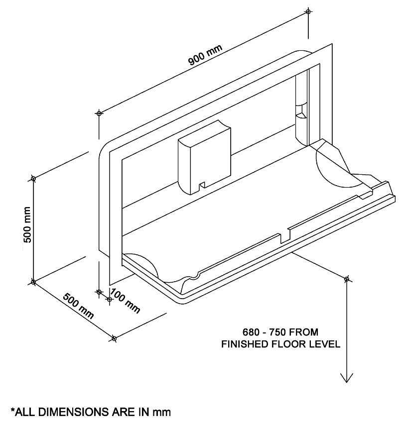
Figure 26 – Flap-type
*ALL DIMENSIONS ARE IN mm
Diaper-changing Facilities
Recommended Design Requirements (Cont’d)
Emergency Call Bell
Luminous Contrast
(i) Waste pipe, disposal bins and other fittings within the toilet should be located to avoid any obstruction or creating a tripping hazard including those under the wash basin.
Large Size Symbols
Bathroom / Shower Compartment
68
(k) An additional emergency call bell near the toilet seat should be provided, if practicable.
(j) Toilets and W.C. cubicles for use by persons with a disability should be located to avoid proximity to or obstruction by exit doors to the staircase.
(g) The floor of the bathroom and the shower compartment should be slip-resistant with a minimum “static coefficient of friction” of “Good” grading (see Appendix C) and self-draining.
(l) Large size symbols with luminous contrast for male and female toilets should be used.
Avoidance of Obstruction
(h) Wall tiling should have a minimum luminous contrast of 30% with sanitary appliances and fittings, grab rails and toilet roll holders, etc.
Recommended Design Requirements (Cont’d)
Obligatory Design Requirements
57. Grab Rails for Bathtub
(2) The bathtub shall be provided with a seat of not less than 250 mm in width (see Figure 27); and
(a) have lever type handles at least 75mm long from the centre of rotation to the handle tip; (b) be installed at the plug end of the bathtub; and (c) be not more than 450 mm above the rim of the bathtub.
This Division sets out requirements for accessible bathrooms and shower compartments as required under paragraph 7 in Division 2.
Division 12 --- BATHROOMS AND SHOWER COMPARTMENTS
(iii) be at least 900 mm long, installed horizontally or slanting at an angle not exceeding 20 degrees along the length of the bathtub and at a height between 150 mm to 300 mm above the rim of the bathtub ; and
Taps and other controls shall: -
(1) There shall be a clear floor space of not less than 1500mm x 800 mm in front of the bathtub (see Figure 27);
Grab rails shall: -
56.
Bathtubs
69
The accessible bathrooms and shower compartments shall be so designed and equipped with sanitary fittings and installations to allow persons with a disability and the elderly to use them without assistance from others.
Performance Objectives
(3) The bathtub shall have a maximum height of 380 mm.
(ii) have a diameter between 32 mm – 40 mm and have a grip space of not less than 30 mm clear from the wall;
(i) not rotate within their fixing fittings;
MANDATORY SECTION
(iv) be at least 600 mm long, installed vertically at the plug end of the bathtub adjacent to the clear floor space with the lower end 150 mm to 300 mm above the rim of the bathtub.
58. Taps and Controls of Bathtub
Thresholds for roll-in shower compartments shall:(a) not be more than 13 mm high; and (b) have bevelled edges.
(1) Shower heads shall:(a) be of the hand-held type; (b) be provided with a hose not less than 1500 mm in length; and (c) be provided with a wall mounting bracket to allow use in a fixed position.
Grab rails for shower compartments shall:(i) comply with paragraph 57 (i) and (ii); (ii) be L-shaped or two bars arranged in L-shaped configuration and not be less than 750 mm by 900 mm in length; (iii) be installed at a height between 700 mm and 800 mm from the shower floor; and (iv) be capable of carrying a static load of 150kg.
Obligatory Design Requirements (Cont’d)
Shower compartments shall have internal dimensions of not less than 1500 mm x 900 mm. The minimum clear floor space in front of the shower entrance shall be 1500 mm x 800 mm with the 1500 mm dimension parallel to the shower entrance.
70
61. Grab Rails for Shower Compartments
60. Shower Compartments
62. Thresholds
(2) Where shower heads are mounted on a vertical bar, the bar shall:(a) have a minimum length of 500 mm with the lower end not less than 450 mm above the finished floor level; (b) be installed so as not to obstruct the use of grab rails referred to in paragraph 57; and
(c) be so mounted to be able to carry a static load of 150kg in case they are mistakenly used as a grab rail.
59. Shower Heads
63. Shower Seats
Obligatory Design Requirements (Cont’d)
A. Design Considerations
71
BEST PRACTICE SECTION
The shower seats shall:(i) have a rounded edge and be self-draining ; (ii) be installed on the wall next to the taps and controls; (iii) not be less than 550 mm in width and 400 mm in depth; and (iv) be installed at a height between 430 mm and 480 mm from the top of the seat to the finished floor level.
B. Recommended Design Requirements
Taps and other controls should be installed between the centre line and the outer edge of the bathtub.
Wheelchair users generally require larger space for access to the bathrooms. A proportion of guest rooms should be designed to accommodate the need of wheelchair users.
72 Figure 27 - Example of Bathroom and Shower Compartment *ALL DIMENSIONS ARE IN mm (b) SHOWER COMPARTMENT
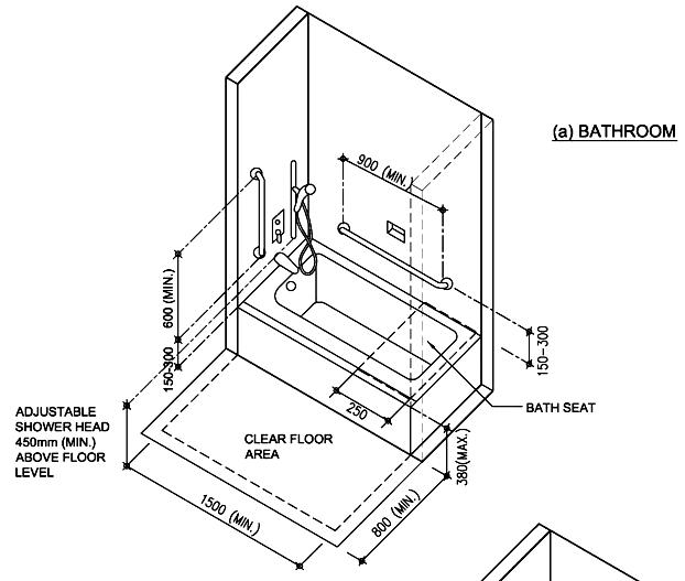
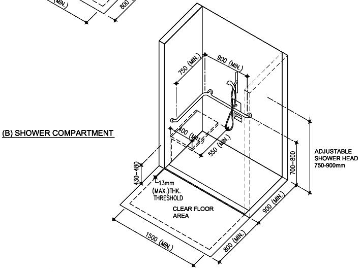
It is essential that suitable signs are erected at prominent and conspicuous positions inside and outside a building to indicate clearly the exact locations of facilities that are available for use by persons with a disability. To design an effective signage system, the needs of different types of users in a building and the complexity of the building layout must be considered.
64. The International Symbol of Accessibility
Obligatory Design Requirements
Signs shall give clear directions, information and instructions for the users of the building.
The international symbol of accessibility shall be the wheelchair figure in white on a blue background and is to be provided at conspicuous location as shown in Figure 28 for the purposes of identifying/advertising /signifying:
Figure 28 – Proportional Layout for International Symbol of Accessibility
Signs shall be erected to indicate clearly the exact locations of facilities available for use by persons with a disability.
Division 13 --- SIGNS
73
MANDATORY SECTION Performance Objectives
(a) accessible entrance to the building; (b) accessible exit from the building; (c) reserved car parking facilities for persons with a disability; (d) the location of toilets for persons with a disability; (e) usable vertical circulation facilities; (f) usable cloakroom facilities; and (g) the availability of special services of information / service counter and telephone in the building.
Gridlines are provided to GRIDLINEStheproportiononlyhowARESHOWN TO DEFINE THE PROPORTION ONLY
(B) EXAMPLE OF A SIGN IDENTIFYING A FACILITY AND INDICATING ITS DIRECTION USING A WORD
The height of signs shall be not less than the following : 60 mm for doors 110 mm for corridors 200 mm for external use
66. Size
Directional arrows and visual information shall be provided at conspicuous location in conjunction with the international symbol for accessibility to guide persons with a disability to the exact locations of the accessible facilities. (see Figure 29) 29 – Directional Signs
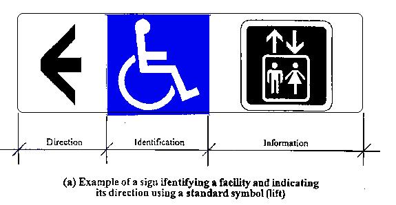

Figure
65. Directional Signs
DIRECTIONDIRECTION IDENTIFICATIONIDENTIFICATION INFORMATIONINFORMATION
Obligatory Design Requirements (Cont’d)
(A) EXAMPLE OF A SIGN IDENTIFYING A FACILITY AND INDICATING ITS DIRECTION USING A STANDARD SYMBOL [LIFT]
戲院 Theatre
74
67.
75
Sign for Persons with Hearing Impairment
Figure 30 – Proportional Layout for International Symbol of Access for Hearing Loss
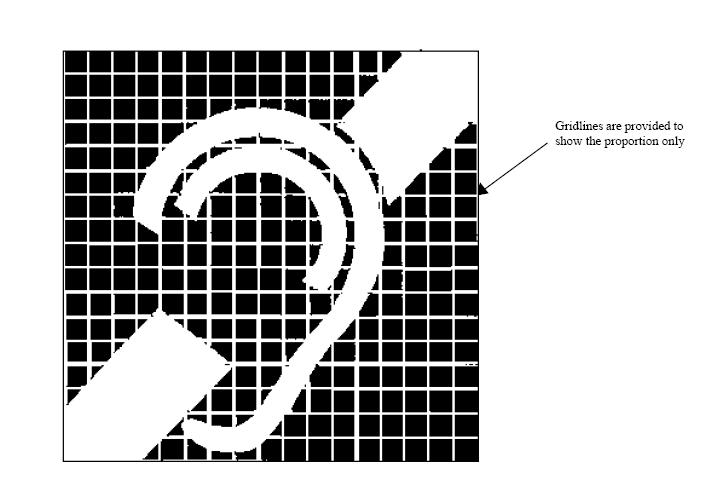
Obligatory Design Requirements (Cont’d)
International symbol of access for hearing loss as shown in Figure 30 shall be provided if there is an assistive listening system provided for persons with hearing impairment.
GRIDLINES ARE SHOWN TO SHOW THE PROPORTION ONLY
Obligatory Design Requirements (Cont’d)
(3) If there is no door, the sign shall be provided on the wall in front of the toilets.
Figure 31 – Specification of Braille Cells
76
68.
Braille and Tactile Sign
(4)&(5) A Braille and tactile fire exit map as shown in Figure 32 shall be provided directly above the call button of the accessible lift in the lobby of the accessible lift in a building if a fire exit map for the use of the public is provided. The map shall be placed at 800 mm to 1200 mm above the finished floor level.
(1)&(2) Braille and tactile sign shall be installed on adjacent wall or door of public toilet to indicate whether the toilet is for male, female or unisex. The sign shall be placed at 900 mm to 1500 mm above the finished floor level. Specification of Braille cells is shown in Figure 31.
Braille information
Note: The 2m and 5m as shown on the Map are hypothetical figures only. They shall be subject to actual site condition.
69. Special Design Requirements to assist persons with visual or hearing impairment
Figure 32 – Braille and Tactile Fire Exit Map
(1) This paragraph applies to any part of a building used for the purposes as specified in Table 2 in Chapter 2.
(2) If a floor plan for the use of the public is provided, Braille and tactile floor plan showing the main entrance, public toilet and major common facilities shall be provided in a place in that building which is conspicuous to persons with visual impairment.
77
(3) Tactile guide path shall be installed from a point of access at the lot boundary to the main entrance of the building and from the main entrance to lift zone, the nearest accessible toilet, public information/service counter, Braille and tactile floor plan and staircase as illustrated in Figures 33, 34 and 35 respectively.
(4) If visual display board (such as LED) is provided, it shall be able to display the essence of the information broadcasted by the public address system in the building. Examples include display boards to inform travellers of the arrival and destination of the MTR trains.
Division 14 --- Special Obligatory Design Requirements to Assist Persons with Visual/Hearing Impairment to Various Uses of Buildings in Table 2
DIAMETERNOMINALRAISEDTILE/BLOCKPOSITIONALTACTILEWITHDOTSOF23mmATBASE
Figure – Tactile Guide Path to Lift Zone
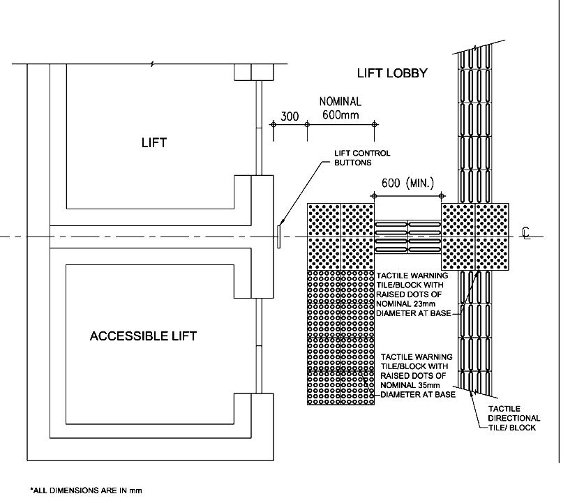
33
78
*ALL DIMENSIONS ARE IN mm
Braille Directory Map
TACTILE
35
*ALL DIMENSIONS ARE IN
Floor Plan
mm
79
Figure – Tactile Guide Path to Tactile / /
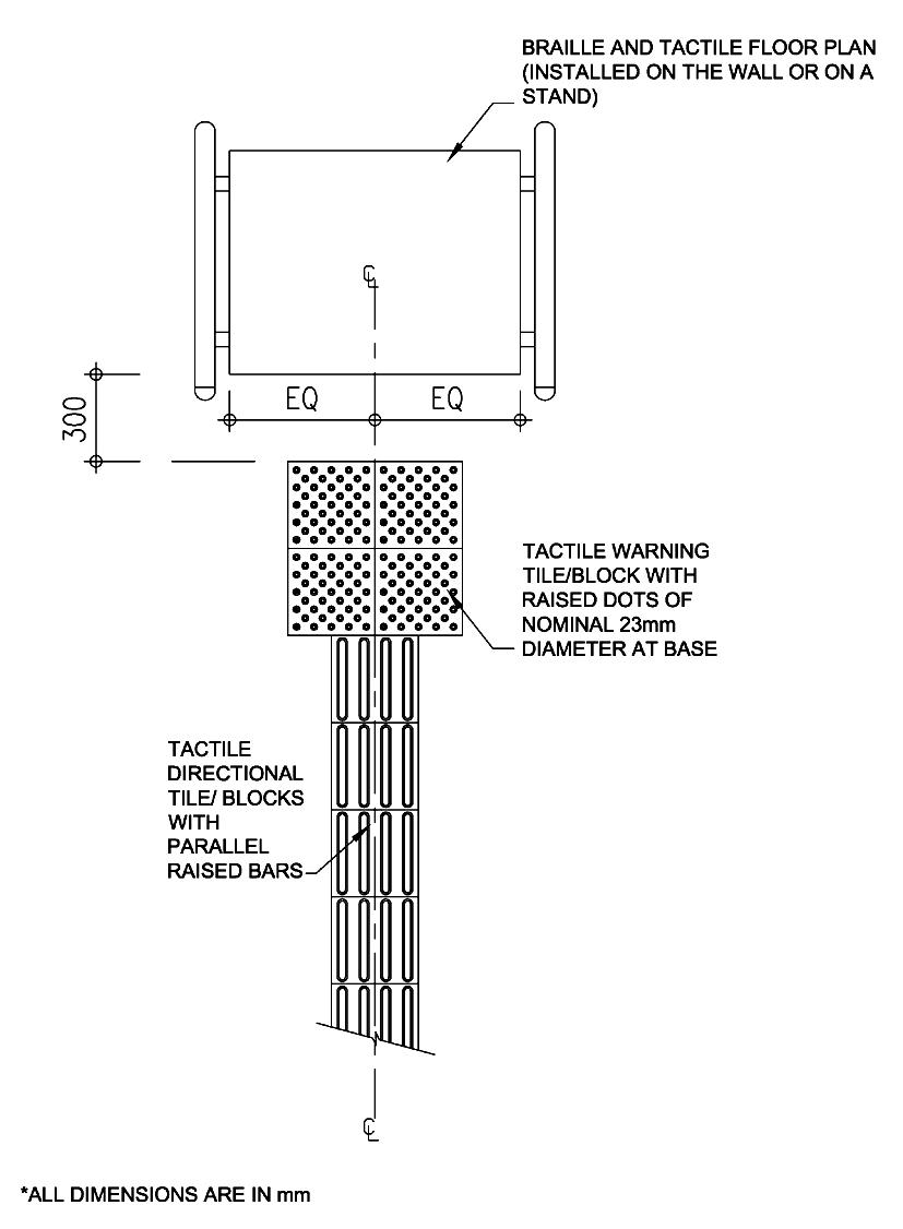
DIAMETERDOTSTILE/BLOCKTACTILEDIAMETERDOTSTILE/BLOCKPOSITIONALWITHRAISEDOFNOMINAL23mmATBASEPOSITIONALWITHRAISEDOFNOMINAL23mmATBASE
*ALL DIMENSIONS ARE IN
mm
Figure 34 – Tactile Guide Path to Information / Service Counter
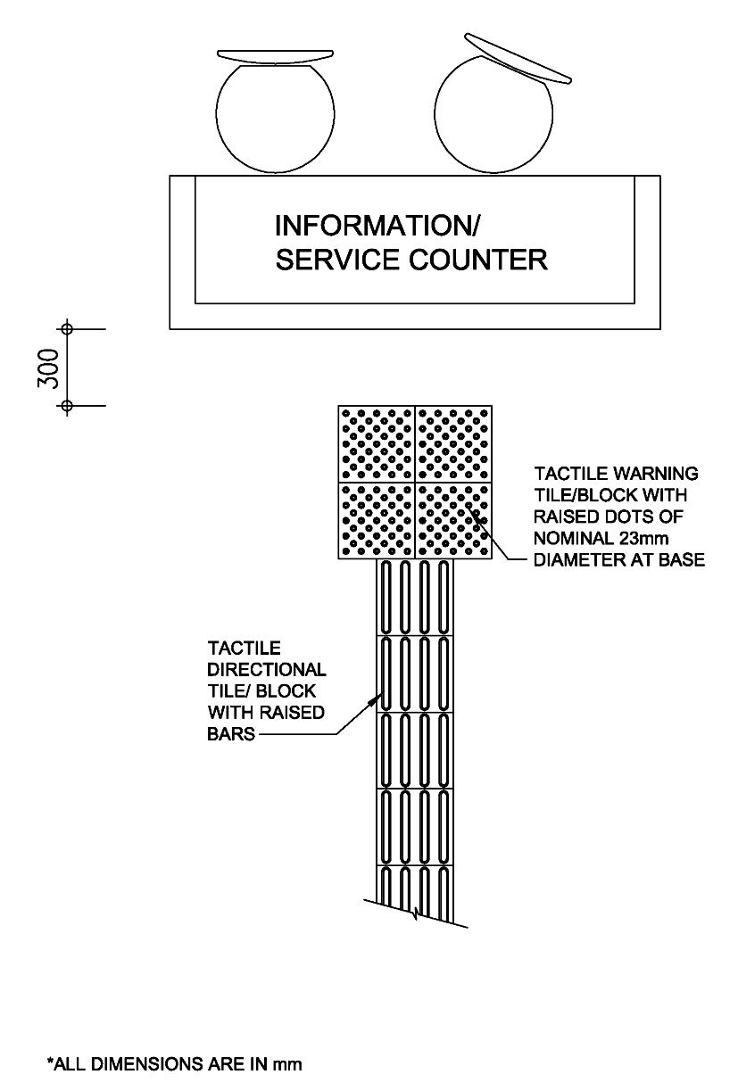
Figure 36 – Tactile Warning Strip to Escalator or Passenger Conveyor CONVEYOR) CONVEYOR)
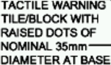


80
(PASSENGER
*ALL DIMENSIONS ARE IN mm (PASSENGER
(f) For categories of buildings as required in Table 2 in Chapter 2, tactile guide paths should be provided for persons with visual impairment from the main entrance to lift zone, public information/service counter, Braille and tactile floor plan, and staircase/escalator provided with audible signals. Braille and tactile floor plan showing the locations of major common facilities should be provided in a location in that building which is conspicuous to persons with visual impairment.
A. Design Considerations
81
BEST PRACTICE SECTION
(c) Prominent signs with high color and luminous contrasts as well as special shapes are recommended to be used for the elderly.
(e) To account for persons with visual impairment, larger fonts, more prominent and well-defined shapes of signs are recommended.
(a) Signs should be clear and easy to read and understand in order to assist persons with intellectual, cognitive and sensory disabilities.
(d) Safety for persons with visual impairment should be considered. Information such as distance to the destination, name of building etc. should be conveyed to the persons with visual impairment. The suggested provisions are voice message, Braille and signs with high luminous contrast.
(b) International symbols are to be used for purpose of standardization and apprehension by all persons with a disability residing in Hong Kong or visiting from overseas. Examples of standard public information symbols are shown in Figure 37.
Luminous Contrast
B. Recommended Design Requirements
(b) Luminous contrast of not less than 70% should be provided to differentiate the international symbol of accessibility from the background, either light-on-dark or dark-on-light. The commonly employed colours are white for the wheelchair figure and blue for the background.
82
Figure 37 — Examples of Public Information Symbols
(a) Sign should be erected to indicate clearly the locations of accessible routes through the building.
Location
(g) The system of sign used should be clear and consistent.
(j) If a floor plan for the use of the public is provided, Braille and tactile floor plan with audible device indicating the main entrance, public toilet and major common facilities should be provided in a place in that building which is conspicuous to persons with visual impairment.
(c) Lettering should be plain and legible, e.g. Helvetica (medium) using lower case letters except for initial capitals.
(i) If public address system is provided to convey information to the public in a building, then a means of conveying the same or equivalent information to persons with hearing impairment should also be provided.
83
Braille and Tactile Sign / Audible Sign
Visual Sign
(f) Sign should be in raised characters.
(h) Braille and tactile building name and address (i.e., street name with number) or a device which when activated will provide the same information in audible form should be provided on both sides of the building entrance at a height of between 900 mm and 1500 mm above the finished floor level.
(d) Corners of sign should be rounded.
Recommended Design Requirements (Cont’d)
(k) Visual display board (such as LED) should be provided in public waiting areas other than those required in Table 2 in Chapter 2 and where there is an announcer installed to regularly convey information to the people inside. The visual display board should be able to display the essence of the information so announced.
(e) Chinese characters should be legible e.g. “Haak Tai” style.
Lettering and Colour
(1) Public information/service counters shall be provided to various categories of buildings as specified in Table 2 in Chapter 2.
(2)(a) There shall be at least one public information/service counter built with a portion not higher than 750mm above the finished floor level and not less than 750 mm wide to assist wheelchair users (see Figures 38 and 39).
(b) There shall be at least one public information/service counter provided with an assistive listening system where the background is noisy or counters are provided with screen.
71. Design of Counter
(1) Where public information/service counters are provided, they shall be accessible and easily identifiable from a building entrance by all persons with or without a disability.
84
(2) Leg space of a depth between 400 mm – 600 mm and a height of not less than 680 mm above finished floor level shall be provided.
Information/service counters refer to provisions for assistance in a building where the public or a section of the public is likely to approach to seek services and/or information.
Division 15 --- PUBLIC INFORMATION OR SERVICE COUNTERS
70. Provision of Public Information or Service Counters
MANDATORY SECTION
Obligatory Design Requirements
85 Figure 38 - Front View of Information / Service Counter for Wheelchair Users *ALL DIMENSIONS ARE IN mm 400-600 )(680MIN.
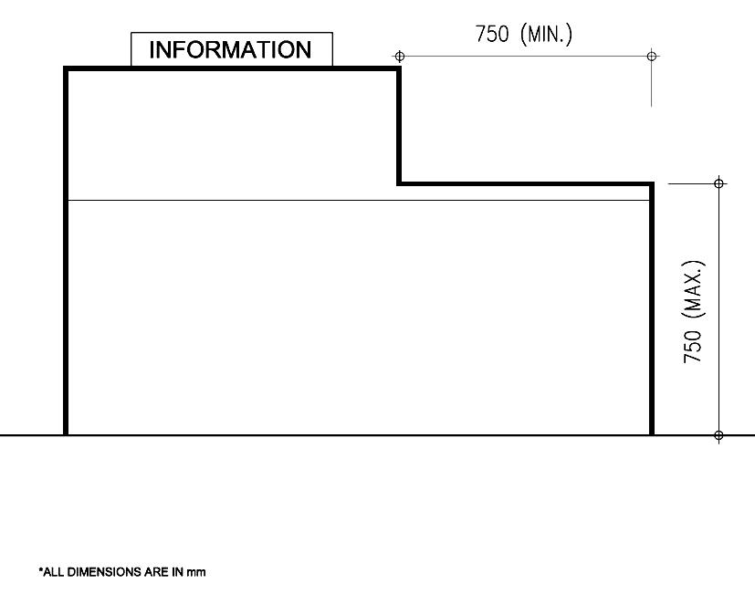
(e) For the convenience of the people using sticks, a recess should be provided to the information/service counter for them to place the assistive tools.
(c) Counters should be located away from the entrance if disturbance of noise from external is anticipated.
86 Figure 39 – Key Heights of Counters and Reception Desks
*ALL DIMENSIONS ARE IN mm
(d) Provision of permanent or temporary control barriers for queuing should allow space for manoeuvring of wheelchairs.
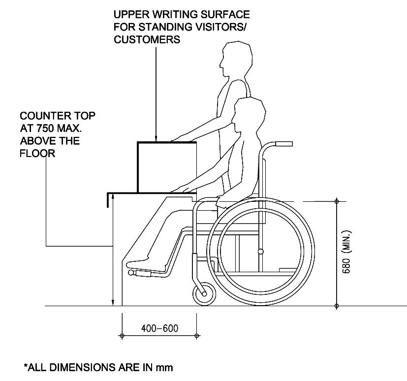
(b) Signs associated with counters should be located and visible to wheelchair users.
A. Design Considerations
(a) The approach to the counter should be direct, clear and unobstructed.
BEST PRACTICE SECTION
74. Means of Provision of Illumination
72. General Illumination Level
Obligatory Design Requirements
The illumination may be provided through automatic or manual switching devices.
A. Design Considerations
87
(b) Where appropriate, lighting should be so designed to illuminate the face of a person speaking in order to make communication easier.
BEST PRACTICE SECTION
Sufficient level of illumination shall be provided in order to help people to apprehend the physical environment of the space they have entered or to move around safely.
Ground floor entrance lobby and lift 120 lux Lift lobby of upper floors, corridors, accessible paths and stairscases 85 lux
(a) Artificial lighting should be designed to give uniform illumination and good colour rendering of all surfaces, without creating glare, or pools of bright light and strong shadows.
73. Illumination Level for Signs
Signs provided under Division 13 shall have illumination level on the sign surface of not less than 120 lux.
The following designated areas of a building, where reasonably expected to be used by the public or occupants of the building during the period of normal use or occupation or when required, shall have minimum illumination level measured at the finished floor level along the centre line of the passageway as follows: -
Performance Objectives
MANDATORY SECTION
Division 16 --- ILLUMINATION
This Division sets out the requirements for lighting provisions.
B. Recommended Design Requirements
(c) Uniformity of illumination level should be maintained throughout the designated confined areas such as staircases, corridors or the like.
Common Areas
(d) Higher illumination level at the entrance doors to flats and the exit doors should be provided.
Illumination Level
88
(b) Lighting with lower illumination level should be provided at the entrances and exits to provide a contrast between the treads and the risers.
(a) Common areas of a building should have an illumination level of not less than 120 lux measured at the finished floor level.
Lighting for Steps
MANDATORY SECTION Performance Objectives
The push button of the emergency call bell shall be appropriately located and conveniently accessible to all users. The emergency call bell when activated shall emit audible or visible alarm signal which shall be readily noticeable for summoning assistance for the person in the accessible toilet. The alarm shall be installed outside the toilet or a buzzer shall be fitted in the caretaker’s office (see Figure 24).
Division 17 --- EMERGENCY CALL BELLS IN ACCESSIBLE TOILETS
75. Emergency Call Bells in Accessible Toilets
(a) A push button should be easily operated and be provided in any individual accessible toilet compartment or a water closet cubicle designed for the persons with a disability to summon assistance at seated position or on the floor when the person has fallen accidentally. The call button, sometimes equipped with a pull cord of a length between 700 mm to 750 mm should be suitably positioned and reachable not more than 300 mm from floor level.
Obligatory Design Requirements
76. Push Button for Emergency Call Bell
This Division sets out the requirements for provision of emergency call bell in accessible toilets.
(b) In addition to a position outside the compartment or cubicle, the emergency alarm should be connected to a 24-hours manned caretaker’s office.
An emergency call bell shall be equipped with a weatherproof push button for activating the alarm. The push button shall be installed below the vertical grab rail inside the W.C. cubicle adjacent to the water closet at a height between 600mm to 650mm above the finished floor level. A notice “Emergency Call” in both English, Chinese and Braille shall be fitted next to the emergency push button.
BEST PRACTICE SECTION
89
A. Design Considerations
(c) Special-purpose receivers are required by infrared and radio frequency systems while hearing aids equipped with a T-switch are capable of receiving the signal from an induction loop system. Designers should seek expert advice concerning the most appropriate system for their purposes.
77. Assistive Listening System
(a) An assistive listening system amplifies audible communication, and can be used by persons with hearing aids. It does not interfere with the listening of people with normal hearing.
MANDATORY SECTION Performance Objectives
Obligatory Design Requirements
Division 18 --- ASSISTIVE LISTENING SYSTEM
(b) The three assistive listening systems commonly used to provide this enhanced level of sound are induction loop, infrared and radio frequency systems. A decision on which system to use will depend on a number of factors, such as the size and use of the space, external interferences and building materials used.
A. Design Considerations
In order to obtain the full benefit of attending public performances or taking part in discussions, a person with hearing impairment needs to receive a signal that is amplified in both volume and signal to noise ratio.
(b) the hall and auditorium, if any, of such a building.
An assistive listening system is a system which enables sound signals to be transmitted to persons with hearing impairment without interference from background noise or excessive reverberation
(a) at least one of the public information/service counters, if any, for various categories of buildings as specified in Table 2 in Chapter 2; and
90
An assistive listening system (such as an induction loop system or an infrared system) shall be provided in:
BEST PRACTICE SECTION
B. Recommended Design Requirements
The assistive listening system must be available to cover not less than 70% of the floor area of the room or space served by the system. If a system requiring the use of receivers or the like is adopted, a minimum of 2 receivers should be provided. The number of receivers provided must be not less than 1 for every 50 persons (or part thereof).
Coverage
91
92
Lift provides means of vertical transportation to any user of the building to move from one floor to another.
Where a lift is provided, appropriate provision shall be made for all people to travel vertically within the buildings conveniently and independently to other storeys and to make use of all relevant facilities.
Obligatory Design Requirements
Division 19 --- LIFTS
(1) Every floor of a building shall be accessible by at least one passenger lift which shall fully comply with all the obligatory design requirements as stipulated in this section and have direct access to main lift lobby.
A lift shall have minimum internal car dimensions of 1200 mm x 1100 mm wide, with a minimum clear entrance width of 850 mm, and shall have handrails extending to within 150 mm of the corners at the rear and sides of the car. The top of the gripping surface of the handrails shall be at a height of 850 mm – 950 mm, with a space of 30 mm - 50 mm between the handrails and wall. (see Figure 40)
78. Special Requirements for Accessible Lifts
MANDATORY SECTION Performance Objectives
All other passenger lifts in the building must comply with paragraphs 79 & 80.
(2) Where there are more than three lifts in a building, access shall be provided to every floor by at least one lift having minimum internal car dimensions of 1500 mm x 1400 mm (either wide or deep) with a minimum clear entrance width of 850 mm.
93 Figure 40 – Accessible Lift *ALL DIMENSIONS ARE IN mm NOTE: WHERE THE NUMBER OF LIFTS IN A BUILDING EXCEEDS 3, AT LEAST 1 LIFT SHALL HAVE MINIMUM INTERNAL CAR DIMENSIONS OF 1500mm X 1400mm
(1) Lift car doors and landing doors shall be of the horizontally sliding type, power-operated and automatically controlled.
Obligatory Design Requirements (Cont’d)
(3) Provision of secondary control panel for over-spilled floor numbering buttons is always acceptable.
(2) An audible signal shall be provided to signify the closing of the doors to alert persons.
94
(1) Essential lift control buttons including floor numbering buttons, emergency alarm push button and door opening push button in the lift car shall not be less than 900 mm and not more than 1200 mm above the floor of the car.
(5) Braille and tactile markings shall be placed either on or to the left of the control buttons.
80. Lift Control Buttons
(4) All lift control buttons shall have a minimum dimension of 20 mm (see Figure 41).
79. Lift Doors
(4) The detection device shall be positioned at a height of between 500 mm to 600 mm above the floor of the lift car.
(8) The emergency alarm push button shall be in a tactile bell shape (see Figure 41).
(7) The tactile marking of the push buttons for the main entrance floor shall be identified with a symbol in a star shape (see Figure 41).
(2) Lift call buttons at the lift halls shall not be less than 900 mm and not more than 1200 mm above the floor of the finished floor level of the lift hall.
(3) A detection device shall be provided to re-open the lift doors in the event of hitting any obstacle.
(6) Such Braille and tactile markings shall be in Arabic numerals and/or symbols. Tactile markings shall have a minimum dimension of 15 mm high and be raised 1 mm minimum.
Figure 41 – Tactile Graphic for Lift Control Buttons


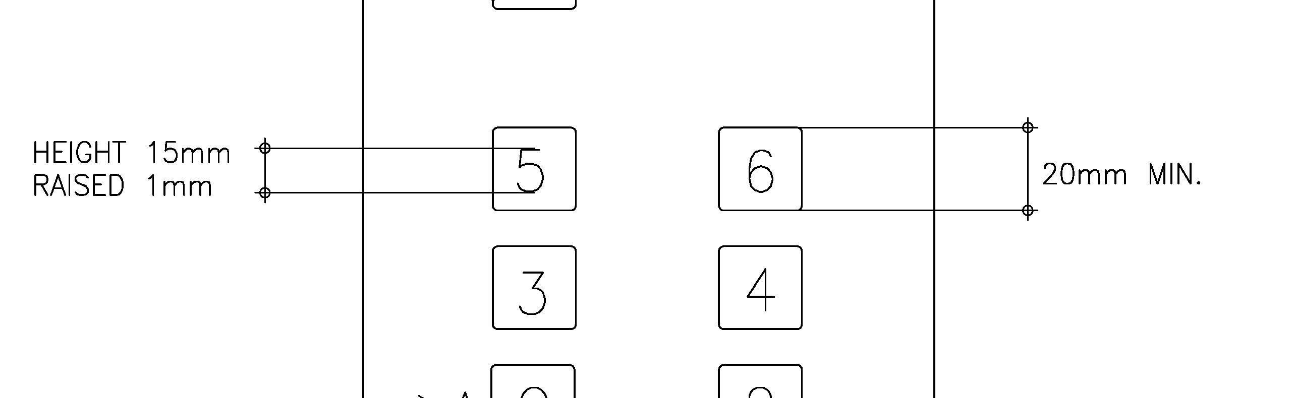


95

96
(i) An emergency alarm push button together with a buzzer, an indication light for acknowledgement and an intercom shall be provided in each lift car and be connected to the building management office or the caretaker’s office. The building management office or the caretaker’s office shall be equipped with a buzzer, indication light(s) (one for each lift) and an intercom connected to the lift car(s).
(ii) The indication light for acknowledgement shall be in the form of a blinking light adjacent to the intercom speaker and a notice “When light blinks, it indicates your emergency call has already been received. Please be patient and wait for the rescue.” in English and Chinese shall be provided next to the blinking light. This system shall be powered by an emergency electricity supply system in the event of power failure.
BEST PRACTICE SECTION
(d) Lift door systems should be designed to allow adequate time for passage of persons with a disability and the elderly.
Obligatory Design Requirements (Cont’d)
Emergency Call Button in Lifts
(b) Lift controls should be installed at the position which is within reach of all users including wheelchair users.
(c) A wheelchair user needs sufficient space and time to enter and leave a passenger lift, particularly when sharing it with other people. Lift sizes should therefore be chosen to suit the anticipated frequency of use of the building and the needs of persons with a disability.
(a) Lifts can help to provide access to storeys above or below the main entrance level. If designed appropriately, lifts are the most convenient form of vertical access for persons with a disability. However, given the space constraints in some buildings, it may not always be possible to install the type and size of passenger lift that would be suitable for use by all, and other options may need to be considered to provide for users with ambulant impairments.
A. Design Considerations
(c) In cases where difficulties are encountered to fully comply with the obligatory requirements of installation of lift control buttons in high-rise buildings, keypad control device in conjunction with a conventional lift control panels in lifts for persons with a disability should be provided. Proposed standardized positions of buttons for keypad control device are shown in Figure 42 for reference.
(f) For lifts of the size that does not allow a wheelchair user to turn around within the lift car, mirror should be installed with the bottom edge to be set at 900 mm above the floor level in the lift car to facilitate a wheelchair user in reversing and to see which level the lift has reached.
Keypad design
Lift Control Buttons
(ii) have Braille and tactile markings following the standard as stipulated in paragraphs 80(6) and 80(8);
Design Considerations (Cont’d)
(iv) have adequate luminous contrast between the tactile markings on the buttons and the background;
(b) Call button panels should be provided at both sides of door openings.
97
B. Recommended Design Requirements
(iii) be installed between 900mm to 1200mm from finished floor level of the lift car;
The keypad should: -
(g) Where planning allows, lift cars may be provided with opposing doors to allow a wheelchair user to leave without having to reverse.
(e) The use of visually and acoustically reflective wall surfaces can cause discomfort for persons with visual and hearing impairment.
(a) The graphics for tactile markings for open-door and close-door push buttons, emergency alarm button, and main entrance level are shown in Figure 41 for reference.
(v) have voice announcement and visual indication of the floors registered; and
(i) have control buttons of minimum dimension of 20 mm;
Recommended Design Requirements (Cont’d)

Figure 42 – Proposed Standardised Position of Buttons for Keypad Control Device
98
(vi) have instruction for the keypad control panel in the form of Braille or voice announcement beside the panel.
Keypad design (Cont’d)

99
(f) The minimum time for lift doors to remain fully open at a landing should be 3 seconds.
Illumination Level
Lift Doors
(e) An unobstructed wheelchair turning space of 1500 mm x 1500 mm should be provided in front of accessible lift car door.
Wheelchair Turning Space
(d) The level of illumination at the car controls, platform, car threshold, landing sill and lift landing shall be 150 lux minimum.
Recommended Design Requirements (Cont’d)
82. Indication in Accessible Lift Cars
81. Indication and Notification for Accessible Lifts
(1) Illuminated visual indicators shall be provided to indicate the direction of travel and the position of the car.
(2) Characters on the position indicator shall have a minimum height of 50 mm.
The requirements for indication and notification to be provided in respect of accessible lifts are set out in paragraphs 81 to 83.
Obligatory Design Requirements
INDICATION AND NOTIFICATION FOR LIFTS COMPLYING WITH DIVISION 19
(1) If a building contains some lifts that do not comply with Division 19, then each of those lifts that do comply shall be identified at each landing served, by not less than one international symbol for accessibility.
(3) An audio indication of the stopping floor shall be provided in English, Cantonese and Putonghua.
100
Indication and notification shall be provided to give audible and visual information to enable all persons with a disability to call and use the lift facilities conveniently and independently.
83. Identification of Accessible Lifts in Lift Lobbies
Tactile and Braille floor designations shall be provided on the jambs on both sides of each lift entrance, by means of Arabic numerals, minimum 60 mm high, raised 1 mm, and at 1200 mm above the finished floor level.
An illuminated visual indicator and an audible signal shall be provided at the lift entrance to indicate the arrival of the lift car and its direction of travel. The audible signal shall sound once for UP direction and twice for DOWN direction, and shall be activated before the arrival of the lift. The audible signal can be broadcasted from a device in the lift car as an alternative provided it can be heard from the lift lobby.
MANDATORY SECTION Performance Objectives
A. Design Considerations
Tactile Warning
(2) If all the lifts in a building comply with Division 19 (including a building with only one lift), then at least one international symbol for accessibility shall be provided at each lift lobby on the entrance levels of the building.
BEST PRACTICE SECTION
101
(a) Tactile warning tiles should be placed in front of the lift door of the accessible lift complying with Division 19 at each landing for ease of identification by persons with visual impairment.
Control
B. Recommended Design Requirements
(b) A separate call button for the accessible lift complying with Division 19 should be installed on each floor to ensure that the accessible lift will stop at the called floor. Priority of attendance to call for the accessible lift should be given to this button.
Signs indicating the location of an accessible lift should be clearly visible from the main entrance of the building. Additionally, a sign identifying the floor reached should be provided on each landing in a location that can be easily seen from the lift and is designed in luminous contrasts with its surroundings.
Obligatory Design Requirements (Cont’d)
85. Tactile Warning Strips
Escalators and passenger conveyors provide means of vertical and horizontal transportation within a building respectively.
Obligatory Design Requirements
(1) Tactile warning strips shall be provided at both bottom and top ends of an escalator. The provision of tactile warning strips is illustrated in Figure 36.
A. Design Considerations
Division 20 --- ESCALATORS AND PASSENGER CONVEYORS
(c) Adequate distance for horizontal movement of steps is required at the top and bottom of escalator to ensure that passengers – especially those leaving the escalator – have adequate space and time to board and alight safely.
Performance Objectives
MANDATORY SECTION
(2) Tactile warning strips shall be provided at both ends of a passenger conveyor. The provision of tactile warning strips is illustrated in Figure 36.
Escalators or passenger conveyors are not considered part of a barrier-free route of travel. However, adequate warning or guarding shall be provided alongside and at each end of the escalators and passenger conveyors for the safety of persons with visual impairment.
102
(a) Escalator can be a useful addition to stair and lift where significant height difference has to be negotiated, but it should be designed with slower speed for the safety use by persons with visual impairment and the elderly.
(b) The angle of inclination of escalator should not exceed 30°
84. Requirements for Escalators and Passenger Conveyors
BEST PRACTICE SECTION
Design Considerations (Cont’d)
B. Recommended Design Requirements
(g) The same principles of luminous contrast as for escalator should apply to passenger conveyor.
(a) For escalator and passenger conveyor, clear signal or indication for going up / down or moving forward should be provided on both ends, e.g. consistent clear sound or signals.
Alternative Access
(b) Where there is an accessible lift that provides alternative access route for persons with a disability, it should be near to, and clearly shown by a sign posted at the entry to the escalator.
103
Audio Indicator
(h) There must always be an alternative pedestrian route provided.
(f) Passenger conveyor may be used when there is substantial traveling distance between pedestrian entrance and vehicular access point, e.g. in an airport terminal. It is mechanically similar to escalator which may be level or inclined.
(d) Step edge should be clearly defined with colour in sufficient luminous contrast with the background, e.g. yellow colour against dark grey steps.
(e) Moving handrail should be in luminous contrast with the background.
A. Design Considerations
(a) Ease of operation, visibility, reachable height and free from obstruction are key factors that affect the use of building services by persons with a disability.
(c) Switches close to the floor or skirting are difficult to reach and dangerous because the users have to stoop or kneel to operate them. The higher the socket outlet, the easier it is to push in or pull out the plug. However, there may be exceptions to height requirements for some socket outlets, e.g. those set into the raised flooring in open plan offices.
BUILDING SERVICES DESIGN REQUIREMENTS
104 CHAPTER 5
(b) All outlets, switches and controls should be positioned consistently in relation to doorways and corners within a building and in a logical sequence of passage through the building.
Switches, socket outlets and controls for lighting and other equipment shall be located so that they are easily reachable for all users.
(a) Except as otherwise provided in Division 19 for lifts, the controls for the operation of building services or safety devices including electrical switches, light switches, thermostats, intercom switches and card reading machines which are intended to be accessible to wheelchair users should be located between 450 mm and 1200 mm above the finished floor level (see Figure 43).
This paragraph is applicable to operable part of controls such as electrical switches, wall socket outlets and controls of other electrical and mechanical equipment.
B. Recommended Design Requirements
(e) To cater for persons with visual impairment, controls should be in colour and luminous contrast with the background, and with embossed information on them for tactile reading.
Positioning
5.1 SWITCHES AND CONTROLS
(d) Operation of controls intended to be used by persons with a disability should not require the use of both hands simultaneously.
BEST PRACTICE SECTION
Recommended Design Requirements (Cont’d)
(b) Electric sockets should be located not lower than 450 mm above the finished floor level.
Figure 43
105
Positioning (Cont’d)
(c) Light switches and socket outlets should have a minimum luminous contrast of 30% with their background to indicate their locations.
Luminous Contrast
(d) Controls should: (i) have a minimum luminous contrast of 30% with the background finishes; (ii) not require tight grasping or twisting; (iii) be visible from a seated position; and (iv) not be of small button type. – Heights of Switches and Controls
Controls
*ALL DIMENSIONS ARE IN mm 450
5.2.1 Persons with hearing impairment depend on visual cues to alert them of emergencies. Persons with hearing impairment may need a visible as well as audible alarm which is only sufficient to deliver warning to a normal person.
MANDATORY SECTION
5.2.2 Performance Objectives
Department store and complexshopping
5.2.3 Obligatory Design Requirements
(a) Subject to paragraph (b), visual alarm signal shall be provided to form part of the fire alarm system in the form of a flashing red light, labelled “Fire Alarm 火警” in both English and Chinese. It shall be indicated on separate plate affixed nearby or engraved on the light cover. The alarm shall be installed at a prominent location which shall be readily noticeable when activated in the categories of buildings as specified in Table 2 in Chapter 2.
106
Hotel, guesthouse, hostel and bank -areas not accessible to guests, customers, visitors, e.g. kitchens, plant rooms, staff toilets, offices, back of house facilities, etc.
Where fire alarm systems are provided in areas of a building required to be accessible, the alarm shall emit both audible and visible signals.
-areas not accessible to customers, visitors, e.g. offices, store rooms, plant rooms, staff toilets, etc.
Office -areas accessible to staff only, e.g. offices, store rooms, plant rooms, staff toilets, etc.
5.2 FIRE ALARM SYSTEMS
(b) The provision of visual alarm shall not apply to all exit staircases as required under the Code of Practice for the Provision of Means of Escape in Case of Fire including the smoke lobbies adjoining the exit staircase, and the following areas: -
Place for worship -areas not accessible to worshippers, visitors, e.g. offices, staff toilets, etc.
Domestic use -domestic units
Visual Alarm
Restaurant and food court -areas not accessible to customers, visitors, e.g. offices, kitchens, store rooms, plant rooms, staff toilets, etc.
Cinema, theatre, concert hall, stadium, museum, theme park and centrefamilypurpose-builtamusement
Obligatory Design Requirements (Cont’d)
-areas not accessible to patients, inmates, visitors, e.g. kitchens, plant rooms, staff toilets, offices, laboratories, back of house facilities, staff quarters, etc.
Club House -areas accessible to staff only, e.g. offices, kitchens, store rooms, plant rooms, staff toilets, etc.
-areas not accessible to the visitors, spectators, audience, e.g. projector rooms, offices, store rooms, plant rooms, staff toilets, etc.
107
Indoor market and supermarket -areas not accessible to customers, visitors, e.g. offices, store rooms, plant rooms, staff toilets, etc.
Carpark -areas not accessible to customers, visitors, e.g. shroff offices, store rooms, plant rooms, staff toilets, etc.
Transport passengerinterchange,station,terminal -areas accessible to staff only, e.g. plant rooms, station offices, regulator’s offices, staff toilets, etc.
Sports complex and public swimming pool complex -areas not accessible to visitors, athletes, spectators, e.g. plant rooms, offices, store rooms, staff toilets, etc.
Visual Alarm (Cont’d)
Factory, workshop and place for industrial use
purpose-builtHospital, clinic, residential home for the elderly and welfare centre
-areas accessible to staff only, e.g. offices, store rooms, plant rooms, staff toilets, etc.
School, universitycollege, -areas accessible to staff only, e.g. offices, store rooms, plant rooms, staff toilets, staff quarters, etc.
Audible Alarm
108
(d) Audible alarm shall comply with the requirements of the Code of Practice for Minimum Fire Service Installations and Equipment and the Code of Practice for Inspection, Testing and Maintenance of Installations and Equipment published by the Director of Fire Services.
Obligatory Design Requirements (Cont’d)
A. Design Considerations
Audible and visual alarm may not be appropriate for use in hospitals and some specialized medical facilities, such as operating rooms, where it is not intended to alert or alarm patients who are incapable of independent evacuation. The sudden strobe flash might disrupt a surgical operation in progress which could be catastrophic. For such facilities, the requirements for visual and audible alarm may be modified to suit the norm of industry-accepted practices.
Positioning of Call Points
BEST PRACTICE SECTION
(c) The manual fire alarm call points or activation controls, e.g. breakglass units, in places which are intended to be accessible to wheelchair users, shall be positioned at prominent and accessible locations and installed in accordance with the Code of Practice for Minimum Fire Service Installations and Equipment and the Code of Practice for Inspection, Testing and Maintenance of Installations and Equipment or Fire Services Department Circular Letter.
109 5.3
Public telephones should be accessible by all users, including wheelchair users and persons with visual or hearing impairment.
PUBLIC TELEPHONES
(c) The provision of a text phone enables person with hearing impairment to make calls.
(a) The keypad of a public payphone, if provided with mechanical keypad, should have a digit 5 indicator (see Figure 44).
A. Design Considerations
(a) Telephones should be fixed at an appropriate height which is within easy reach and easy to use, to enable all users, including persons with a disability to make full use of them.
Keypad
BEST PRACTICE SECTION
This paragraph sets out the requirements for telephones intended to be used by the public.
B. Recommended Design Requirements
(b) Other helpful features which should be provided include support rails; adequate lighting; seats; big buttons; lamp signaling; amplifying handset; inductive coupler; speakerphone; and digit 5 indicator.


Figure 44 – Digit 5 Indicator

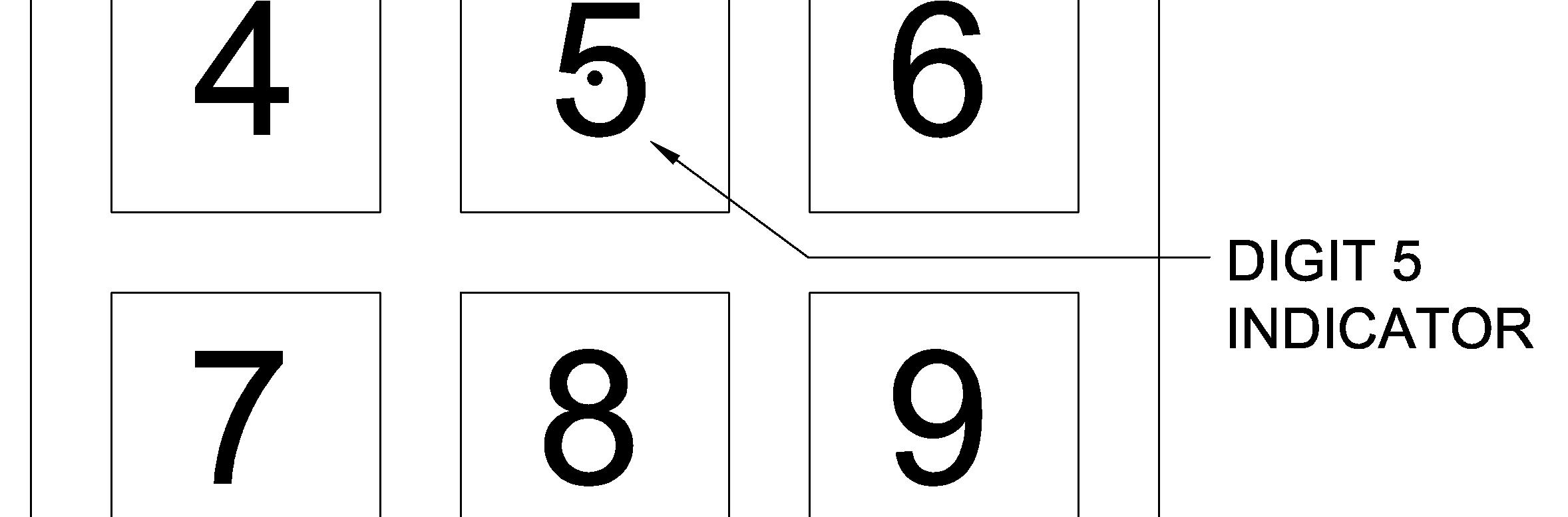
(b) At least one in a group of two or more payphones should be designed for access by persons with a disability and in compliance with the following: -
Recommended Design Requirements (Cont’d)
(ix) if the accessible payphone is provided in an enclosed booth, the door of the booth should open outwards and have a clear width of not less than 800 mm between the open door and the opposite jamb or the other leaf; and
(ii) the accessible payphone should not be placed on a stepped base unless a ramp in compliance with Division 5 is provided;
110
(i) the approach to the accessible payphone should be free of obstacles;
(x) if the accessible payphones are provided in a booth without door, the entrance to the booth should not be less than 800 mm wide.
(viii) If a forward approach is adopted, the enclosure, if any, should have a clear width of at least 800 mm to provide wheelchair access; shelves or other obstructions should not extend more than 400 mm from the face of the accessible payphone; and there should be a space of 750 mm wide by 650 mm high by 430 mm deep for the footplate of a wheelchair;
(vii) if a parallel approach is adopted, the enclosure sides, if there is an enclosure, should not extend more than 250 mm in front of the face of the accessible payphone;
(iv) to facilitate wheelchair users, all operable parts including the coin slot of the accessible payphone should not be positioned higher than 1200 mm above the finished floor level;
(v) if there is an enclosure for the accessible payphone, the enclosure should begin no more than 650 mm from the finished floor level to prevent it from being a hazard to persons with visual impairment;
(c) Grab rails should be installed on each side of the accessible payphone booth to enable those on crutches or with canes to maintain balance while using the accessible payphone. Otherwise, there should be a space of not less than 900 mm in width in the phone booth for persons with a disability to enter with their crutches and canes.
Telephone for Persons with Ambulant Disabilities and Wheelchair Users
(iii) the cord length of the accessible payphone should not be less than 750 mm;
(vi) there should be a clear floor space of at least 750 mm by 1200 mm in front of the accessible payphone to allow either a forward or parallel approach by a wheelchair user;
Telephone for Persons with Hearing Impairment
111
Telephone for Persons with Ambulant Disabilities and Wheelchair Users (Cont’d)
Telephone for Persons with Visual Impairment
(e) At least one in a group of two or more payphones should be designed for access by persons with visual impairment. Such payphone should be provided with a mechanical keypad with the digit 5 indicator and a detection system that activates a recorded sound message, giving explanations on the operational procedures to the users, as the handset is picked up.
(f) Phone cards for payphones should bear a “notch” on the left bottom to aid orientation for persons with visual impairment.
Telephone for Persons With Speech Impairment
(h) At least one in a group of two or more payphones should be capable of handling written messages for access by persons with speech impairment.
(g) At least one in a group of two or more payphones should be provided with amplifying handset or receiver with inductive coupler. If a payphone is equipped with the latter, it should be identified by the international symbol of access for persons with hearing impairment (see Figure 30).
Recommended Design Requirements (Cont’d)
(d) A fold-down seat should be provided in accessible booths for the convenience of persons with ambulant disabilities.
A remote signage system carries and transmits a voice message to the users in the form of a talking sign. The system shall provide audible information to persons with visual impairment who are equipped with proper receivers.
(b) With the hand-held receiver, persons with visual impairment can scan the environment and locate his relative position. It can work effectively in both interior and exterior applications for landmark identification and way-finding.
(a) A remote signage system normally consists of short audio signals sent by invisible infrared light beams from permanently installed transmitters to a hand-held receiver that decodes the signal and delivers the voice message through its speaker or headset.
A remote directional signage system which transmits a voice message by means of infrared or the like detectable by a proper receiver should be provided to facilitate access and movement of persons with visual impairment.
B. Recommended Design Requirements
A. Design Considerations
(c) The system promotes more confident and independent travel throughout all major common areas.
BEST PRACTICE SECTION
112 5.4 REMOTE SIGNAGE SYSTEMS
(iii) minimum size of 1100 mm (wide) x 1400 mm (deep);
(c) It provides access to equipment control rooms and projection booths.
(b) It provides an accessible route to a performing area.
5.5 VERTICAL LIFTING PLATFORMS
A. Design Considerations
A vertical lifting platform is a mechanical lift with a platform and walls which provides vertical circulation between two levels.
A vertical lifting platform shall be designed to facilitate persons with ambulant disabilities and wheelchair users for the vertical transportation from one level to another in a building.
(d) Clear instructions for use and emergency alarm should be provided inside the lifting platform.
(a) Installation of vertical lifting platform is necessary if no other means of vertical transportation is available when the presence of persons with a disability can be envisaged.
B. Recommended Design Requirements
BEST PRACTICE SECTION
113
Door (i) minimum clear entrance width of 900 mm; (ii) Single door or 2-door design; Platform size
(a) Where it is impractical to provide a passenger lift or a ramp, a self-operated vertical lifting platform should be considered as a reasonable alternative for vertical circulation for wheelchair users, the vertical lifting platform should have the following provisions (see Figure 45): -
Safety Barrier
Recommended Design Requirements (Cont’d)
(ix) the maximum travel should be 4000 mm; (x) the rated load of the lifting platform should not exceed 500 kg; and
Control
(viii) grab bars complying with paragraphs 28(3) and (4) in Division 8 should be placed at a height of 900mm from the finished floor level and be fixed on both sides and at the rear of the lift car;
Grab bars
(xii) The landings to a vertical lifting platforms at the 2 access levels should be in opposite directions so as to eliminate the need for the wheelchair to back-out.
(xi) A sign to indicate the rated load should be provided at a prominent position next to the lift control buttons inside the lift; and Landing
Sign
114
(vi) lift buttons should comply with paragraphs 80(1) and (4) in Division 19; (vii) automatic homing device should be installed so that in the event of a power failure, the platform lift will descend to the entrance level;
(iv) provision of safety barriers of not less than 1100mm in height; (v) provision of a flip-up ramp if a door is not provided, to act as a safety barrier and serves as an access ramp for wheelchair users;
Maximum Travel and Loading
115 Figure 45 – Vertical Lifting Platform ElevationPlan *ALL DIMENSIONS ARE IN mm +4.0+4.0MAX.MAX.


Spout
B. Recommended Design Requirements
(c) Facilities for wheelchair users call for extra consideration in relation to access and manoeuvering space.
(a) The design and provision of drinking fountains should take into account the envisaged use of persons with a disability.
A. Design Considerations
BEST PRACTICE SECTION
(a) Where drinking fountains are provided, at least one of the drinking fountains on a given floor should have a design complying with this section.
(c) Automatic controls or controls with handles of the lever type operable with a closed fist should be provided.
(b) The operable controls and direction of water flow should be designed and installed in a manner to facilitate the use by persons with a disability.
(b) The fountain spout should: -
Provision
(i) have an opening located between 750 mm to 900 mm from the floor or ground surface; (ii) be located near to the front of the unit; (iii) direct the water flow in a trajectory that is parallel or nearly parallel to the front of the unit; and (iv) provide a flow of water at least 100 mm high to allow for the insertion of a cup or glass.
This paragraph sets out the requirements for provision of drinking fountains. A drinking fountain is a primary means for providing the public with sanitary water.
5.6 DRINKING FOUNTAINS
116
(d) Controls should:(i) be at or near to the front of the fountain; (ii) be operable with one hand; and (iii) require no tight grasping, pinching, or twisting of the wrist.
117
(e) The spatial arrangement should allow for the provision of:(i) a clear floor space of at least 750 mm x 1200 mm; (ii) a clear knee space of at least 750 mm wide, 200 mm deep and 680 mm high between the bottom of the apron and the floor or ground; and (iii) a toe space not less than 750 mm wide, 230 mm deep and 230 mm high.
Control
Recommended Design Requirements (Cont’d)
(g) A wall guard should be installed to protect a drinking fountain that extends into a corridor and has an open space underneath.
Dimensions relating to the design of drinking fountains are shown in Figure 46.
(f) All wall-mounted drinking fountains should be placed in an alcove to eliminate the hazard of collision to persons with visual impairment.
Spatial Arrangement
(MIN.)230
118 Figure 46 – Built-in Drinking Fountain *ALL DIMENSIONS ARE IN mm
(MIN.)230 230 (MIN.)

DESIGN GUIDELINES FOR THE ELDERLY AND ELDERLY WITH FRAILTY
119 CHAPTER 6
Ageing is a gradual process. The level of ability of a person declines in a progressive manner as ageing progresses. To minimize the potential risks leading to injuries or accidents, the following design guidelines are recommended in consideration of the common habitual actions as well as the declining abilities of many older persons.
Common Habitual Actions of the Elderly Recommended Design Guidelines
6.2.1 The elderly may be unstable in their gait and unable to recognise changes in level of floor surfaces.
6.2 DESIGN CONSIDERATIONS
Steps and staircases should be designed with wider treads and lower Floorrisers.
6.1 GENERAL
Barrier free access should be without steps, thresholds, small ramps or kerbs, wherever possible. Where changes in level are unavoidable, handrails or grab bars should be provided, no matter how slight the level change may seem.
Many aspects of design for persons with a disability are already covered in the Mandatory Sections of this Design Manual and can be usefully applied to the design of both interiors and exteriors of all structures and buildings to make them more friendly to the elderly. The guidelines set out in this Chapter aim to provide additional design recommendations for building a more comfortable, healthy and safe built-environment for older persons.
“Ageing-in-Place” is a universal concept accepted as fundamental to new housing design, the creation of elderly-friendly homes and environment will allow the elderly to enjoy life with autonomy which is essential in achieving the goal of healthy ageing.
surfaces should comply with Division 4. Slip-resistant floor finishes should be used, shiny and reflective floors such as marble, glazed tiles and the like should be avoided.
Double-switching system should be considered. Switches should be installed near to bedside to avoid needing to cross the room in the dark.
wall-mounted light or peripheral lighting from floor lamps are superior to a central ceiling source as the formation of shadows can be Bareavoided.light bulbs producing glare which would cause painful to the aging eyes should be avoided.
Escalators should be designed with slower speed.
All common areas of a building should have an illumination level of not less than 120 lux measured at the finished floor level, and uniformity of illumination level should be maintained for any
Where changes in level are unavoidable, the floor and wall surfaces along the level difference shall be in luminous contrast.
Common Habitual Actions of the Elderly
6.2 DESIGN CONSIDERATIONS (Cont’d)
Alternativespace.
120
Open jointed pavers or aeration paver blocks with uneven or very rough surface should be avoided at external open spaces.
6.2.2 The elderly may be unable to see clearly and may have problems in accommodating dramatic changes of lighting levels.
Recommended Design Guidelines (Cont’d)6.2.1
Consideration should be given to ensure gradual transition of lighting levels from one place to another.
or stand-by light sources should be provided to illuminate any space in case of power failure.
The use of natural lighting or ambient artificial white light should be Theencouraged.useof
Resting places in external recreation spaces should be adequately provided.
Different floor surfaces should be considered for tactile cues for navigation.Auditoryinput at lift helping the elderly to locate themselves should be used.
All interior spaces should be lit at a consistent and even level, from floor to ceiling and from wall to wall. High contrast between shadow and light creating confusion and disorienting patterns should be avoided.
6.2 DESIGN CONSIDERATIONS (Cont’d)
6.2.3 The elderly would have decreased stamina.
Resting places such as fold-down seats on stair landings or in long corridors should be provided.
6.2.4 The elderly may have difficulties in way finding.
Monotonerecommended.colour should be avoided.
Different colours should be used for different floor levels, zonings or areas of different functional purposes.
Recommended Design Guidelines (Cont’d)6.2.2
The colour combination of signageyellow figure on black background or white figure on blue background is recommended.
As the lens thickens and yellows with age, it becomes less sensitive to colours having shorter wavelengths (blues, greens and violets). Warm colours with longer wavelengths (reds, oranges and yellows) are easier to differentiate. The use of the bright primary colour as contrast or highlight is therefore
121
Common Habitual Actions of the Elderly
Control panel or switch at the lift lobby should be located at 1050 mm above the finished floor level. It should be easily operated and havea minimum luminous contrast of 30%.
6.2.6 The elderly may be weak in gripping, and may have difficulties in turning and manipulating taps, switches, door handles and the like.
controls and handles with limited grip should be used. Knob handles, push operated and self-closing type faucet controls should be avoided (see Figure 47).
6.2 DESIGN CONSIDERATIONS (Cont’d)
Handrails should be of materials such as timber or plastic-coated surfaces for easier Lever-typegrip.
Doors of bathrooms and toilets should open outward or both ways. Locks and latches should be of larger sizes and be able to open from outside with a coin.
122
Switches and controls should be installed at reachable heights preferably at the same level as door handles.
Emergency alarm system should be installed. Emergency call bell shall comply with Division 17. Should pull-cord be installed, they must be extended to floor-level.
6.2.7 The elderly may have difficulties in pushing open heavy doors.
Sliding door is a good choice. Should door closing devices be used, they should be designed to allow external and internal doors to be opened with horizontal forces of not more than 28N and 18N respectively.
rack systems with laundry poles should be avoided.
6.2.8 The elderly require safety design provisions for bathrooms and toilets.
Common Habitual Actions of the Elderly
6.2.5 The elderly may fall due to bending, stooping and stretching.
Handrails to corridors, steps and staircases should be lowered to a height between 810 mm and 900mm from the finished floor level to the top of the Cupboardshandrails.
should not be installed at high levels. Overhead cabinets should be Outdooravoided.drying
Recommended Design Guidelines
123
6.2 DESIGN CONSIDERATIONS (Cont’d)
Doorways should be wide enough to allow a wheelchair to pass through and space of bathrooms and toilets should be adequate for turning and transfer.
6.2.9 The elderly built-environment.comfortablerequireandhealthy
Cross ventilation should be optimized in common areas such as corridors and lift Recreationallobbies.
Common Habitual Actions of the Elderly Recommended Design Guidelines (Cont’d)6.2.8
Bathtub should have either built-in seat at the head end or attachable portable seat that fastens securely to the tub when Showers,needed.other
Grab bars should be installed and to comply with Divisions 11 and 12.
or low gloss finishes on floors, matt paint or textured wallpaper on walls should be considered to help reduce glare.Glass or reflective material should be Largeavoided.windows
facilities such as shelters and benches, pavilions and tai-chi areas with safety flooring system should be provided in external open spaces.
than roll-in types, should be of size 1500 mm x 900mm minimum with a folding seat to allow transfer.
Sound-absorbing materials should be used for floors and walls to avoid Non-glareechoes.
should be avoided at the end of long and dark corridors.
Figure 47 – Examples of Door Handles and Faucets
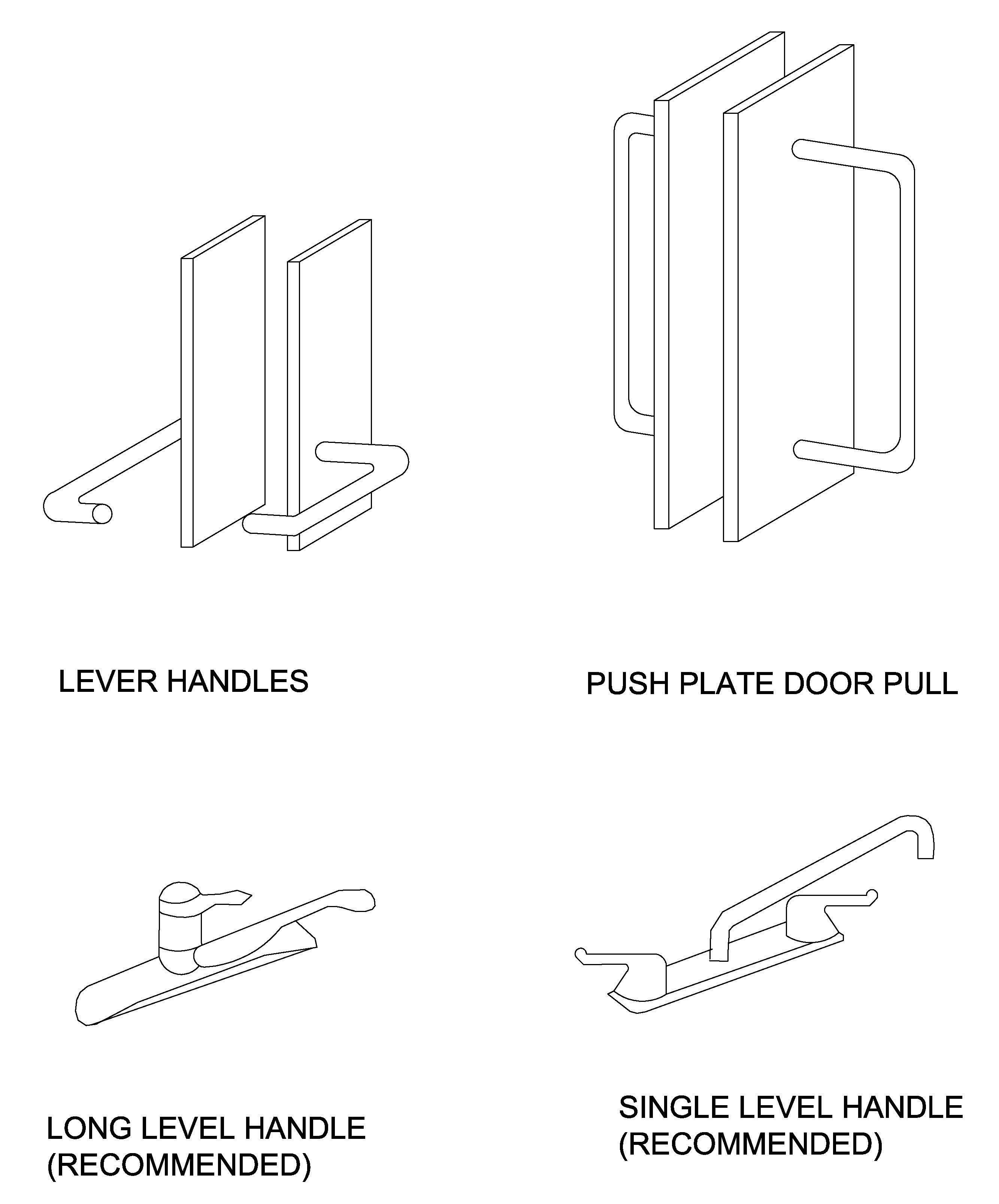
LONG LEVER (RECOMMENDED)HANDLE
SINGLE LEVER (RECOMMENDED)HANDLE
124
PUSH/PULL PLATE DOOR PULL LEVER HANDLES
Appendix AnthropometricsA
Figure A2 - Reaching Zones of an Average Person


A.1 Objective:
Height 1500mm – 1900mm
Max. Reach Up 1850mm – 2100mm
A.2 Considerations:
(All dimensions are in mm)
Figure A1 - Dimensional Data of an Average Person
This Appendix contains dimensional data which can be used for guidance when designing facilities and equipment for use by persons with a disability.
Forward Reach 1300mm – 1450mm
The dimensions of the individual human being vary with time and from one person to another. In addition, the average dimensions vary from one country to another. When carrying out detailed design, consideration should be given to size variation between males and females as well as between different ages.
APPENDIX
Oblique Reach Up 1650mm – 2000mm
Shoulder 1200mm – 1550mm

ANTHROPOMETRICSA


A/1
Eye 1400mm – 1750mm

A/2
Figure A3 - Dimensional Data of a Wheelchair User
Figure A4 - Vertical Reaching Zones of a Wheelchair User
A.3 Forward reach of a wheelchair user


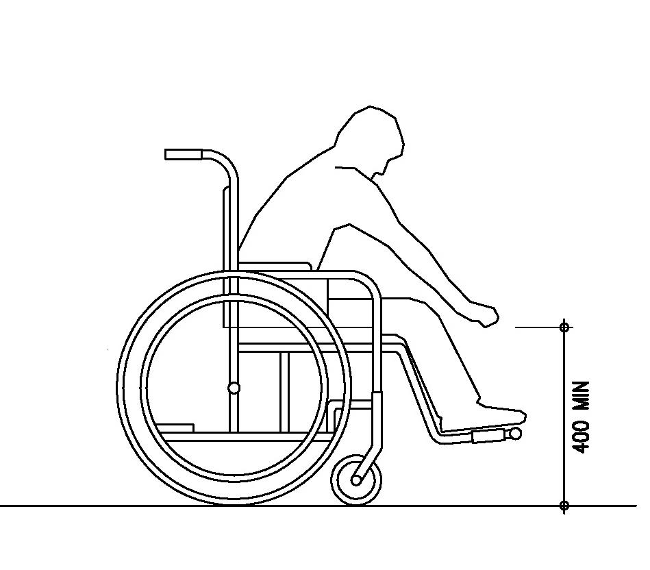

A/3
The maximum forward reach, without obstruction, is 1200 mm from the floor and the minimum forward reach is 400 mm from the floor as shown in Figures A5 and A7.

The maximum forward reach over an obstruction 500 mm deep is 1100 mm from the floor as shown in Figure A6.
Figure A5 - Forward Reach

Figure A6 - Forward Reach Over Obstruction
Figure A7 - Forward Reach Without Obstruction
A.4 Side reach
Obstruction1200MAX
Figure A10 – Maximum Side Reach over an
Figure A8 - Side Reach Without Obstruction
Figure A9 – Maximum Side Reach
The maximum side reach over an obstruction 860 mm high by 500 mm deep is 1200 mm from the floor as shown in Figure A10.
A/4
The maximum side reach, without obstruction, is 1300 mm from the floor and the minimum side reach is 250 mm from the floor as shown in Figures A8 and A9.

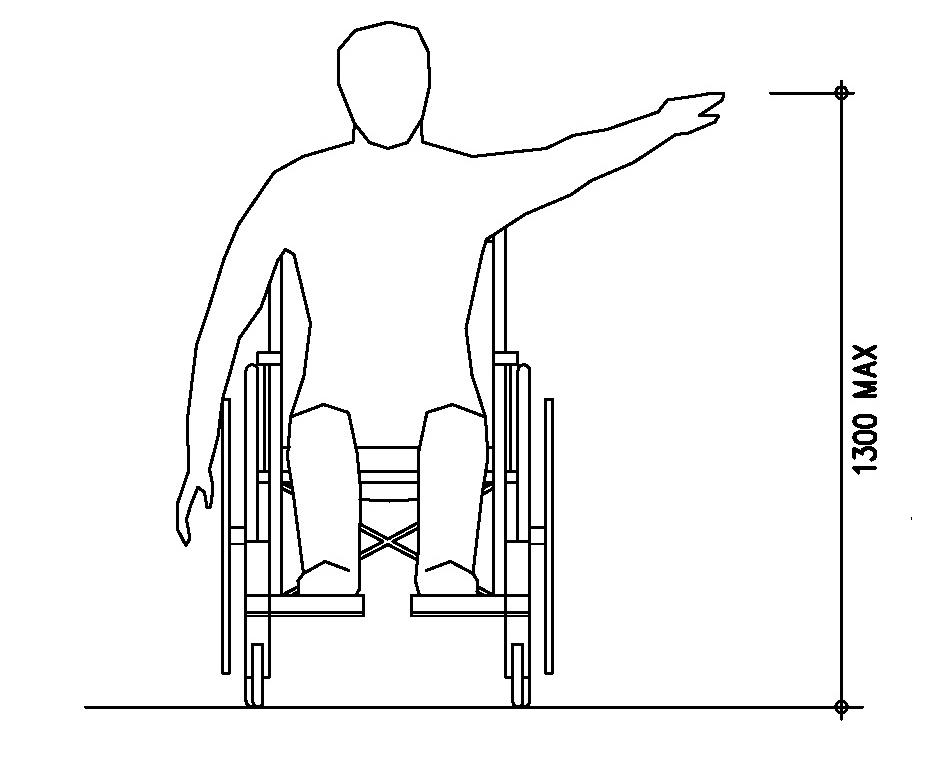
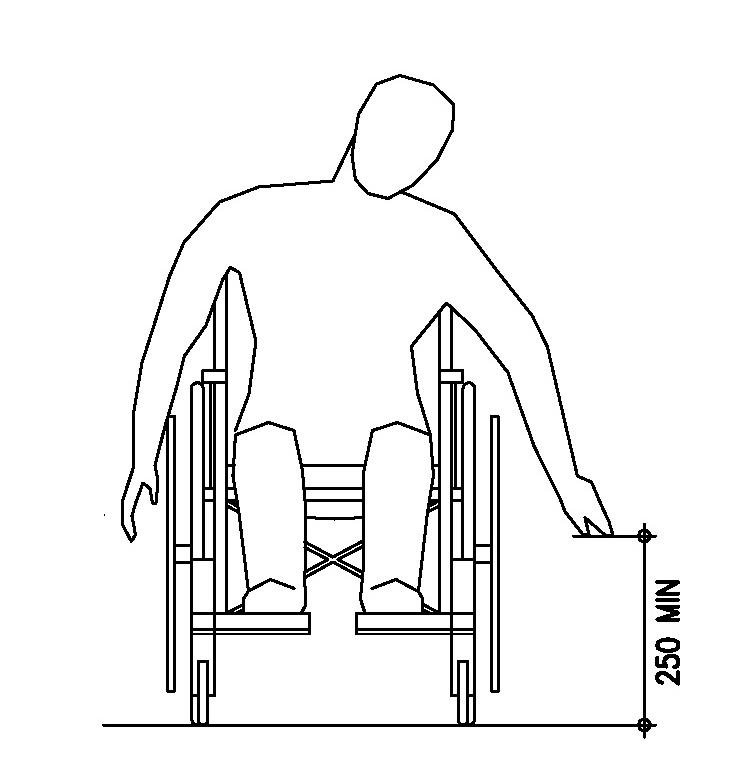
Figure A11
Persons using crutches
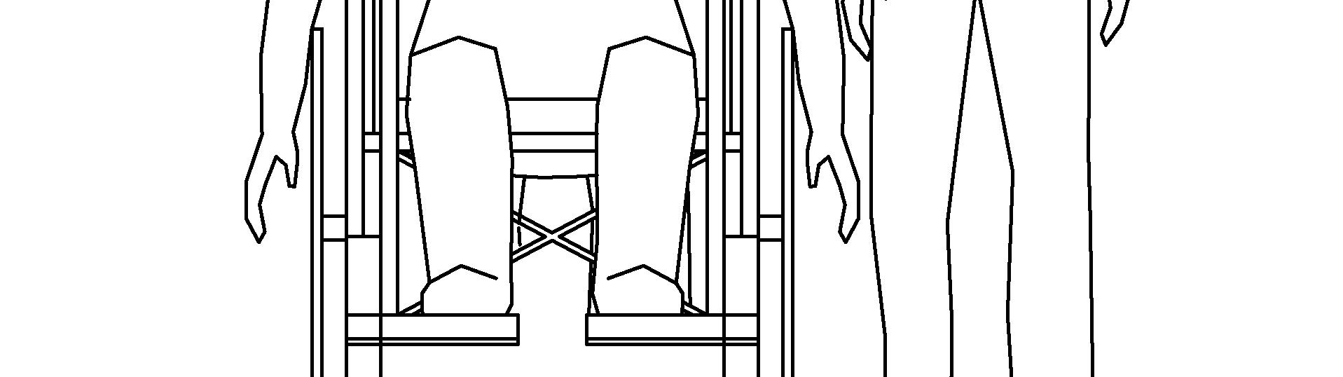

A/5
Persons with visual impairment using a long white cane

Detectable path dimension


Person with baby carriage

Path width for a person together with Path width for two wheelchair users a wheelchair user – Dimensions Required for General Pathway


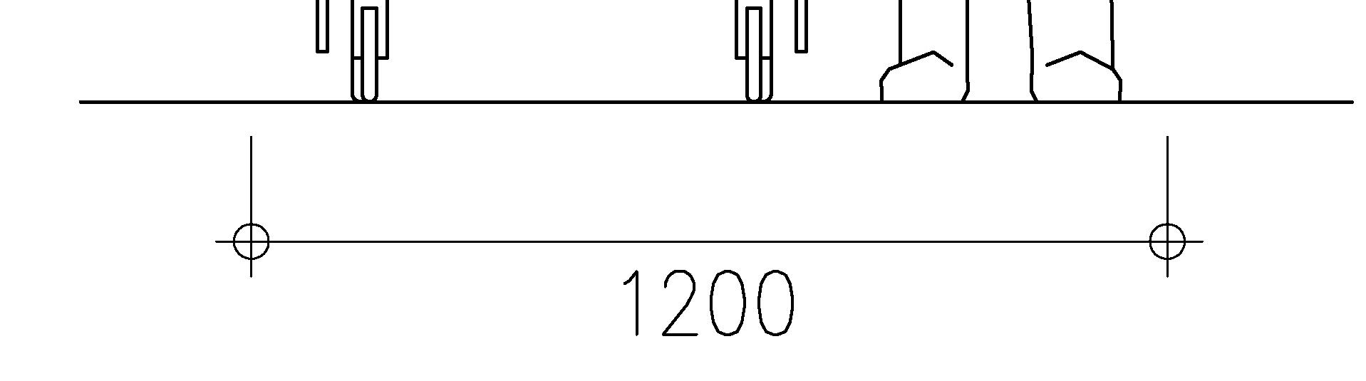
Appendix WheelchairGuidelinesBforTransfer and Movement
GUIDELINES FOR WHEELCHAIR TRANSFER AND MOVEMENT
Figure
B.1 Dimensions Of Wheelchairs
B/1 APPENDIX B
The dimensions of wheelchairs commonly used by persons with a disability in Hong Kong are provided at Figure B1. B1 - Dimensions of Wheelchair 10-27 36-100kgkg MIN
800
B/2
Figure B2 – Manoeuvring Spaces for Doorway
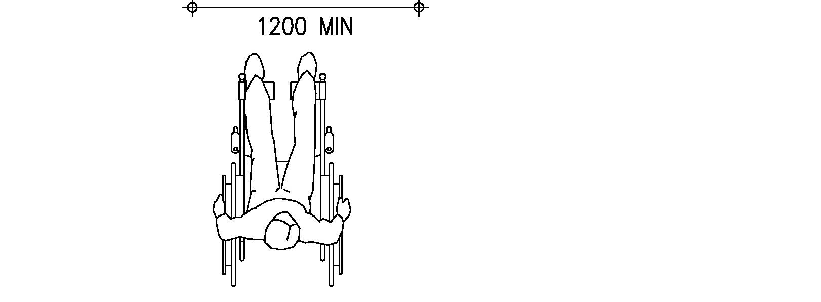
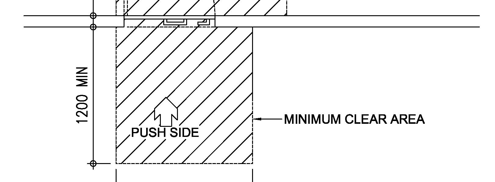
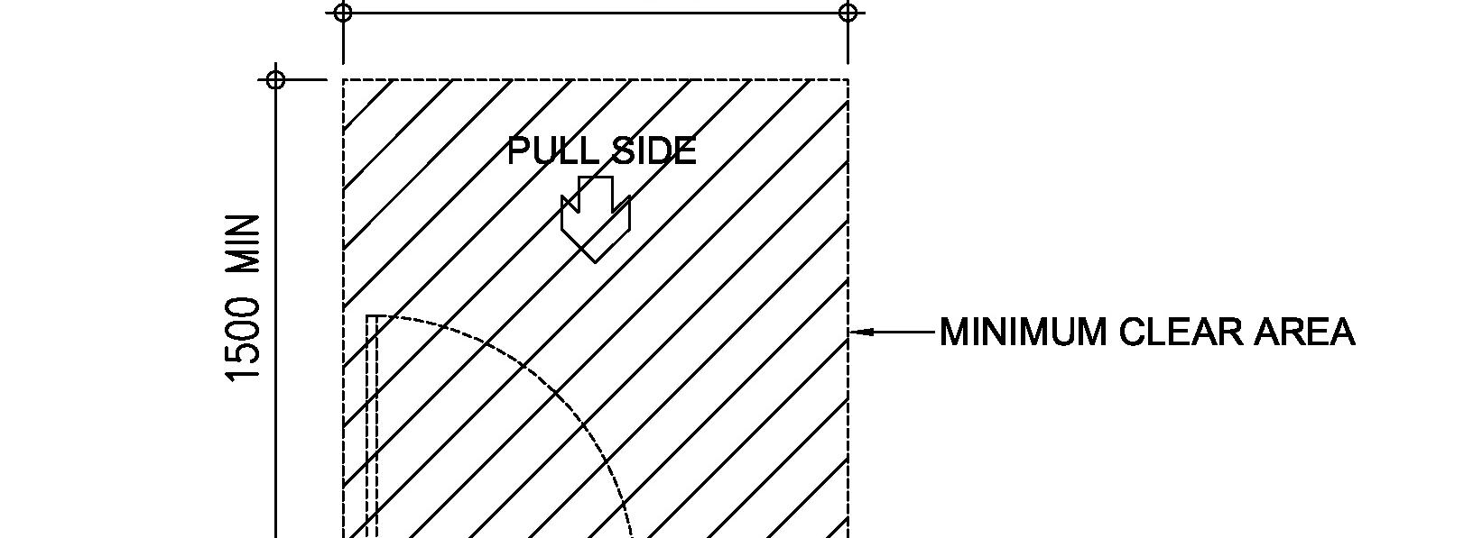
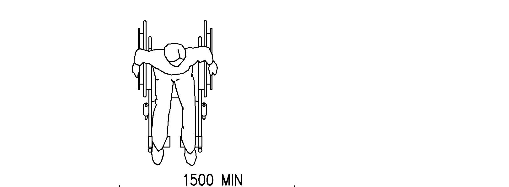

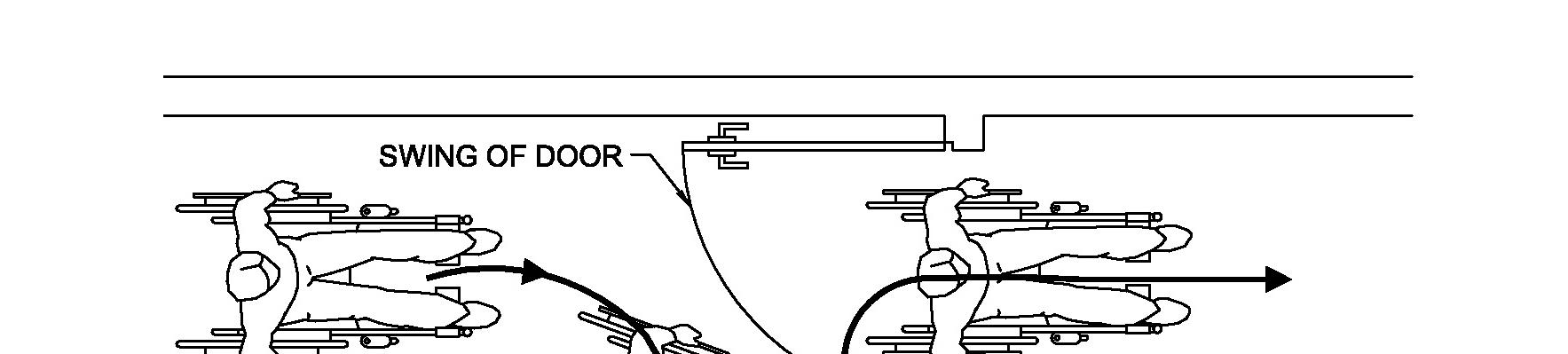
Figure B3 – Wheelchair Manoeuvring Space

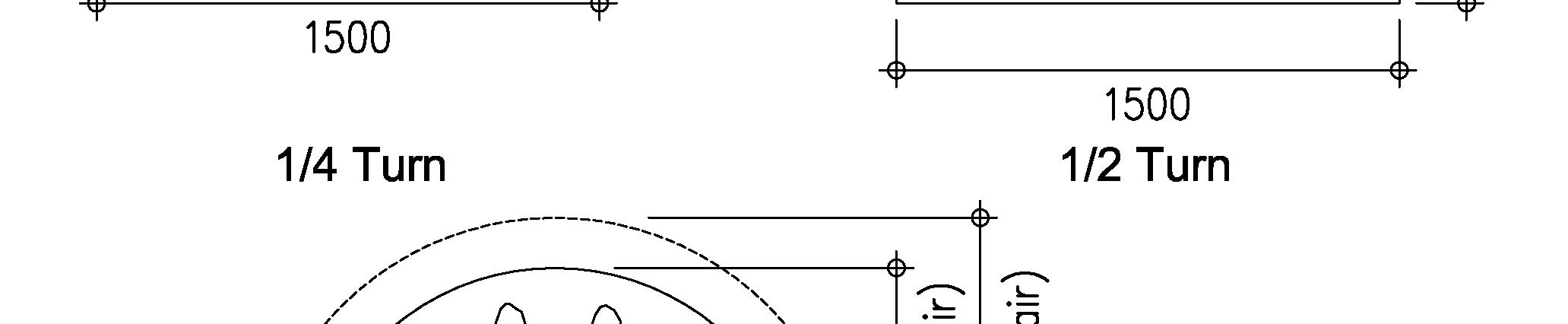
1/2
B/3
Complete Turn
WASTE
Figure B4 – Design Heights for Various Features
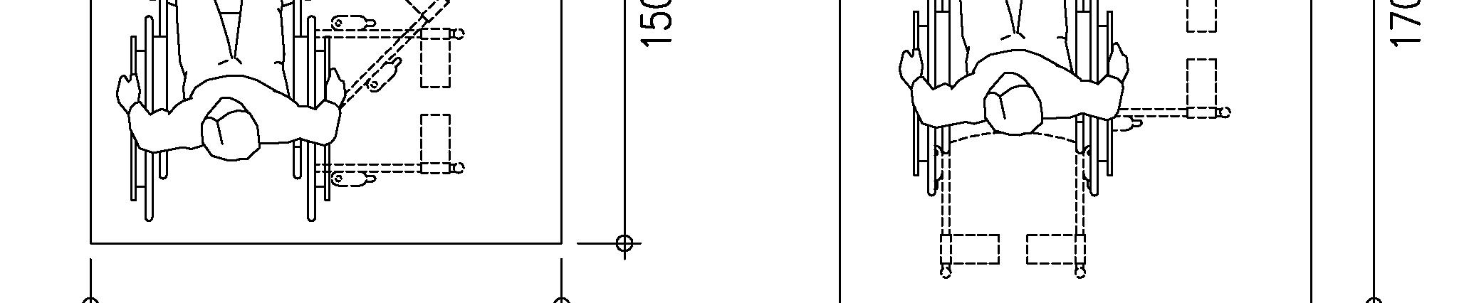
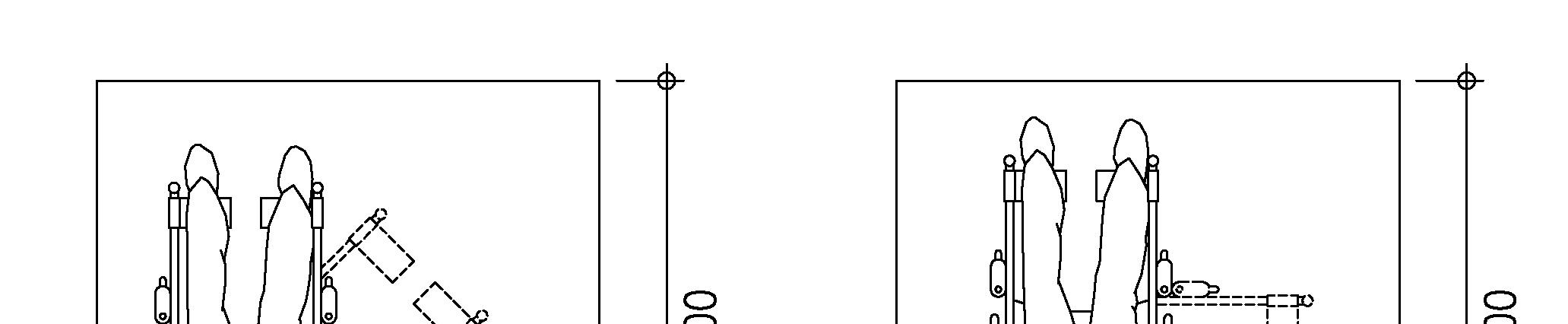
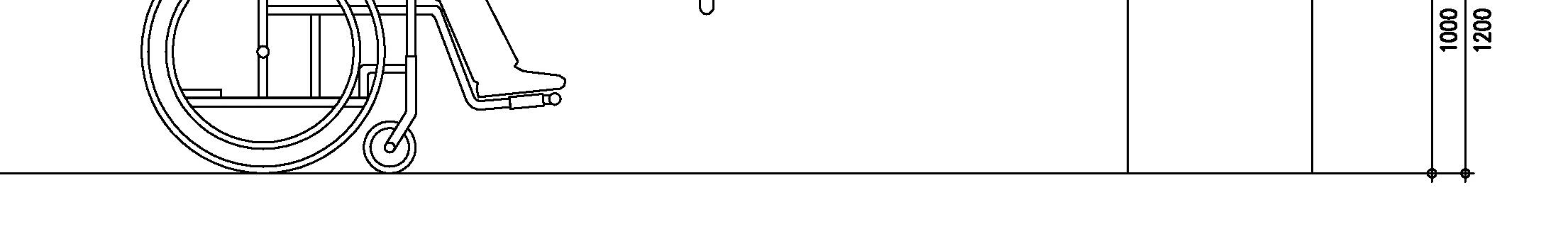
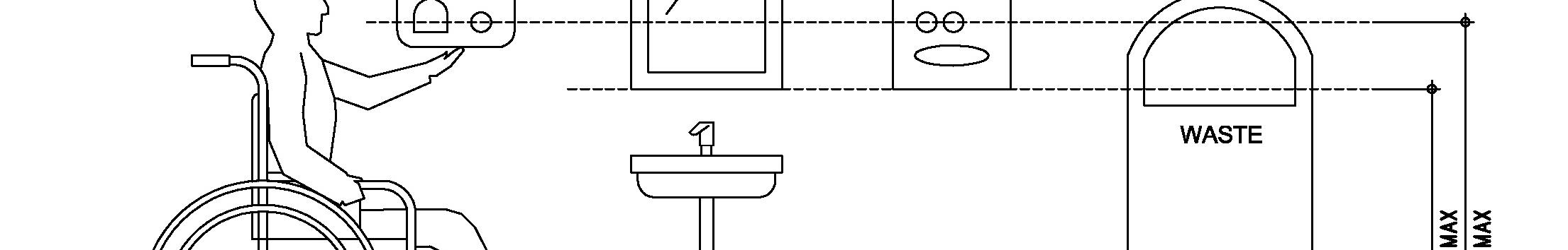

1/4 Turn Turn

Figure B5 – Diagonal Approach for Transferring from a wheelchair to a W.C. (Diagonal Approach)
B/4
Figure B7 – Frontal Approach for Transferring from a Wheelchair to a W.C.

Figure B6 – Side Approach for Transferring from a Wheelchair to a W.C.
B/5
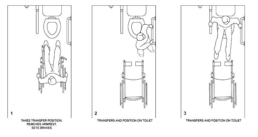
Appendix C
Slip Resistance of Flooring Materials
“Good” - Material surface satisfactory for normal use with an approximate “static coefficient of friction” value below 0.8 but at or above 0.5.
“Fair” - Material surface with moderate potential for slip, with an approximate “static coefficient of friction” value below 0.5 but at or above 0.2.
Excessive slip resistance can also be hazardous since it may create unexpected grip on the Gradingssurface.based
“Poor” - Unsafe material surface with high potential for slip, with an approximate “static coefficient of friction” value below 0.2.
C/1
SLIP RESISTANCE OF FLOORING MATERIALS
APPENDIX C
Commentary
“Slip resistance” is based on the frictional force required to keep a shoe heel or crutch tip from slipping on a walking surface. While the “dynamic coefficient of friction” during walking varies in a complex and non-uniform way, the “static coefficient of friction”, which can be measured in several ways, provides a close approximation of the slip resistance of a surface. However, it is generally recognized that the “static coefficient of friction” varies considerably due to the presence of contaminants, water, floor finishes, and other factors not under the control of the designer or builder and not subject to design and construction guidelines and that compliance of which would be difficult to measure on the building site. For details of method of measuring “slip resistance”, readers are suggested to make reference to some available overseas standards such as AS/NZS 4586-2004, AS/NZS 4663-2004, ASTM 1679, ASTM 1677, BS 7976-2, BS 8204 etc.
“Very Good” - Material surface suitable for use in areas where special design care is required, with an approximate “static coefficient of friction” value of 0.8 or above.
This appendix aims to provide design references of slip resistance for flooring materials and floor finishes.
on “static coefficient of friction” measured in “dry” condition are classified by:
Materials and finishes are graded under dry and wet conditions. The gradings given herein are for reference only, actual value of “static coefficient of friction” shall be subject to the manufacturer’s recommended characteristics.
Appendix D
Luminous Contrast
Types of contrast
D/1
Colour contrast is the difference between colours positioned on a colour wheel. For example violet is the contrast to yellow, red is contrasted to green. Colours can contrast on the basis of their lightness, saturation or hue. (a) lightness measures the relative amount of light reflected from a colour; (b) saturation relates to its intensity; and (c) hue refers to elementary colour names, that is red, green, blue etc. The perception of colour, however, can change with the type of light. Some people with visual impairment are unable to see colours as ageing and sight loss diminish their sensitivity of colour perception. Theref ore colour contrast on its own may not be sufficient to provide a visual contrast.
Luminous Contrast
Colour contrast
APPENDIX
D
Contrast refers to perceptible differences between different regions of an image or scene. There are two fundamental types of contrast: (a) Colour contrast, and (b) Luminous or brightness contrast.
Tint: color+white,resultinginalightervalue Tone: color+grey,resultinginadarkervalue Shade: color+black,deliveringthedarkestversionsofcolor
D/2
Luminous contrast is the amount of light reflected from one surface or component, compared to the amount of light reflected from the background or base surfaces. Luminous contrast is preferred to colour contrast because it offers light/dark differences that can be picked up more easily by people with visual impairment.
Luminous contrast
A 30% difference in luminous is generally the minimum discernible by a person with partial sight. Black and white have a 100% luminous contrast. Grey and black or grey and white have a 50% luminous contrast.
Two quite differently coloured surfaces may have a similar luminous. For example, cherry red on black has a high colour contrast but low luminous contrast and is not as visible as pale pink or yellow on black to people with visual impairment.
Contrast will only be of assistance to people with visual impairment if there is an appropriate quantity and quality of illumination with which to view the contrasting elements. At low light levels, the perception of contrast diminishes. Lighting levels should generally be relatively uniform and about 25% higher for people with low vision. Strong directional lighting casts shadows that can mask contrasting surfaces. Significant fluctuations in illumination level can reduce visibility due to the slower adaptive response of the eye in someone with low vision.
B1Where=light
Measurement of Luminous Contrast
D/3
The light reflectance value of a subject can be measured by means of a luminance meter with a 1 degree measurement field. Measurement will be taken from a viewing height of 1600mm + 100mm and with an angle between 40 to 50 degree to the vertical in direction of approach. “Luminous contrast” means the amount of light reflected from the surface of the object compared to the amount of light reflected from the surface of its surrounding background. Such contrast expressed in percent can be determined by: [(B1-B2) / B1] x 100
reflectance value (LRV) of the lighter area and B2 = light reflectance value (LRV) of the darker area.
Contrasting tactile warning strips to indicate the start and finish of a ramp; Contrasting doorframes, doors, skirting boards and architraves to assist with locating doors; Contrasting paving at doorways to assist with locating the entry; Contrastingandedges of steps, a roadway or poles in play areas to highlight potential hazards.
Lighting
Effective uses of luminous contrast include:
