TOPICAL ARTICLE
District heating and cooling energy network using CO2 as a heat and mass transfer fluid
Henchoz S, Favrat D, Girardin L, Marechal M - Switzerland
The 5th generation compact district heating and cooling networks in a temperature range of 10 to 16 °C have a great potential for energy savings by providing a heat source for decentralized heating heat pumps, a cold source for air-conditioning and a heat sink for refrigeration or cogeneration units. The energy balance of the network is achieved by a central plant equipped with a heating heat pump in winter operation and a heat dissipator in summer operation. They typically facilitate the synergy between users and allow the concept of a city without chimneys or cooling towers in the various buildings. One such concept is based on using the latent heat of the transfer fluid (CO2), with one saturated CO2 vapor pipe and one saturated CO2 liquid pipe. Studies show that up to 80 % of the final energy can be saved in urban areas, at a cost that is lower than the conventional technologies.
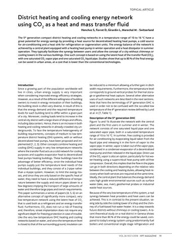
WINTER Free cooling user OFF
Heat pump user ON Central heat pump ON
Introduction Since a growing part of the population worldwide will live in cities, urban energy supply is very important when considering improved energy efficiency strategies. However, as a result of the different willingness of building owners to invest in energy renovation of their buildings, the building stock is often very diverse. A result of this is that the energy demand and the required temperature levels for each building tend to differ within a given part of a city. Moreover, cooling loads tend to increase in the central city district with a large share of shops and offices, including data centers. Hence, there is an increase in both heating and cooling networks in already crowded city undergrounds. To face the temperature heterogeneity of building requirements, concepts of medium to low temperature district heating (DH) systems, with or without decentralized heat pumps, have been proposed and implemented [1, 2, 3]. Other concepts combine heating and cooling (DHC) supply in very low temperature networks where the transfer fluid acts as a cold network for cooling purposes and supplies evaporator heat to decentralized heat pumps heating buildings. These buildings have the advantage of better efficiency, since the individual heat pumps supply just the temperature level needs of the individual buildings, and they consist of a 2-pipe rather than a 4-pipe system. However, to limit the exergy losses, and since they are only based on the specific heat of water, they need to have a reduced difference of temperature between the supply and return pipes (down to a few degrees) implying the transport of large amounts of water and therefore large pipes and trench requirements. This paper summarizes a series of papers [4, 5, 6] on an alternative concept of significantly more compact, very low temperature network using the latent heat of CO2 that is used both as a refrigerant and an energy transfer fluid. Furthermore, CO2 does not run a risk of freezing and, therefore, street implantation does not require any significant depth for freezing protection in case of trouble. Like the very low temperature DHC heating and cooling networks based on water, and since the temperature level is closed to that of the surrounding ground, insulation can
Download and share this article
be reduced to a minimum allowing a further gain in ditch width requirements. Furthermore, the temperature level corresponds to ground vertical probes for thermal storage or geothermal heat capture. Several other alternative uses of such networks are described in the next sections. Note that here the terminology of 5th generation DHC is used in order not to be confused with the so-called low temperature of the 4th generation review defined by Lund et al. in [7, Table 1]. Description of the 5th generation DHC Figure 1a and 1b illustrate the network with the central plant and the first users in summer and in winter. The network consists of one saturated liquid pipe and one saturated vapor pipe, both in a saturated temperature range of 10 to 16 °C. In summer, free cooling is provided for air conditioning by evaporating liquid taken from the liquid pipe and releasing it in the form of vapor to the vapor pipe. In winter, vapor is taken out of the vapor pipe, condensed in a condenser-evaporator of a decentralized heat pump and then released in the liquid pipe. Direct use of the CO2 vapor is also an option, particularly for hot water-heating using a supercritical heat pump with oil-free compressor. Overall, this implies that the flow in the pipes can go in both directions depending on the relative ratio between the cooling and heating duties, allowing heat recovery when both services are required at the same time. Ideally, the central plant that balances the energy demand uses high grade environmental sources such as surface water (lake, sea, river), geothermal probes or industrial waste heat sources. Because of the very low temperature of this system, a real synergy between heat providers and heat users can be achieved. This is in contrast to the present situation, seeing side by side the cooling tower of a shop and the chimney of a fuel-based hot water heater. It is a step towards future districts without chimneys or cooling towers. A recent theoretical study on a real district in Geneva shows that more than 80 % of the energy could be saved, compared to today’s energy system using predominantly fuel boilers and conventional single stage refrigeration and
VOL.36 NO 1/2018 HPT MAGAZINE
19