


WARNING
Do not use means to accelerate the defrosting process or to clean, other than those recommended by the manufacturer. The appliance shall be stored in a room without continuously operating ignition sources (for example: open flames, an operating gas appliance or an operating electric heater)
Do not pierce or burn.
Be aware that refrigerants may not contain an odour.
Initial safety checks shall include:
① That capacitors are discharged: this shall be done in a safe manner to avoid possibility of sparking;
② That no live electrical components and wiring are exposed while charging, recovering or purging the system;
③ That there is continuity of earth bonding.
Checks to the area
Prior to beginning work on systems containing flammable refrigerants, safety checks are necessary to ensure that the risk of ignition is minimized. For repair to the refrigerating system, the following precautions shall be completed prior to conducting work on the system.
Work procedure
Work shall be undertaken under a controlled procedure so as to minimize the risk of a flammable gas or vapour being present while the work is being performed.
General work area
All maintenance staff and others working in the local area shall be instructed on the nature of work being carried out. Work in confined spaces shall be avoided.
The area shall be checked with an appropriate refrigerant detector prior to and during work, to ensure the technician is aware of potentially flammable atmospheres. Ensure that the leak detection equipment being used is suitable for use with flammable refrigerants, i.e. non-sparking, adequately sealed or intrinsically safe.
If any hot work is to be conducted on the refrigerating equipment or any associated parts, appropriate fire extinguishing equipment shall be available to hand. Have a dry powder or CO2 fire extinguisher adjacent to the charging area.
No person carrying out work in relation to a refrigeration system which involves exposing any pipe work that contains or has contained flammable refrigerant shall use any sources of ignition in such a manner that it may lead to the risk of fire or explosion. All possible ignition sources, including cigarette smoking, should be kept sufficiently far away from the site of installation, repairing, removing and disposal, during which flammable refrigerant can possibly be released to the surrounding space. Prior to work taking place, the area around the equipment is to be surveyed to make sure that there are no flammable hazards or ignition risks. "No Smoking"signs shall be displayed.
Ensure that the area is in the open or that it is adequately ventilated before breaking into the system or conducting any hot work. A degree of ventilation shall continue during the period that the work is carried out. The ventilation should safely disperse any released refrigerant and preferably expel it externally into the atmosphere.
Where electrical components are being changed, they shall be fit for the purpose and to the correct specification.At all times the manufacturer’s maintenance and service guidelines shall be followed. If in doubt consult the manufacturer’s technical department for assistance. The following checks shall be applied to installations using flammable refrigerants:
① The charge size is in accordance with the room size within which the refrigerant containing parts are installed;
② The ventilation machinery and outlets are operating adequately and are not obstructed;
③ If an indirect refrigerating circuit is being used, the secondary circuit shall be checked for the presence of refrigerant;
④ Marking to the equipment continues to be visible and legible. Markings and signs that are illegible shall be corrected;
⑤ Refrigeration pipe or components are installed in a position where they are unlikely to be exposed to any substance which may corrode refrigerant containing components, unless the components are constructed of materials which are inherently resistant to being corroded or are suitably protected against being so corroded.
DD.5.1 During repairs to sealed components, all electrical supplies shall be disconnected from the equipment being worked upon prior to any removal of sealed covers, etc. If it is absolutely necessary to have an electrical supply to equipment during servicing, then a permanently operating form of leak detection shall be located at the most critical point to warn of a potentially hazardous situation.
DD.5.2 Particular attention shall be paid to the following to ensure that by working on electrical components, the casing is not altered in such a way that the level of protection is affected. This shall include damage to cables, excessive number of connections, terminals not made to original specification, damage to seals, incorrect fitting of glands, etc.
Ensure that the apparatus is mounted securely.
Ensure that seals or sealing materials have not degraded to the point that they no longer serve the purpose of preventing the ingress of flammable atmospheres. Replacement parts shall be in accordance with the manufacturer’s specifications.
Do not apply any permanent inductive or capacitance loads to the circuit without ensuring that this will not exceed the permissible voltage and current permitted for the equipment in use.
Intrinsically safe components are the only types that can be worked on while live in the presence of a flammable atmosphere. The test apparatus shall be at the correct rating.
Replace components only with parts specified by the manufacturer. Other parts may result in the ignition of refrigerant in the atmosphere from a leak.
NOTE:The use of silicon sealant can inhibit the effectiveness of some types of leak detection equipment.
Intrinsically safe components do not have to be isolated prior to working on them.
Check that cabling will not be subject to wear, corrosion, excessive pressure, vibration, sharp edges or any other adverse environmental effects. The check shall also take into account the effects of aging or continual vibration from sources such as compressors or fans.
Under no circumstances shall potential sources of ignition be used in the searching for or detection of refrigerant leaks. A halide torch (or any other detector using a naked flame) shall not be used.
The following leak detection methods are deemed acceptable for systems containing flammable refrigerants.
Electronic leak detectors shall be used to detect flammable refrigerants, but the sensitivity may not be adequate, or may need re-calibration. (Detection equipment shall be calibrated in a refrigerant-free area.) Ensure that the detector is not a potential source of ignition and is suitable for the refrigerant used. Leak detection equipment shall be set at a percentage of the LFL of the refrigerant and shall be calibrated to the refrigerant employed and the appropriate percentage of gas (25 % maximum) is confirmed.
Leak detection fluids are suitable for use with most refrigerants but the use of detergents containing chlorine shall be avoided as the chlorine may react with the refrigerant and corrode the copper pipe-work.
If a leak is suspected, all naked flames shall be removed/extinguished. If a leakage of refrigerant is found which requires brazing, all of the refrigerant shall be recovered from the system, or isolated (by means of shut off valves) in a part of the system remote from the leak. Oxygen free nitrogen (OFN) shall then be purged through the system both before and during the brazing process.
When breaking into the refrigerant circuit to make repairs – or for any other purpose –conventional procedures shall be used. However, it is important that best practice is followed since flammability is a consideration. The following procedure shall be adhered to:
① Remove refrigerant;
② Purge the circuit with inert gas;
③ Evacuate;
④ Purge again with inert gas;
⑤ Open the circuit by cutting or brazing.
The refrigerant charge shall be recovered into the correct recovery cylinders. The system shall be "flushed"with OFN to render the unit safe. This process may need to be repeated several times. Compressed air or oxygen shall not be used for this task.
Flushing shall be achieved by breaking the vacuum in the system with OFN and continuing to fill until the working pressure is achieved, then venting to atmosphere, and finally pulling down to a vacuum. This process shall be repeated until no refrigerant is within the system. When the final OFN charge is used, the system shall be vented down to atmospheric pressure to enable work to take place. This operation is absolutely vital if brazing operations on the pipework are to take place.
Ensure that the outlet for the vacuum pump is not close to any ignition sources and there is ventilation available.
In addition to conventional charging procedures, the following requirements shall be followed:
① Ensure that contamination of different refrigerants does not occur when using charging equipment. Hoses or lines shall be as short as possible to minimize the amount of refrigerant contained in them. Cylinders shall be kept upright.
② Ensure that the refrigeration system is earthed prior to charging the system with refrigerant.
③ Label the system when charging is complete (if not already).
④ Extreme care shall be taken not to overfill the refrigeration system. Prior to recharging the system it shall be pressure tested with OFN. The system shall be leak tested on completion of charging but prior to commissioning. A follow up leak test shall be carried out prior to leaving the site.
Before carrying out this procedure, it is essential that the technician is completely familiar with the equipment and all its detail. It is recommended good practice that all refrigerants are recovered safely. Prior to the task being carried out, an oil and refrigerant sample shall be taken in case analysis is required prior to re-use of reclaimed refrigerant. It is essential that electrical power is available before the task is commenced.
① Become familiar with the equipment and its operation.
② Isolate system electrically.
③ Before attempting the procedure ensure that:
⚫ Mechanical handling equipment is available, if required, for handling refrigerant cylinders;
⚫ All personal protective equipment is available and being used correctly;
⚫ The recovery process is supervised at all times by a competent person;
⚫ Recovery equipment and cylinders conform to the appropriate standards.
④ Pump down refrigerant system, if possible.
⑤ If a vacuum is not possible, make a manifold so that refrigerant can be removed from various parts of the system.
⑥ Make sure that cylinder is situated on the scales before recovery takes place.
⑦ Start the recovery machine and operate in accordance with manufacturer's instructions.
⑧ Do not overfill cylinders. (No more than 80 % volume liquid charge).
⑨ Do not exceed the maximum working pressure of the cylinder, even temporarily.
⑩ When the cylinders have been filled correctly and the process completed, make sure that the cylinders and the equipment are removed from site promptly and all isolation valves on the equipment are closed off.
11 Recovered refrigerant shall not be charged into another refrigeration system unless it has been cleaned and checked.
Equipment shall be labeled stating that it has been decommissioned and emptied of refrigerant. The label shall be dated and signed. Ensure that there are labels on the equipment stating the equipment contains flammable refrigerant.
When removing refrigerant from a system, either for servicing or decommissioning, it is recommended good practice that all refrigerants are removed safely. When transferring refrigerant into cylinders, ensure that only appropriate refrigerant recovery cylinders are employed. Ensure that the correct number of cylinders for holding the total system charge are available. All cylinders to be used are designated for the recovered refrigerant and labeled for that refrigerant (i.e. special cylinders for the recovery of refrigerant). Cylinders shall be complete with pressure relief valve and associated shut-off valves in good working order. Empty recovery cylinders are evacuated and, if possible, cooled before recovery occurs.
The recovery equipment shall be in good working order with a set of instructions concerning the equipment that is at hand and shall be suitable for the recovery of flammable refrigerants. In addition, a set of calibrated weighing scales shall be available and in good working order. Hoses shall be complete with leak-free disconnect couplings and in good condition. Before using the recovery machine, check that it is in satisfactory working order, has been properly maintained and that any associated electrical components are sealed to prevent ignition in the event of a refrigerant release. Consult manufacturer if in doubt.
The recovered refrigerant shall be returned to the refrigerant supplier in the correct recovery cylinder, and the relevant Waste Transfer Note arranged. Do not mix refrigerants in recovery units and especially not in cylinders.
If compressors or compressor oils are to be removed, ensure that they have been evacuated to an acceptable level to make certain that flammable refrigerant does not remain within the lubricant. The evacuation process shall be carried out prior to returning the compressor to the suppliers. Only electric heating to the compressor body shall be employed to accelerate this process. When oil is drained from a system, it shall be carried out safely.
The precautions listed here are divided into the following types. They are quite important, so be sure to follow them carefully.Meanings of DANGER, WARNING, CAUTION and NOTE symbols.

WARNING
The symbol shows that this appliance uses a flammable refrigerant. If the refrigerant is leaked and exposed to an external ignition source, there is a risk of fire.
WARNING All information marked with this symbol is important and should be viewed carefully.
WARNING

CAUTION

CAUTION
This symbol shows that there might be an electric shock if the appliance still connects the power cleaning, examination and repair.
This symbol shows Anti-freezing protection. It is necessary to prevent the freezing of heat exchanger or water pipes, the power of unit can not be shut off in the ambient temperature lower than 2℃. All the water in the unit and plumbing system must be drained out if the unit will be turned off for a long time.
This symbol shows that the operation manual should be read carefully.
CAUTION
This symbol shows that when you intend to discard this chiller, it must be sent to an appropriate facility for recovery and recycling
To keep users under safe working condition and property safety, please follow the instructions below:
① Wrong operation may result in injury or damage;
② Please install the unit in compliance with local laws, regulations and standards;
③ Confirm power voltage and frequency;
④ The unit is only used with grounding sockets;
⑤ Independent switch must be offered with the unit.
The following safety factors need to be considered:
① Please read the following warnings before installation;
② Be sure to check the details that need attention, including safety factors;
③ After reading the installation instructions, be sure to save them for future reference.
Warning
Make sure that the unit is installed safely and reliably.
⚫ If the unit is not secure or not installed, it may cause damage. The minimum support weight required for installation is 21g/㎜²
⚫ If the unit was installed in a closed area or limited space, please consider the size of room and ventilation to prevent suffocation caused by refrigerant leakage.
① Use a specific wire and fasten it to terminal block so that the connection will prevent pressure from being applied to parts.
② Wrong wiring will cause fire.
Please connect power wire accurately according to wiring diagram on the manual to avoid burnout of the unit or fire.
③ Be sure to use correct material during installing.
Wrong parts or wrong materials may result in fire, electric shock, or falling of the unit.
④ Install on the ground safely, please read installation instructions. Improper installation may result in fire, electric shock, falling of the unit, or water leaking.
⑤ Use professional tools for doing electrical work. If power supply capacity is insufficient or circuit is not completed, it may cause fire or electric shock.
⑥ The unit must have grounding device. If power supply does not have grounding device, be sure not to connect the unit.
⑦ The unit should be only removed and repaired by professional technician. Improper movement or maintenance of the unit may cause water leakage, electric shock, or fire. Please find a professional technician to do
⑧ Don't unplug or plug power during operation.It may cause fire or electric shock.
⑨ Don't touch or operate the unit when your hands are wet. It may cause fire or electric shock.
⑩ Don't place heaters or other electrical appliances near the power wire.It may cause fire or electric shock.
11 The water must not be poured directly from the unit. Do not let water to permeate into the electrical components.
① Do not install the unit in a location where there may be flammable gas.
② If there is flammable gas around the unit, it will cause explosion.
According to the instruction to carry out drainage system and pipeline work. If drainage system or pipeline is defective, water leakage will occur. And it should be disposed immediately to prevent other household products from getting wet and damage.
③ Do not clean the unit while power is on. Turn off power before cleaning the unit. If not it may result in injury from a high-speed fan or electric shock.
④ Stop operating the unit once there is a problem or an fault code
Please turn off power and stop running the unit. Otherwise it may cause electric shock or fire.
⑤ Be careful when the unit is not packed or not installed. Pay attention to sharp edges and fins of heat exchanger.
⑥ After installation or repair, please confirm refrigerant is not leaking. If refrigerant is not enough, the unit will not work properly.
⑦ The installation of external unit must be flat and firm.
Avoid abnormal vibration and noise.
⑧ Don’t put your fingers into fan and evaporator. High speed running fan will result in serious injury.
⑨ This device is not designed for people who is physically or mentally weak (including children) and who does not have experience and knowledge of heating and cooling system. Unless it is used under direction and supervision of professional technician, or has received training on the using of this unit. Children must use it under supervision of an adult to ensure that they use the unit safely. If power wire is damaged, it must be replaced by a professional technician to avoid danger.
After unpacking, please check if you have all the following components.


2.2. Dimensions of the Unit

2.3. Main Parts of the Unit


Revitalice Arctic Chiller Type Heating/Cooling
Water Volume&Chilling Time (From 25℃to 5℃)
Ambient Temp. (30℃)
50L: ≤1.3h
100L: ≤2.5h
200L: ≤5h
300L: ≤7.5h
500L: ≤12.5h
Heating Water Temp. Range (℃) 15-40
Cooling Water Temp. Range (℃) 2-28
Heating operating Ambient Temp.
Range (℃) 5-43
Cooling operating Ambient Temp.
Range (℃) 10-43
[Cooling] Ambient: 35℃, Water Outlet:
27℃,Water Flow:0.7m³/h
Cooling Capacity (W) 1600
Input (W)
(A)
[Cooling] Ambient: 27℃, Water Outlet:
5℃,Water Flow:0.7m³/h
[Cooling] Ambient 15℃, Water Outlet:
5℃,Water Flow:0.7m³/h
Cooling Capacity (W) 1556
Input (W)
(A)
[Heating] Ambient: 27℃, Water Inlet:
26℃, Humidity: 80%,Water Flow: 0.7m³/h
[Heating] Ambient: 15℃, Water Inlet:
26℃, Humidity: 70%,Water Flow:
0.7m³/h
Heating Capacity (W) 2320
[Heating] Ambient: 27℃, Water Inlet:
38℃, Humidity: 80%,Water Flow:
0.7m³/h
Heating Capacity (W)
Power Input (W)
(A)
Pump Input Power (W)
Power
(W)
Refrigerant R32
Sound Pressure Level at 1m [dB(A)] 49
Sound Pressure Level at 10m [dB(A)] 34
Compressor Brand GMCC
Compressor Type Rotary
Water Pipe Connection (mm) φ20
Water Heat Exchanger Titanium
Circulation Pump Built-in Water Pump With Self-priming System
Sterilizer Function Built-in UV Sterilizer Built-in Ozone Generator
Water Filter Built-in
Transport wheels Yes Carry Handle Yes
Easy Maintenance Plate Yes
Quick Connectors Yes
Water Proof Level IPX4
Display LED Screen
Net Dimensions [(L×W×H) mm] 489×437×500
Net Weight (kg) 37
The above data are for reference only, the specific data are subject to actual product.
2.5. Operation Figure of The Unit
Cooling mode
Heating mode

The ice bath chiller should be operated within the range of appropriate ambient temperature and water temperature as above diagram. If the operation range is exceeded, it may cause the ice bath chiller damaged or shortened its service life.
WARNING: The heat pump must be installed by a professional team. The users are not qualified to install by themselves, otherwise the heat pump might be damaged and risky for users’ safety.
This section is provided for information purposes only and must be checked and adapted if necessary according to the actual installation conditions.
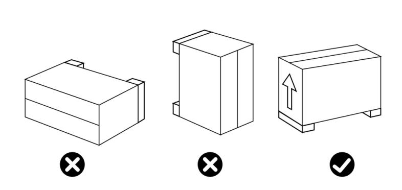
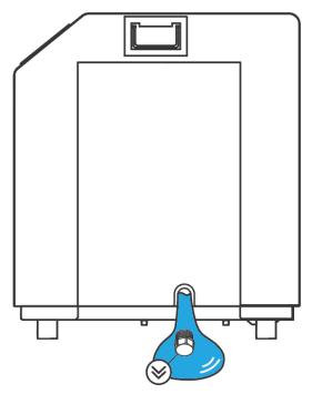
1. When storing or moving the bath chiller, the bath chiller should be at the upright position.
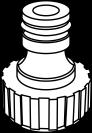
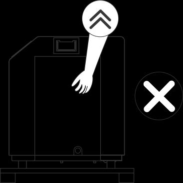
2.When moving the bath chiller, do not lift the water union since the titanium heat exchanger inside the bath chiller will be damaged.
3.2.1
Please comply with the following rules concerning the choice of bath chiller location.
① The unit’s future location must be easily accessible for convenient operation and maintenance.
② It must be installed on the ground, fixed ideally on a level concrete floor. Ensure that the floor is sufficiently stable and can support the weight of the unit.
③ Awater drainage device must be provided close to the unit in order to protect the area where it is installed.
④ If necessary, the unit may be raised by using suitable mounting pads designed to support its weight.
⑤ Check that the unit is properly ventilated, that the air outlet is not facing the windows of
neighbouring buildings and that the exhaust air cannot return. In addition, provide sufficient space around the unit for servicing and maintenance operations.
⑥ The unit must not be installed in an area exposedto oil, flammable gases, corrosive products, sulphur compounds or close to high frequency equipment.
⑦ To prevent mud splashes, do not install the unit near a road or track.
⑧ To avoid causing nuisance to neighbors, make sure the unit is installed so that it is positioned towards the area that is least sensitive to noise.
⑨ Keep the unit as much as possible out of the reach of children
⑩ Installation space: (Unit: mm)
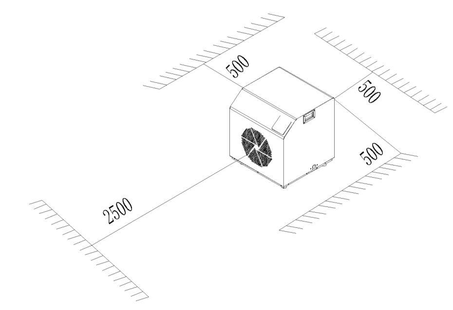
Do not put anything less than one meter in front of the bath chiller.
Leave 500 mm of empty space on the sides and back of the bath chiller and free ventilation above Keep the whole installation ventilation and do not leave any obstacles above or in front of the device!
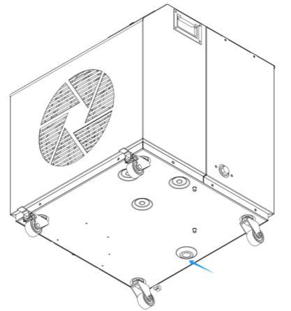
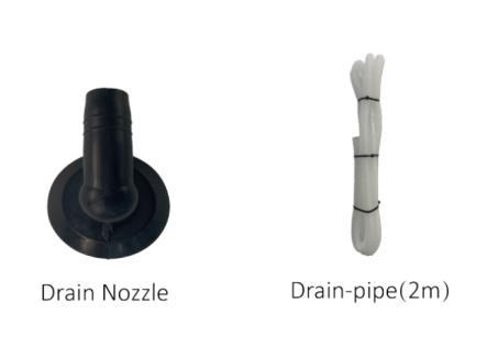
For indoor use, it is necessary to drain the condensate water from the heat pump into the drain, for example, a floor drain or atank. It is the customer's responsibility to arrange this
When the chiller is running, there will be condensation water discharged from the bottom, please attach the drain pipe in to the drain nozzle and after the drainage nozzle should be attach into the hole and clip it well.
Note:The drain pipe should be tilted downward to drain the condensed water better
3.2.2
NOTE:
⚫ The filter must be cleaned regularly to ensure that water in the system is clean and avoid blocking of filter.
⚫ If the unit is not running during winter months, please disconnect power supply and let out drain water from unit through drainage valve. If ambient temp. of running unit is below 0℃, please keep water pump running.
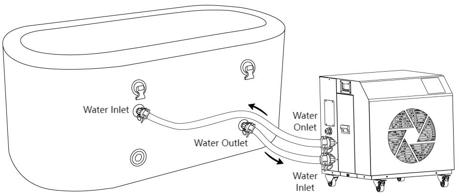
⚫ The installation diagram is shown in the following figures:
3.2.3
To function safely and maintain the integrity of your electrical system, the unit must be connected to a general electricity supply in accordance with the following regulations:
① Upstream, the general electricity supply must be protected by a 30mA differential switch.
② The bath chiller must be connected to a suitable D-curve circuit breaker in accordance with current standards and regulations in the country where the system is installed.
③ The electricity supply cable must be adapted to match the unit’s rated power and the length of wiring required by the installation. The cable must be suitable for outdoor use.
④ For a three-phase system, it is essential to connect the phases in the correct sequence.If the phases are inverted, the bath chiller’s compressor will not work.
⑤ In places open to the public, it is mandatory to install an emergency stop button close to the bath chiller.
3.2.4 Electrical Connection
WARNING: Power supply of ice bath chiller must be disconnected before any operation. Please comply with the following instructions to connect the ice bath chiller.
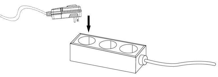
Step 1: Prepare a socket

Step 2: Insert the plug into the socket as the following picture shows Ensure that all electrical equipment is properly grounded. Plug Power Supply
3.2.5 Wiring Diagram
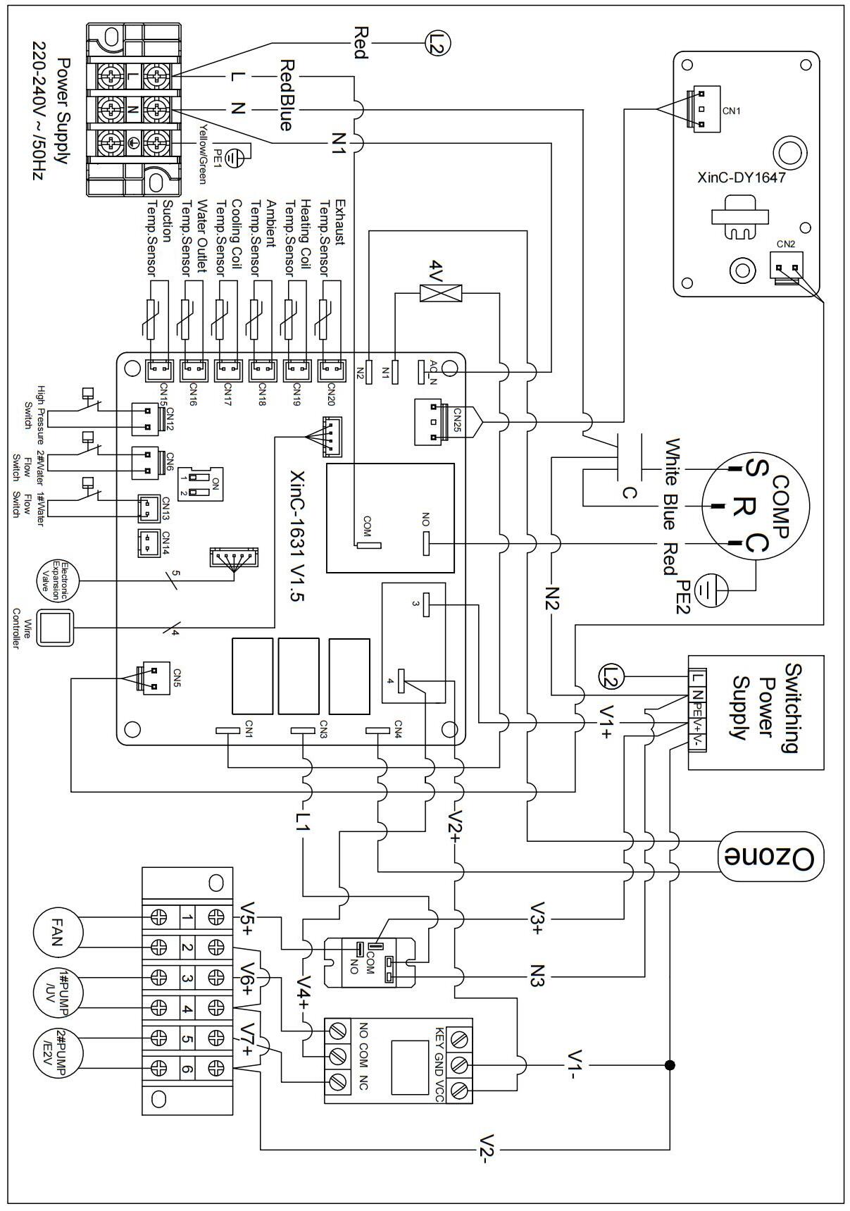
WARNING:Power supply of bath chiller must be disconnected before any operation.
Please comply with the following instruction to connect bath chiller
Step 1: Prepare a socket
Step 2: Insert plug into socket as the following picture shows
3.3.
3.3.1
WARNING:Please check all the wiring carefully before turning on the bath chiller
Before running test, confirm below items and write √ in block;
Correct unit installation
Power supply voltage is the same as unit rated voltage
Correct piping and wiring
Air inlet & outlet port of unit is unblocked
Drainage and venting is unblocked and no water leaking
Leakage protector is working
Piping insulation is working
Ground wire is connected correctly
Connect the drain nozzle and drain pipe
3.3.2 Trial Running
Step 1:Running test can begin after completing all installation;
Step 2:All wiring and piping should be connected well and carefully checked, then fill water tank with water before power is switched on;
Step 3:Emptying all air within pipes and water tank, press "on-off"button on control panel to run the unit at setting temp.;
Step 4:Items need to be checked during running test:
① During the first running, unit current is normal or not;
② Each function button on control panel is normal or not;
③ Display screen is normal or not;
④ Are there any leakage in the whole heating circulation system;
⑤ Condensate drain is normal or not;
⑥ Are there any abnormal sound or vibration during running?
3.4.
3.4.1.
There is some grease in the titanium heat exchanger of the ice bath chiller, the grease will flow into the ice bath pool with the water during the ice bath. So please clean the ice bath chiller before enjoying the ice bath for the first time.
Please clean the ice bath chiller as below steps:
Tool: Dishwashing liquid (Or other detergent that do not harm the human body)
① Connect the ice bathtub and ice bath chiller.
② Add water into the ice bathtub until it is about 5cm above the ice bathtub outlet.
③ Add detergent to the bathtub
④ Turn on the ice bath chiller, set the heating mode and adjust the target temperature to 40℃
⑤ Keep the ice bath chiller operating for 30 minutes to 1 hour, then turn off the ice bath chiller and drain the water in the ice bathtub
⑥ Add water into the ice bathtub until it is about 5cm above the ice bathtub outlet.
⑦ Restart the ice bath chiller, set the heating mode and adjust the target temperature to 40℃
⑧ Keep the ice bath chiller operation for 30 minutes to clean the water system inside the ice bath chiller. Then turn off the ice bath chiller and drain the water in the ice bathtub
3.4.2.
⚫ An adult will produce 1~2 oz of sebum every day, the sebums will secreted by the user's body and will enter the ice bath machine slowly during the ice bath. The chiller cooling affection will get poor due to sebum blockage, it is recommended to clean the ice bath chiller every 2~3 months if you enjoy the ice bath frequently.
⚫ If the machine is not used for a long time, it is also necessary to clean the machine before restarting it to get a clean ice bath
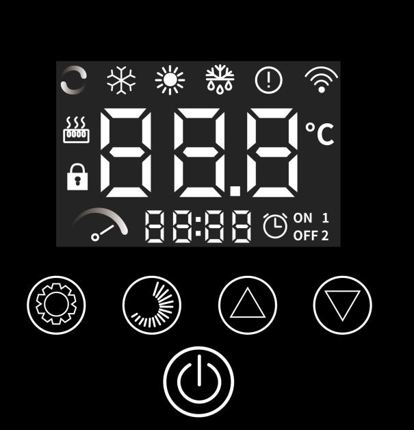


Under the main interface, press to turn on/off. OFF will be showed in the display if you turn off the unit.
⚫ If the unit has no input operation for 60 seconds, the wire controller display screen will enter the dormant state, and the screen will automatically lock, and the icon of the screen is light.
⚫ In the state of locking machine, after pressing the for 3 seconds, the buzzer start "beep", remove the lock button and the icon turns off.


⚫ Under the main interface, long press for 3 seconds to enter the query interface, query the user parameters by pressing or ⚫ In the user parameter query interface, select a parameter, press to set the current user parameters The parameter will become a flashing state,press or to modify the current user parameter value, and then press to confirm the change of parameter value, and return the parameter query status. (PS: Parameters do not flash in query state; parameters flash in setting state)
⚫ In the user parameter query or user parameter setting interface, if there is non-operation for 30 seconds, the changed parameter value will be automatically saved, exit the user parameter query interface or user parameter setting interface.Press also can exit
5 Sterilizer function
This function is only available for the chillers equipped with sterilizer.
Parameter 9(0 Manual /1 Auto,default is 0)
⚫ When the value of parameter 9 is 0, press for 3 seconds to start sterilizer function, icon will occur. Press for 3 seconds again to stop sterilizer function, icon will disappear.
⚫ When the value of parameter 9 is 1, if the unit is on, the sterilizer function will start for 20 minutes and then stop for 20 minutes, and will cycle as this logic.
⚫ In the main interface, press for 5 seconds to enter the realtime clock setting interface, the hours and minutes of the clock will flash together.

⚫ In the real-time clock setting interface, press the , the hour part will flash, and the minute part will stop flashing. At this time, press or to set the hour of the real-time clock.
6 Real -time clock setting

⚫ After setting the hour part, press again, the numbers in the minute part will flash and the hour part will stop flashing. At this time, press or to set the minutes of the real-time clock.
⚫ After the minute part is set, press again to confirm the realtime clock setting and return to the main interface.

⚫ In the real-time clock setting interface, press to confirm the current real-time clock setting value and return to the main interface.
⚫ In the real-time clock setting interface, if there is no key operation for 30 seconds, the current real-time clock setting value will be confirmed and return to the main interface.
⚫ Under the main interface, press the to enter the setting interface of entering the timer group
⚫ When entering the timer setting interface, the timer group 1 flashes, and the wire controller has 2 timer groups
⚫ In period 1, press to enter the hour setting interface of timer startup time of group 1, and flash the number of timer startup time. Then press or to set the startup hours of time 1 group.
⚫ When the hour part is set, then press the , the number of the minute part is flashing, and press the or to set the minutes of the group 1.
⚫ When setting the startup minutes of group 1 is done, press the , then enter the hour of timer group 1 shutdown setting, the setting method is the same as above.
⚫ When the timer shutdown time is set, press the to confirm the setting timer switch time of the current group,then press the
or , you can enter the next set of timer switch time setting, the setting method is consistent with the timer group 1.
⚫ If the time group is valid, the serial number of the time group is displayed under the main interface.
⚫ In a set of timer settings, if the timer startup time and the timer shutdown time are the same, the timer startup / shutdown of the group is invalid.


⚫ When timer period 1 or 2 flashes, press the for 3 seconds to confirm the current timer setting,and the or will occur in the display.
⚫ When the timer period 1 or 2 flashes , press the for 3 seconds to cancel the current timer, the or will be no longer


⚫ In the timer interface, keep non-operation for 30 seconds, confirm the current timer and return to the main interface
⚫ In the timer interface, press the to confirm the current timer and return to the main interface.
Under the main interface,Press or ,the set temperature can be adjusted.
Reset operation
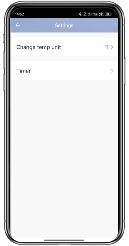
Celsius and Fahrenheit switch
Manual defrost
Under the main interface of shutdown state, long press and for 5 seconds to restore the value of unit user parameters and factory parameters to the default state of factory parameters.
Under the main interface, press and for 3 seconds to switch Celsius and Fahrenheit.
When the unit is under heating mode or auto mode, press and key for 3 seconds, the defrost mode will be started.
4.2. Parameter List
4.2.1. Temperature Status Query.
T1 Exhaust temperature
T2 Suction temperature
T3 Water outlet temperature
T4 Cooling coil temperature
T5 Heating coil temperature
T6 Ambient temperature
1F EEV steps
Press for 3 seconds to enter parameter query, and then press or to check the data
od Operation mode 0: OFF/Standby
Code Parameter
Remark
1: Heating 2: Cooling
OF Fan motor status ON OFF
dF Defrosting state
STF Four-way valve status
Pu Water pump status
HE1 Failure code history 1
HE2 Failure code history 2
HE3 Failure code history 3
HE4 Failure code history 4
Pr Main board software version
Sr Display software version
4.2.2. Parameters
Code
Press for 3 seconds to directly enter, then press and to query the parameters
L7 Water pump working mode
L8
L9
4.3.
4.4.
0:The water pump is not stopped during constant temperature shutdown.
1: When shutting down at constant temperature, the water pump delays the compressor to turn off for 60 seconds.
Every (L8) minutes open 5 minutes 0
The running interval of the water pump when shutting down at constant temperature 3
Sterilizer mode (This function is only available for the chillers equipped with sterilizer.)
Code
Fault Description
E01 Exhaust temperature sensor failure
E05 Heating coil temperature sensor failure
E09 Suction temperature sensor failure
E19 Cooling coil temperature sensor failure
E18 Water outlet temperature sensor failure
E21 Communication failure between display and main board
E22 Ambient temperature sensor failure
P01 Water flow protection for circulation pump
P02 High pressure protection
P06 Water flow protection for self-priming pump
P11 High exhaust temperature protection
P17 Anti-freezing protection
P23 Low water outlet temperature protection for cooling
P25 Low/high ambient temperature protection
P26 High water outlet temperature protection for heating
1.Loose wiring or poor connection of high pressure switch
2.There is something wrong with high pressure switch
3.Main board is broken
4. Poor condensing
4.1 Water temperature is too high (over range operation).
1 High pressure protection
2
Water flow protection
4.2 Low water flow
4.2.1 The valve in water system is not open.
4.2.2 Waterway blockage, may appear in the heat exchanger or valve part.
4.2.3 Improper water pump selection
4.2.4 The water pump is broken .
5. Refrigerant system blockage, may appear in the throttle part.
6. Refrigerant system is mixed with air, maybe the vacuum is not enough.
1. The connection between water flow switch and main board is poor.
2. The water flow switch is installed wrong.
3. Water flow switch failure.
4. Main board failure.
5. Low water flow
5.1 The water system is blocked.
5.2 Water pump is not suitable
5.3 Water pipe is small
5.4 The water flow switch is stuck and cannot be reset.
6. No water flow
6.1 The valve is not open.
6.2 The water pump is not working.
6.3 Water pump failure.
1. Reconnect the wire.
2. Replace the high pressure switch.
3. Replace the main board.
4.1 Operate within the allowable range.
4.2.1 Open the valve.
4.2.2 Clean the blocked part or replace it .
4.2.3 Change the pump according to the water flow and water head.
4.2.4 Replace the water pump.
5. Clean or replace the clogged part.
6. Vacuumize and refill the refrigerant.
1. Reconnect the water flow switch cable
2. Install the water flow switch in the correct way.
3. Need to replace the water flow switch
4. Need to replace the motherboard
5.1 Clean or replace the blocked part.
5.2 Change the pump according to the water flow and water head.
5.3 Need to change the water pipe.
5.4 Reset the water flow switch manually.
6.1 Open the valve.
6.2 Turn on the pump.
6.3 Need to replace the water pump.
3
Exhaust protection
1.Temp.sensor fault.
2.Water flow switch fault
3.Leakage happen,and refrigerant is not enough .
4.Low water flow
4.1 The water system is blocked.
4.2 Water pump is not suitable
4.3 Water pipe is small
4.4 The water flow switch is stuck and cannot be reset.
5. No water flow
5.1 The valve is not open.
5.2 The water pump is not working.
5.3 Water pump is broken .
1.Poor condensing
1.1 Water temp. is too high (over range operation).
1.2 Low water flow
1.2.1 The valve in water system is not open.
4
5
Over-current protection
Ambient/Inle
t/Outlet/Exha
ust/Suction/ External coil/Internal coil/sensor fault
6 Communicat ion fault
1.2.2 Waterway blockage, may appear in the heat exchanger or valve part.
1.2.3 Improper water pump selection
1.2.4 The water pump is broken .
2.Refrigerant system is mixed with air, maybe the vacuum is not enough.
3.The water pipe is blockaged.
4.The valve opening steps not enough.
5.Excessive refrigerant.
6.The fan is blockaged.
1. The connection between the temp. sensor and the main board is poor.
2. Temp. sensor fault.
3.The sensor resistance on the main board fault.
1.The connection between wire controller and main board is poor.
2.Wire controller fault.
3. Main board fault.
4. Communication wire and strong electricity wire put together, resulting in power interference communication
1.Need to replace the temp.sensor.
2.Need to replace the water flow switch.
3.Repair the leakage,and refill the refrigerant according to the nameplate.
4.1Clean or replace the blocked part.
4.2 Change the pump according to the water flow and water head.
4.3 Need to change the water pipe.
4.4 Reset the water flow switch manually.
5.1 Open the valve.
5.2 Turn on the pump.
5.3 Need to replace the water pump.
1.1 Operate within the allowable range.
1.2.1 Open the valve.
1.2.2 Clean the blocked part or replace it .
1.2.3 Change the pump according to the water flow and water head.
1.2.4 Replace the water pump.
2. Vacuumize and refill the refrigerant according to the nameplate.
3. Clean or replace the water pipe.
4. Turn the valve up appropriately.
5. Bleed out the refrigerant and refill the refrigerant according to the nameplate.
6. Clean out the blockage from the fan or replace the fan.
1.Reconnect the temp.sensor cable.
2.Replace the temp.sensor.
3.Replace the main board.
1. Reconnect the wire controller cable.
2. Replace the wire controller.
3. Replace the main board.
4. Communication wire is placed separately from the strong electricity wire.
7
Anti-freeze protection
1. Low ambient temp. running.
2. Low water temp.
1. When the ambient temp. is ≥ 2°C, exit the anti-freeze state.
2.When the inlet water temp. > 15°C, exit the anti-freeze state.
1. Power outage
2. Power switch is not connected
1 Unit is not running
2 Unit is not running after starting up
3. Power switch fuse is burnedout
4. Timing is not up
1. Compressor protection time interval is not up
2. Water temp. of the unit does not reach starting up water temp. value
1. Please wait for power supply recovery
2. Connect power
3. Replace fuse
4. Please wait or cancel timing setting
1. Please wait patiently for the end of protection time
2. Normal phenomenon and wait for water temp. to reach
3 Unit is running normally, but can’t get the demand water temp.
1. Improper temp. setting
2. Filter element is dirty
3. Air inlet port or outlet port of outdoor machine or indoor machine is blocked
4 Unit is running automatically Reach timing to start up
1. Set up proper temp.
2. Replace the filter element
3. Clear tuyere obstruction
Please shutdown manually or cancel timing if needn’t start up
4.6. Wi-Fi Settings
4.6.1 Software Installation
① Method 1: Search ”Smart life” in your APP store ,install “ ”.Click “GET” to install.


② Method 2: Scan the QR code below.

For IOS and Android Users
4 6.2 Software Startup
After installation,click “ ” on your desktop to start up Smart Life.
4
1. Registration

① Users don’t have account can click “Register” to create an account: Register Enter your phone
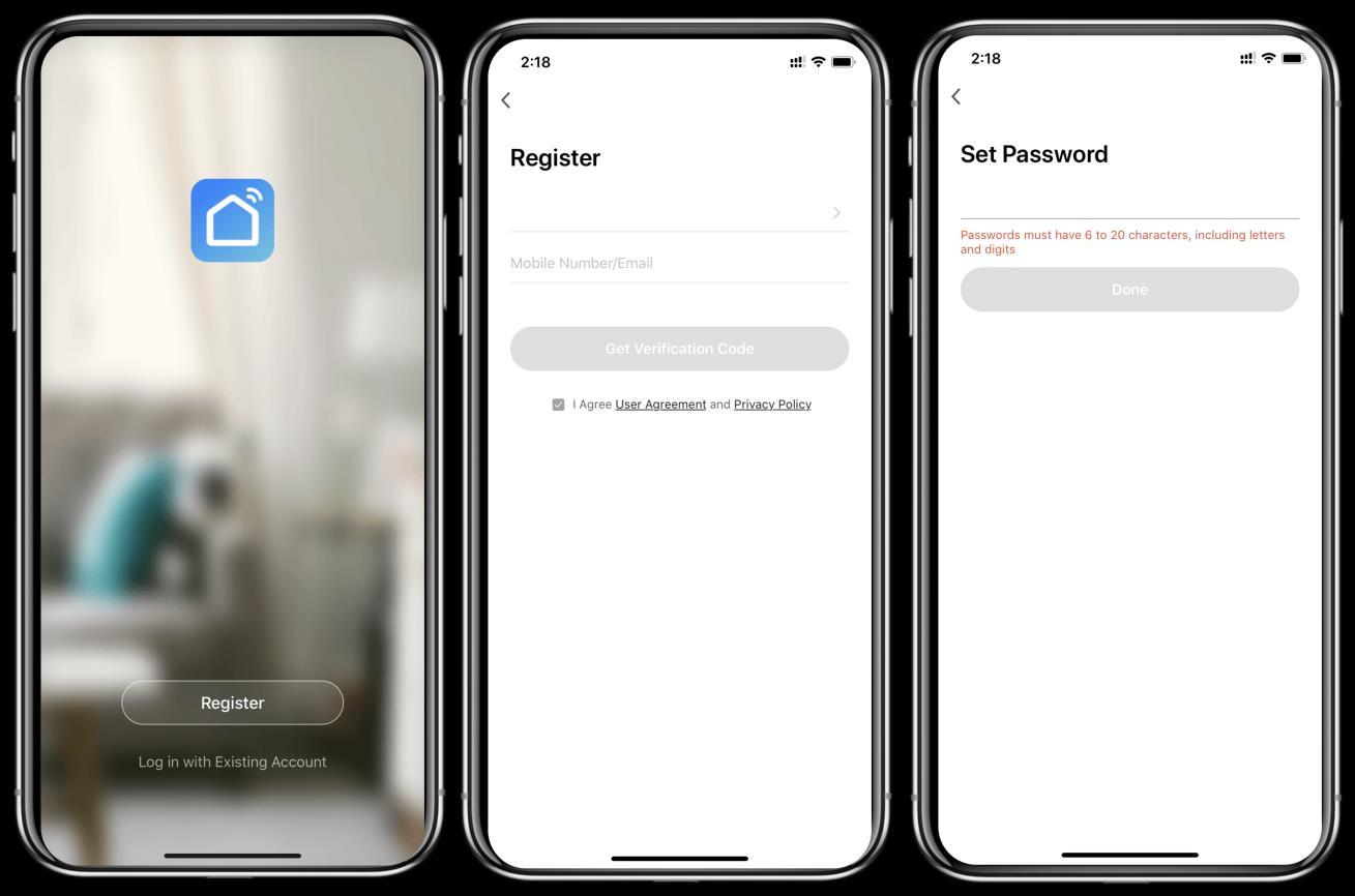


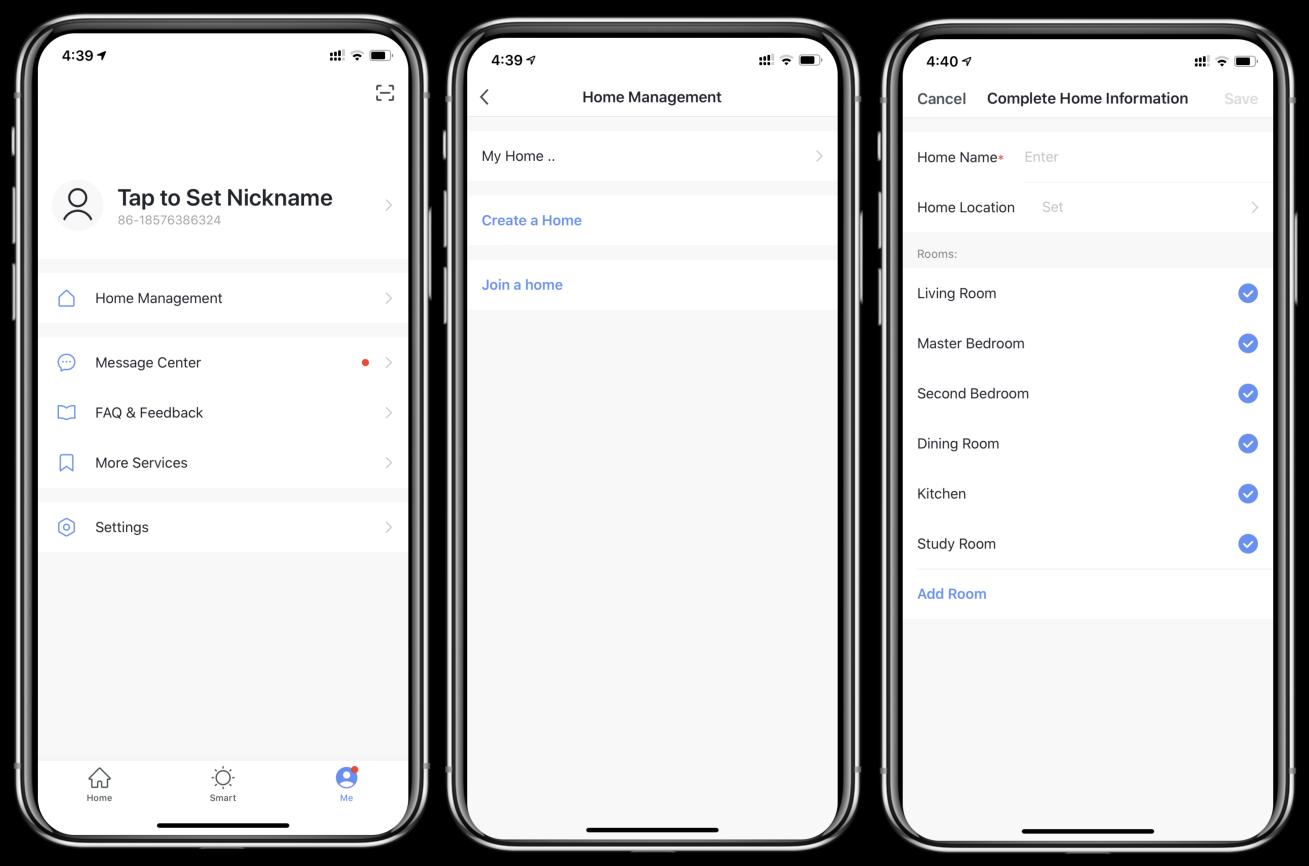
② After registration, you need to Create a Home:Create a Home Set Home Name
Set Home Location Add Rooms.


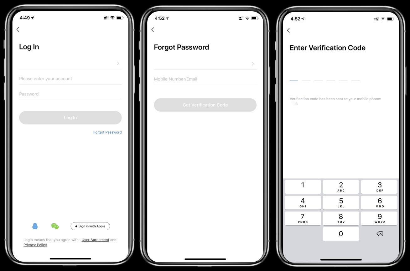
① Existing accounts can be logged in directly, in the following order.
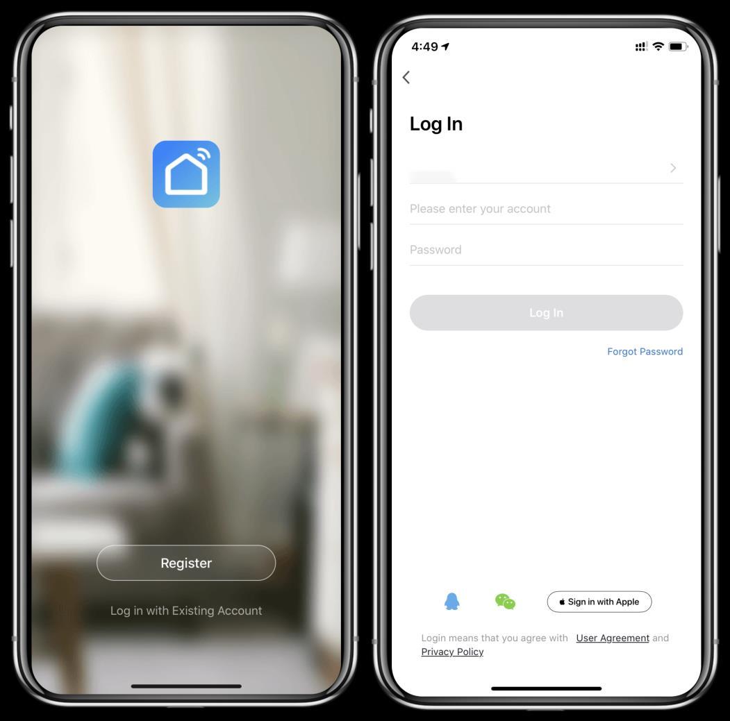
② If you forget your password you can choose to login with your verification code and select "Forget Password": Enter your phone number Get verification code .
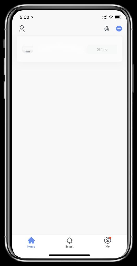
③ After creating a home or logged in,enter the main interface of APP.
Note:
Click the device to check the status, and you can set the operating mode, ON/OFF, timer. Click “+” to add devices.
3. Wi-Fi Module configuration steps:
Step 1:
When power is on, press and hold the " " and " " keys at the same time for 3 seconds to enter the distribution network. The " " icon will flash rapidly;.
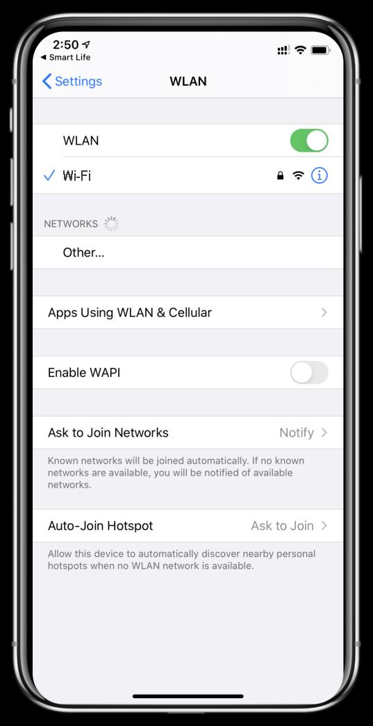
Step 2:
Turn on the phone's Wi-Fi function and connect to the Wi-Fi hot-spot. The Wi-Fi hot-spot must be able to connect to the Internet normally;
Step 3:
Open the "smart life" APP, log in into the main interface, click on the top right corner "+" or "add equipment" of the interface, enter the equipment type selection, the "Large Home Appliances" , select "Smart Heat Pump" equipment and add equipment into the interface.
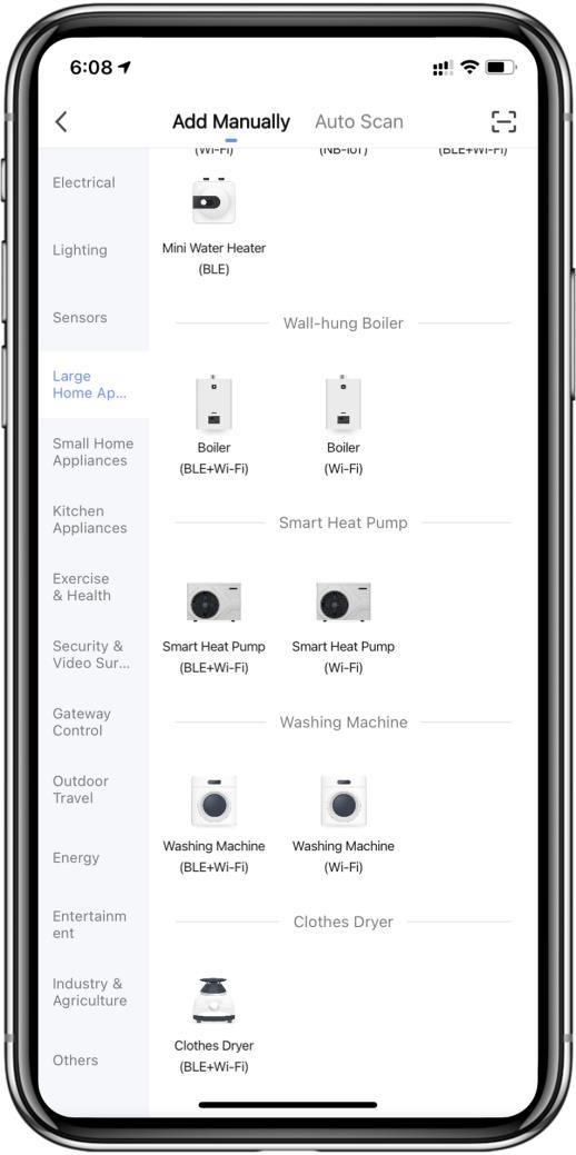
Step 4:
After selecting "Smart Heat Pump", enter the interface of "Add Equipment", after the indicator light under " " flashes rapidly , click" Confirm indicator rapidly blink ".
Enter the Wi-Fi connection interface, enter the Wi-Fi password of the mobile phone (it must be the same as the Wi-Fi of the mobile phone), click "Next", and then directly enter the connected status of the device
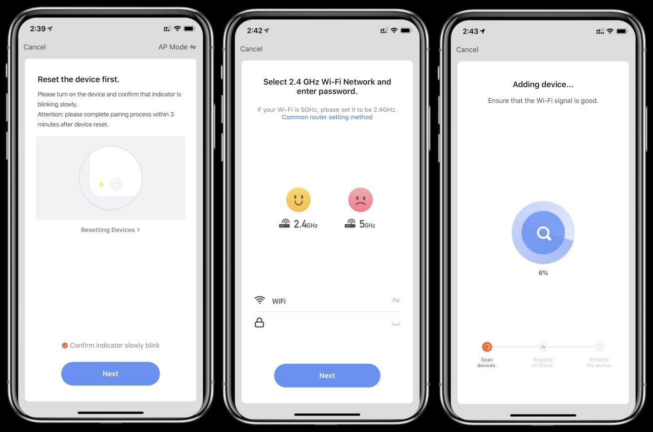
Step 5: When “Scan devices”, “Register on Cloud”, “Initialize the device” are all completed, connect succeeds
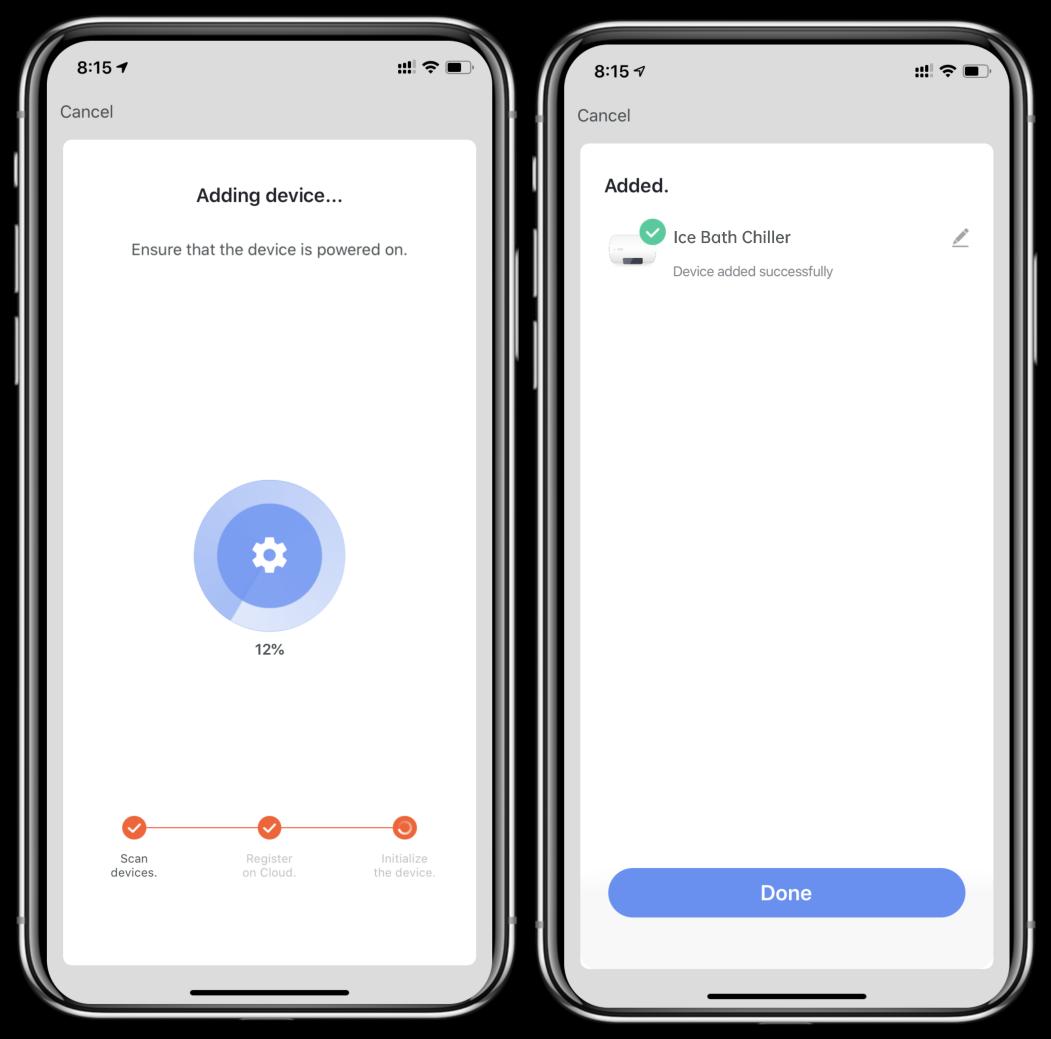
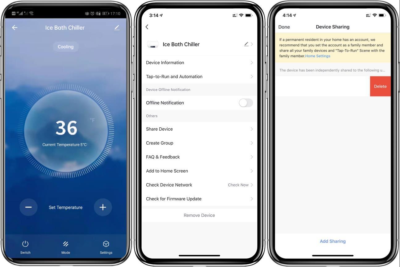
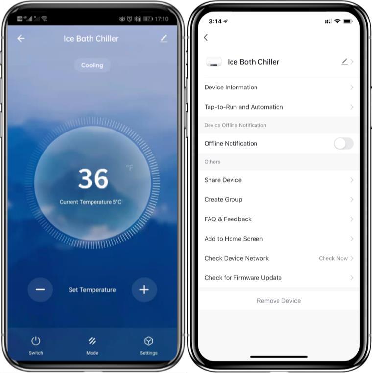
⚫ After the device is bound successfully, enter the operation interface of “Smart heat pump” (Device name, modifiable)
⚫ In the main interface of “Smart Life”, click “Smart heat pump” to enter the operation interface.
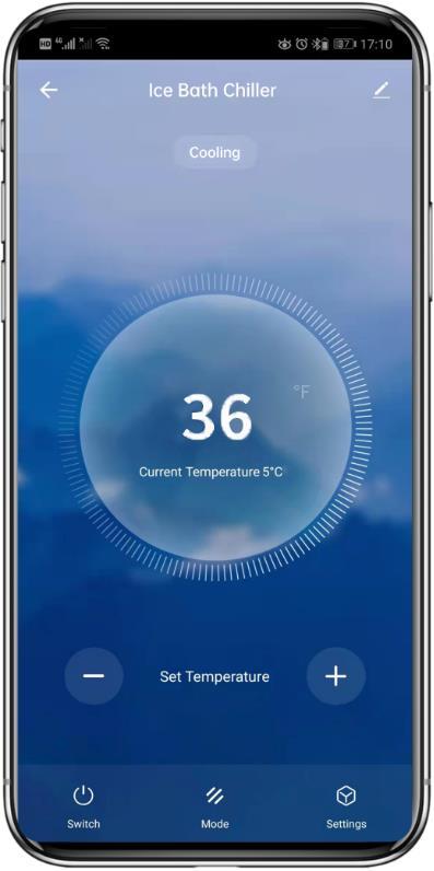


② More: You can change device name, select device installation location, check networking status, add shared users, create device cluster, view device information, and more.
③ Setting temp. adjustment: The circle slides counterclockwise to reduce the temp., but clockwise to increase the temp..
④ Target temp.
⑤ Current temp.
⑥ ON/OFF
⑦ Mode switching: Click to select the mode to be switched.
⑧ Timer: Click to add timer off/on time.
⚫ Modify device name
Click in the following order to enter device details, and click "Device Name" to rename the device.

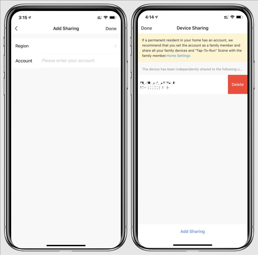
⚫ Device sharing
◆
To share a bound device, the user should do so in the following order.
◆ After successful sharing, the list will be added to show the person shared
◆ If you want to delete the account you shared to, cross the selected account to the left,and delete it.
◆ The user interface is as follows
◆ Enter the account of the shared, click "Done", and the share success list shows the newly added account of the Shared.
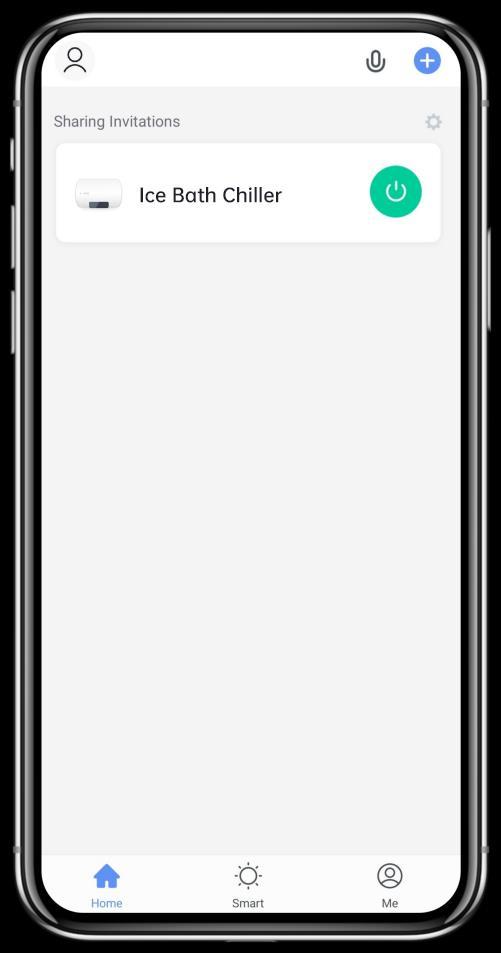
◆ The interface of the person to be shared is as follows. The received shared device is displayed.
Click it to operate and control the device.
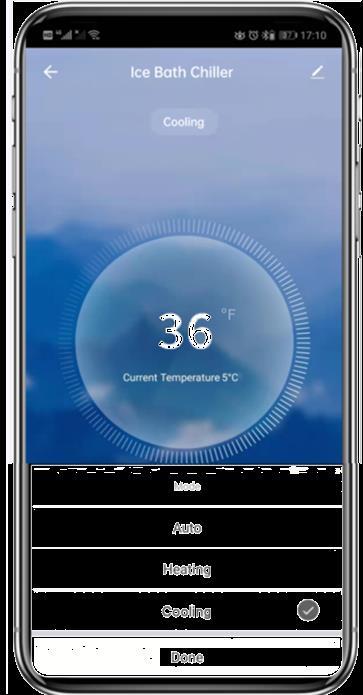
⚫ Mode settings

Click “ ” on the main interface to switch modes,select what you need.
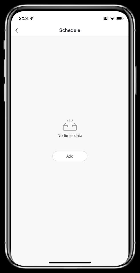
1.Click “ ” on the main interface to enter the setting interface, then click “Timer” to add timer.

1.After entering timer setting, swipe up/down to set timer,set up repeat weeks and on/off,then click “save” to save your settings as follows.
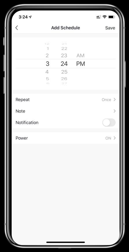
① Hours
② Minutes
③ Set the repetition
④ Set power ON/OFF
⑤ Save your modification
4.6.5 Device Removal

Click “ ” on the top right corner of the main interface to enter the device details interface, and click “device removal”. Indicator light under“ ” flashes rapidly for 3min, The network can be reconfigured within 3 minutes, and the network can be quit if it is not connected within 3 minutes. The specific operations are shown as follows.
5.1
WARNING:Before undertaking maintenance work on the unit, ensure that you have disconnected the electrical power supply.
⚫ Cleaning
a. The bath chiller’s casing must be cleaned with a damp cloth. The use of detergents or other household products could damage the surface of the casing and affect its properties.
b. The evaporator at the rear of the bath chiller must be carefully cleaned with a vacuum cleaner and soft brush attachment.
⚫ Annual maintenance
The following operations must be undertaken by a qualified person at least once a year.
a. Carry out safety checks.
b. Check the integrity of the electrical wiring.
c. Check the earthing connections.
d. Monitor the state of the pressure gauge and the presence of refrigerant.
Tools:
① Phillips screwdriver
② Wrench
③ Flat-blade screwdriver
Step one:Take out the service plate (for filter and UV lamp replacement)
① Press the spring latch
② Pull out the service plate
③ Lift up to take out the service plate
As the following figure shows

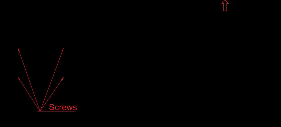
Step two:Take out the back net
① Take out the two screws
② Press and hold the back net, then slide down
③ Pull out the back net
As the following figure shows

Step three:Take out the shell
① Remove the screws as shown
② Lift up the shell
③ Disconnect the cable between main board and wire controller
④ Take out the whole shell
As the following figure shows

Step four: Take out the electric box cover
① Remove the four screws on the electrical box cover
② Lift it up and take out the electric box cover
As the following figure shows
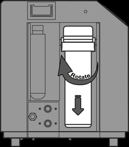
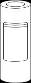
⚫ If used frequently, it is recommended to replace the filter element every three months
⚫ It is recommended to check the filter element every month. If the filter element is dirty, it needs to be replaced according to the following steps:
Use the included wrench to unscrew the filter bottle downwards and replace the filter element inside.
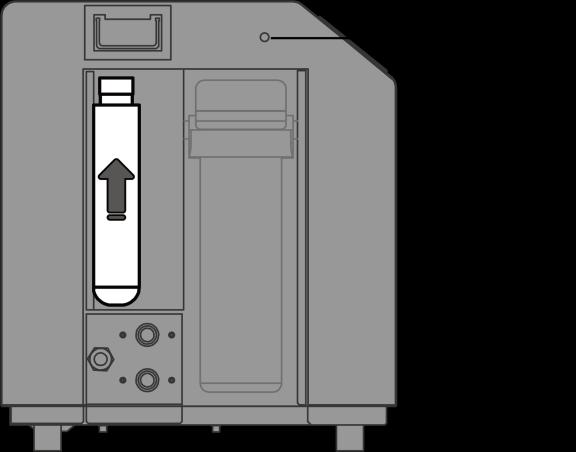
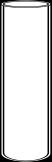
⚫ lf the UV lamp indicator turns red, pleas change the UV lamp as following steps:
Pull the upper part of the UV out of the slot, unscrew the top cover, and replace the light tube inside
"CUT OFF"power supply of the heater before cleaning, examination and repairing
In winter season when you don’t use the bath chiller:
a. Cut off power supply to prevent any machine damage.
b. Drain water clear of the machine.
!! Important:
Unscrew the drain plug to let the water flow out. When the water in machine freezes in winter season, the titanium heat exchanger may be damaged.
c. Cover the machine body when not in use.
1.013.001.0046