User Manual Beforeoperatingthis product,pleasereadtheinstructionscarefullyandsavethismanualforfutureuse. www.hottubsuppliers.com
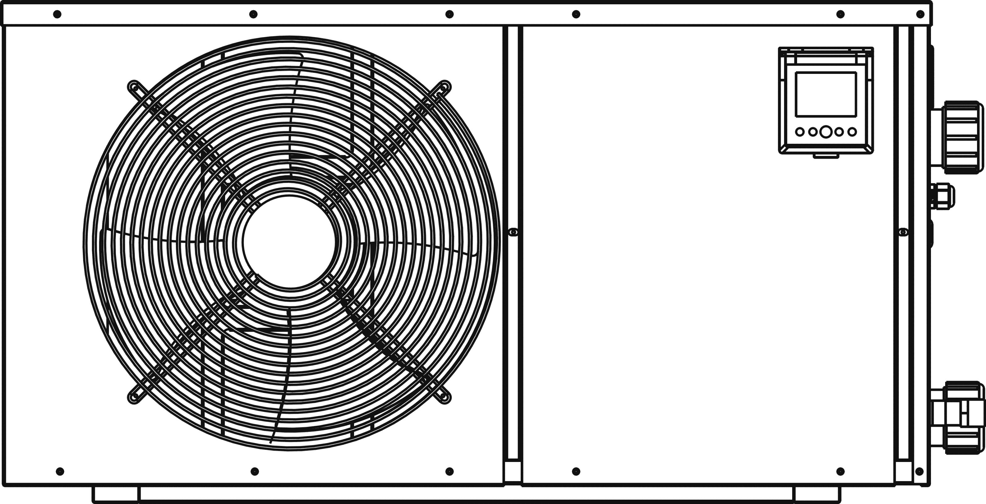
The Eco Spa Heat Pump

Cleanthemachinebywashingwith detergentandwateratlowpressure,and thenrinsingwithcleanwater.
Theinstallation,commissioningandmaintenance ofthesemachinesshouldbeperformedby qualifiedpersonnelhavingagoodknowledgeof standardsandlocalregulations,aswellas experienceofthistypeofequipment.
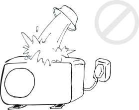
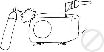
Donotspreadoveranypaint orinsecticidal materialonthesurfaceoftheunit.
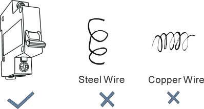
Itistheresponsibilityofthe installertoprovide circuitbreakerprotection,correspondingtothe machine’scapacity(refertotheunitelectrical characteristicstable),neartothemachine.
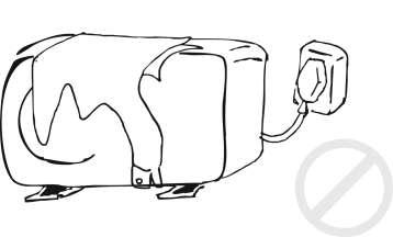
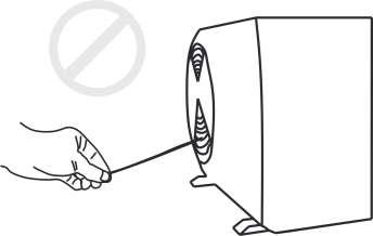
Donotblocktheevaporatorbypaperoranyother foreignbodies,tokeeptheunitwellventilated.
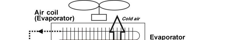
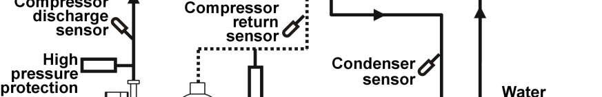
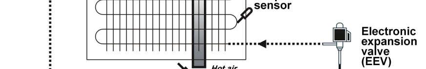
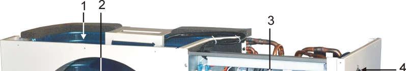
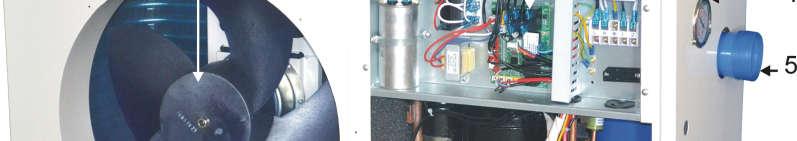
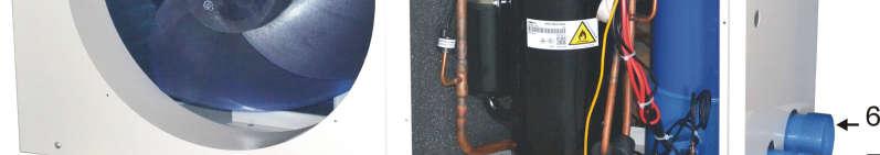
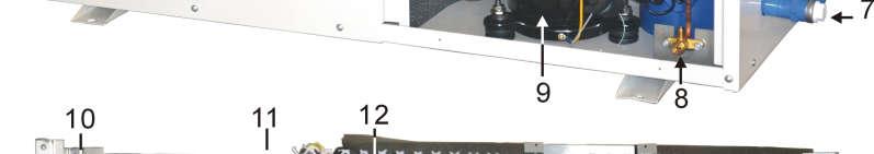
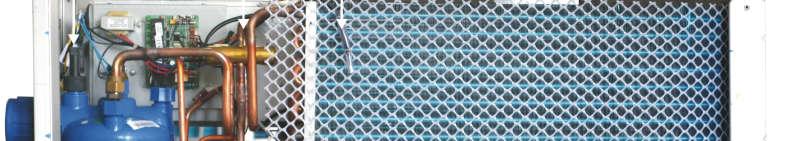
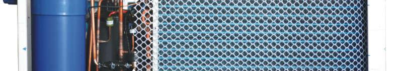
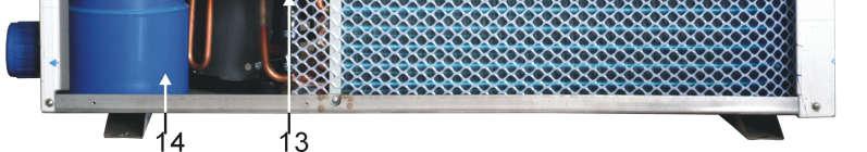
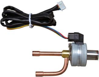
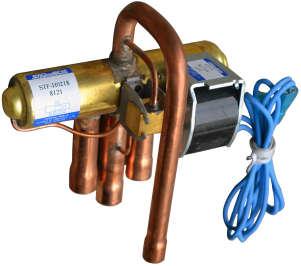
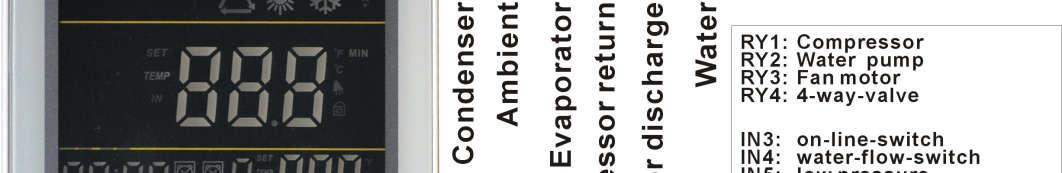
The refrigerant system consists of 5 main components: compressor, 4-way-valve, titanium heat exchanger (condenser, refrigerant to water), electronic expansion valve/capillary, evaporator (air to refrigerant).
Heatpumpcanabsorbtheheatingfromairsource.Thismakestheheatpumpavery environmentallyfriendlyandeconomicallysoundalternativeforspaceheating.
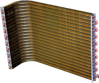
*Evaporator:lowtemperature,lowpressurerefrigerantgothroughevaporator,toboilandturn fromliquidtogas.Refrigerantabsorbheatingfromairsource.
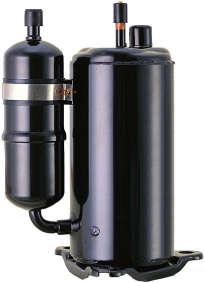
*Compressor:compressorabsorbrefrigerant,andcompresstohightemperature,highpressure status.
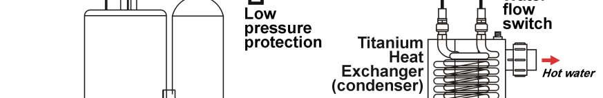

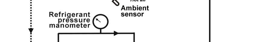
*Condenser:refrigerantreleaseheatenergytowater.Refrigeranttemperaturereduces,andit returnsfromgasstatustoliquidstatus.
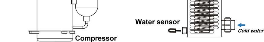
Theheatenergyisabsorbedbywater,circulatedbyacirculationpumptopool.

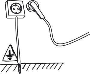
NOTE: although the unit heat exchanger is electrically insulated from the rest of the unit, this simply prevents the flow of electricity to or from the pool water. Grounding the unit is still required to protect you against short circuits inside the unit.
NOTE: ensure that the available electrical Power supply and the network frequency are matched to the required operating current, taking account of the appliance’s specific location and the current required to supply any other appliances connected to the same circuit.
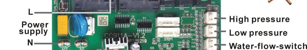
1)Seethewiringdiagram;
2)Ensurethattheunitissuppliedwiththespecifiedvoltage.Theterminalblockislocatedonthe rightsideoftheunit.TherearethreeconnectionsforthePowersupplyandtwoconnectionsfor thefilteringpumpcontrol(Enslavement).ThePowersupplylinemustbeproperlymatchedwitha motor supply type fuse or a main circuit breaker to protect the circuit against voltage surges (refer to the nameplate for the voltage);
3) Always shut down the main Power supply before opening the electrical control box.
The assembly, the electric connection and the start up must be carried out by specialized and professional person.
Whenconnect plugtosocket(powersupply),pleasemakesurethatlivewire,neutralwire,earth wiretoplugshouldbeconnectedasrightdrawing.
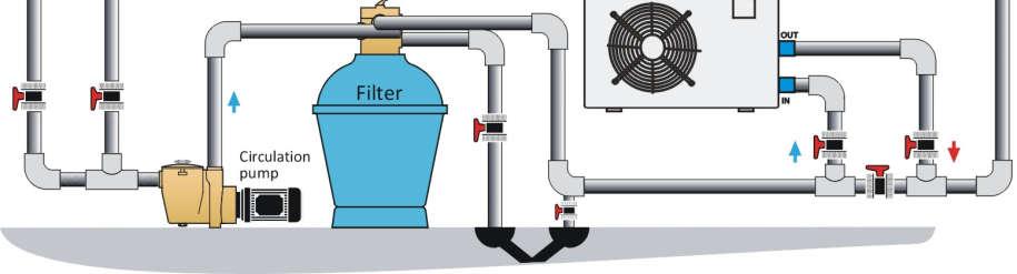
Whenheatingisneeded:
MakevalveAopen,andthenkeepthewaterinletandoutletTempdifferenceat2℃ by adjustingtheopenofvalveC.
Whenheatingisnotneeded:

MakevalveAandvalveCfullyopen,sothewatercanbecirculatedthroughthefilteronly. Whendisinfectionisneeded:
MakevalveAclosedandvalveBopen,toguidethewatergothroughthechlorine.
Inordertoproperkeeppowerconsumptionlowandtocomplywithstandardsinforce,allhot waterpipesmustbeinsulated.
Pleaseensurethewaterflowinsidetheunit.
No smaller than 80% of the rated water flow.
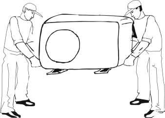
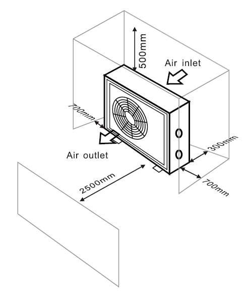
1.heat pumpmustinstallonaflat,solid,preferably cementedsurface.
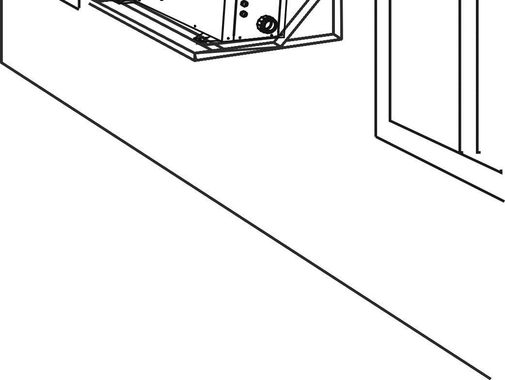
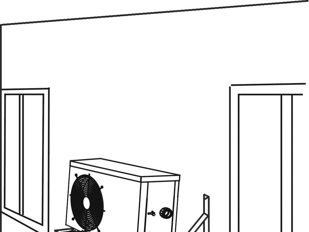
2.wheninstalltheheatpumpinharshclimaticarea, sub-zerotemperatures,snow,humidity…,itis recommendedtoraisetheunitovertheground50cm.
3.rubbervibrationabsorbingmountingsarerecommended.
4.duringinstallation,makesuresufficientfreespace aroundtheheatpumpforfuturemaintenance.
5.theunitisaircooled.Itmustbeinstalledoutdoorinan areawithsufficientclearancetoprovideenoughair circulationthroughevaporator.
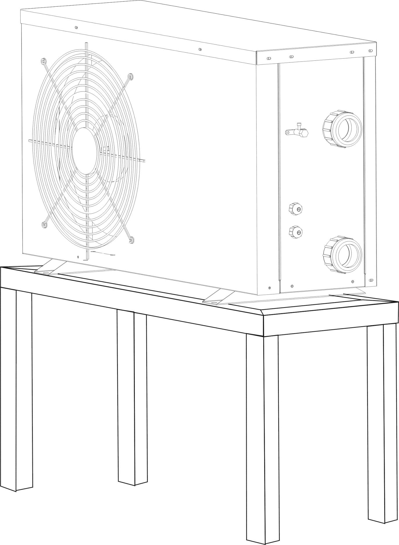
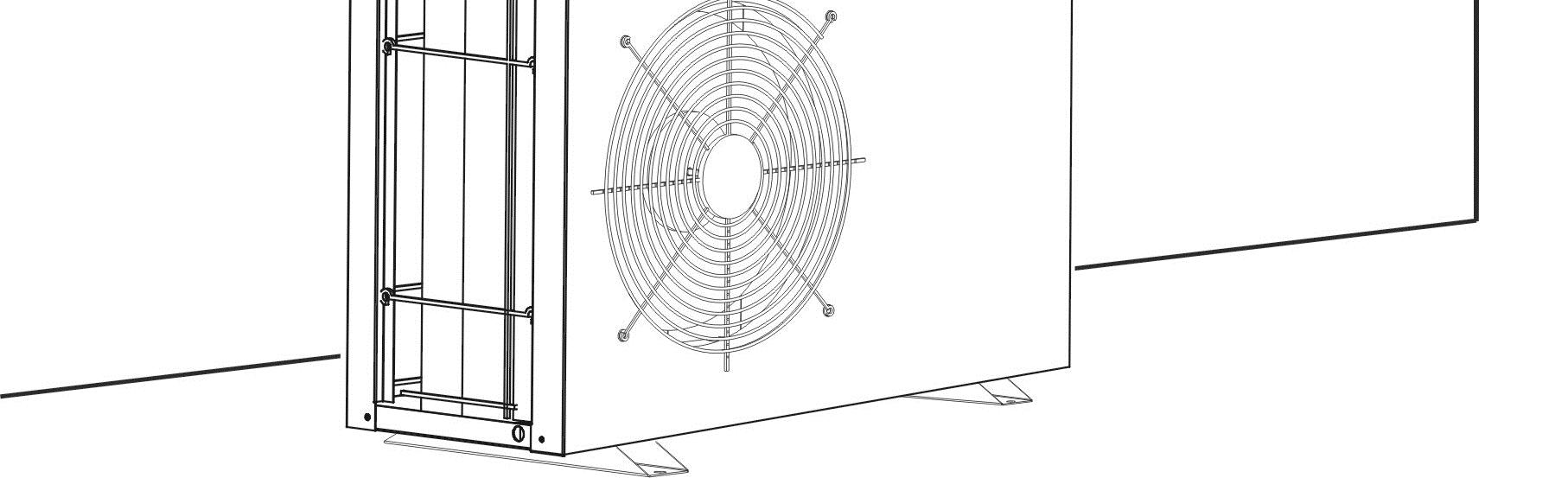
6.shieldtheunitfromdirectsunshineorrain,butnever blocktheairventilation.
7.theunitshouldbefreefromexplosiveandcorrosivegas, andgrease.
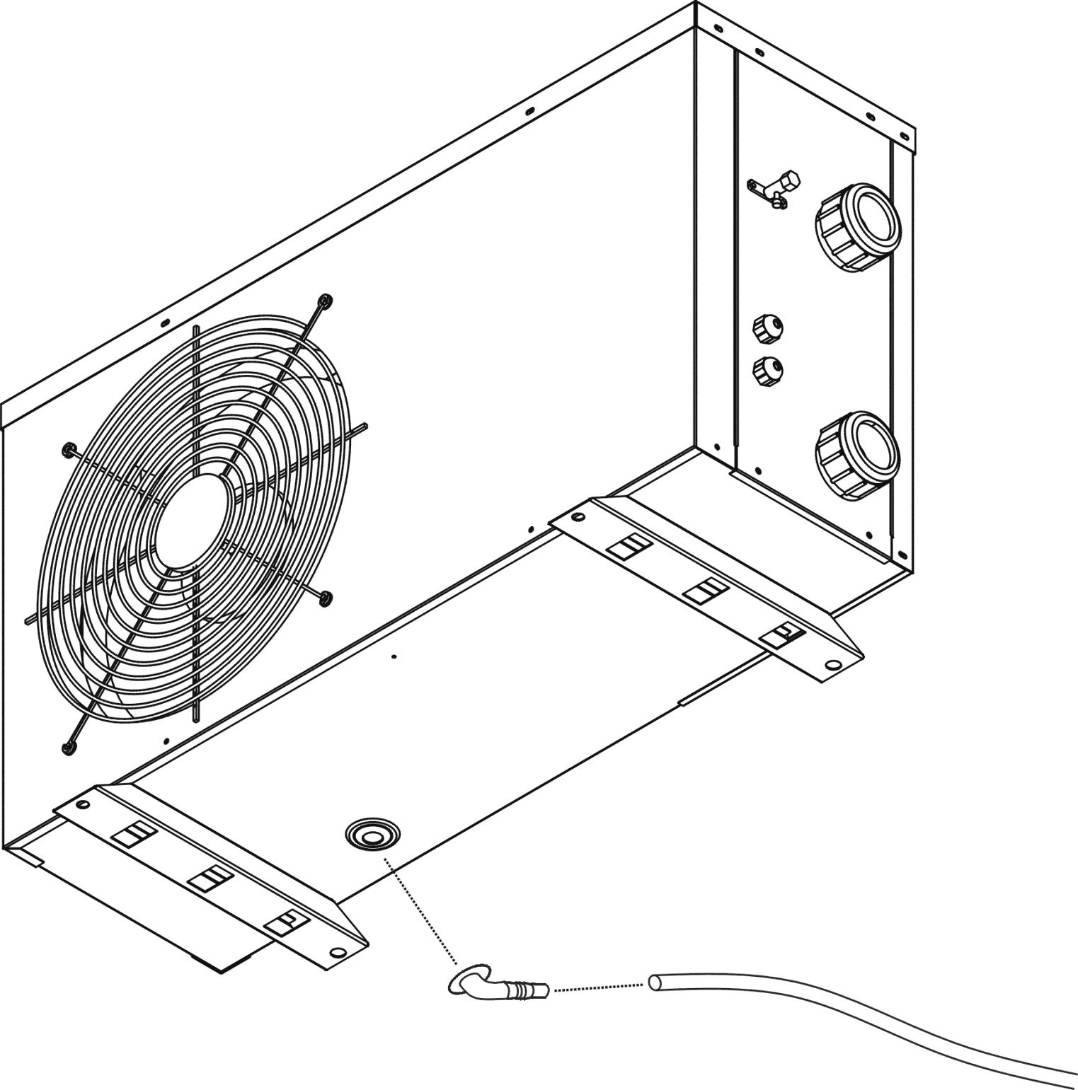
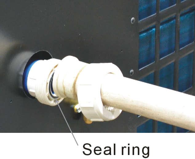
Please install the drain connector as shown in the picture when necessary. In some cold areas ( ambient temperature below 0’c ), please do not use the drain connector, otherwise it may clogged by ice.
The water from swimming pool heat pump should already pass by a filter before entering the unit. Some dirt perhaps damage or choke the Titanium / PVC heat exchanger and cause some failure.


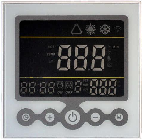
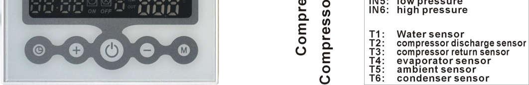
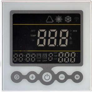
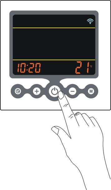
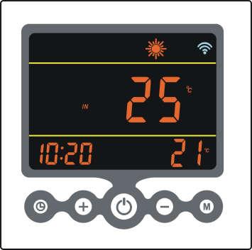
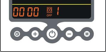
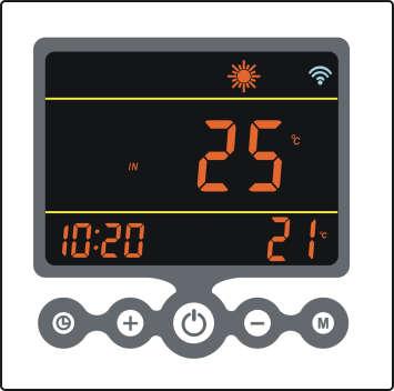
When Heat Pump is Off
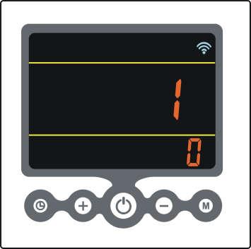
WIFI symbol

Current Clock


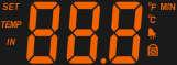
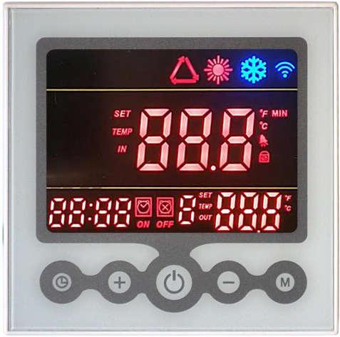
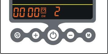
When Heat Pump is On
Heating Mode
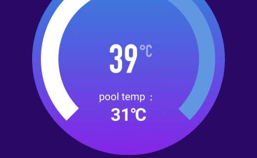
Current Water Temperature
Press or To Change Set Temp.
Ambient Air Temperature
Press to Start Heat Pump
Press To Other Mode
When On
Hold 6Sec To Release Key Lock.
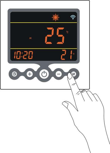


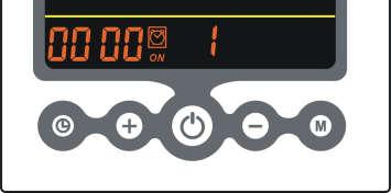


Hold 6Sec To Parameter Setting.
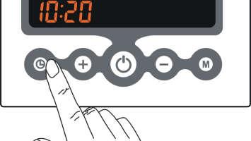
Press
Press
To Next Parameter. To Edit Value ( 1 flash ).
Press or To Change Value.
Press To Exit Parameter Setting.
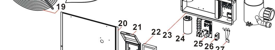
22 Reserve
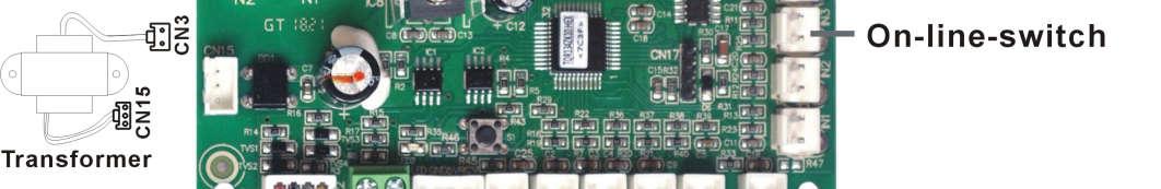
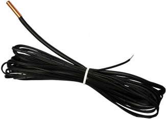
23Evaporatorsensor
24Compressordischargesensor
25 Ambient sensor
26 Compressor return sensor
27EEVstep
28Condensersensor
4.7 Mode
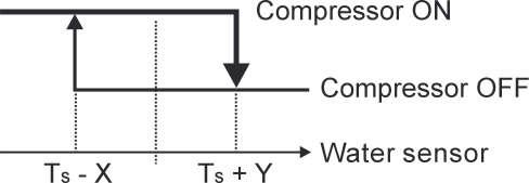
4.7.1 Heating Mode: Display ( 4-way-valve switch Off )
Parameter Setting:
P2TemperaturedifferentX
P3TemperaturedifferentY
P9MaxsettemperatureforHEATINGmode
Ts(Settemperature)range:15°C~P9
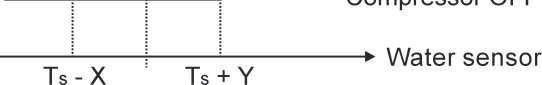
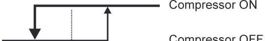
4.7.2 Cooling Mode: Display ( 4-way-valve switch ON )
Parameter Setting:
P2TemperaturedifferentX
P3TemperaturedifferentY
Ts(Settemperature)range:8°C~28°C
4.7.3 Auto Mode: Display ( 4-way-valve switch ON )
Parameter Setting:
P2TemperaturedifferentX
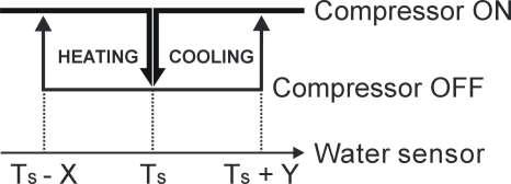
P3TemperaturedifferentY
P9MaxsettemperatureforHEATINGmode
Ts(Settemperature)range:15°C~P9

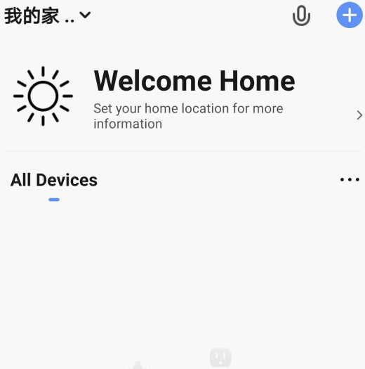
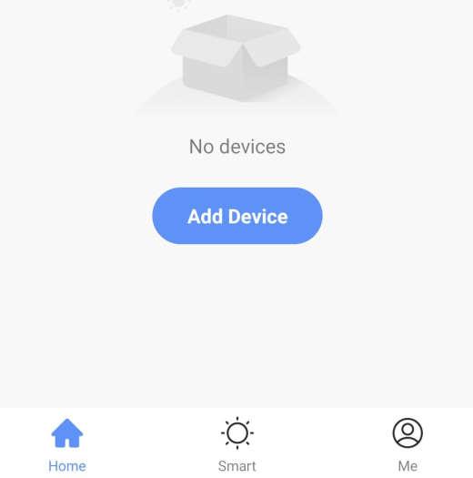
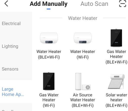
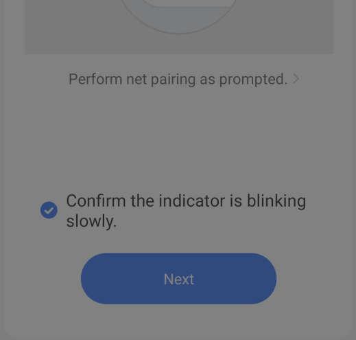
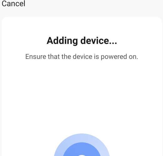
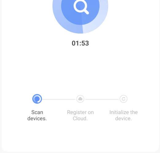
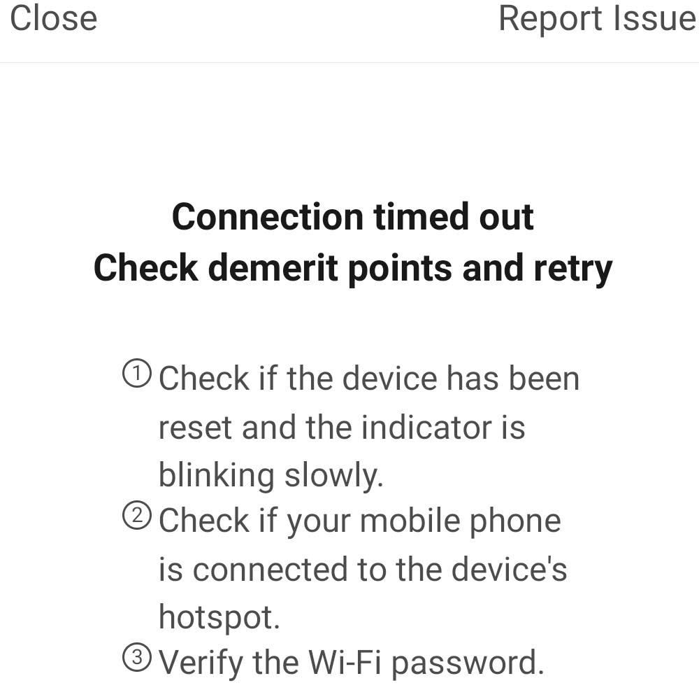
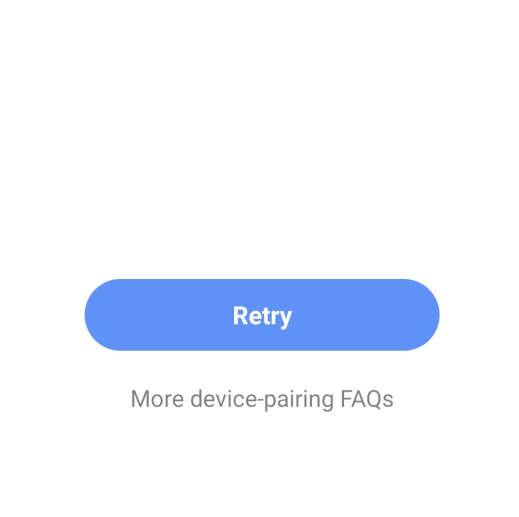
The internet access module install at controller. Controller connect to server by your current Wifi. Install controller where can access your current Wifi. You have to put your mobile and controller at same place during installation.


Parameter Setting:
P4 Defrost period
P5 Defrost start temperature
P6 Defrost exit temperature
P7 Max defrost running time
●Startofdefrost:
Thedefrostwillstartwhenallfollowingconditionsarefulfilledatthesametime:
-evaporatorsensorrature≤-4°C (parameterP5)
If evaporator sensor malfunction ( error P3 ), defrost change to TIMER defrosting, defrost running time 8 minutes.
- compressor continue to runs 40 minutes ( parameter P4 )
●Actionofdefrost:
-compressorandthefanstop
-25seconds,4wayvalveswitchON.
-30seconds,compressorstarts,andhotrefrigerantwillenterintoevaporator,theiceon evaporator will be melt, that is generally with a steam.
- water pump continue to run when defrost
●Stopofdefrost:
defroststopwhenoneofthefollowingconditionsisfulfilled:
-evaporatorsensor≥12°C (parameterP6)
-compressorruntotally8 minutes (parameterP7)
●Actionofexistdefrosting:
-compressorstop,fanrun
-25seconds,4wayvalveswitchOFF
-30seconds,compressorrun
If not necessary, please do not change defrosting parameter setting.
1.Whenunitstart,waterpumprun90secondsbeforecompressorrun.
2.Whenunitstop,waterpumpstop30secondsaftercompressorstop.
3.Waterpumpcontinuetorunduringdefrost.
4.Parameter10=0:waterpumpcontinuetorunwhenreachtosettemperature
Parameter10=1:waterpumpstop30secondsaftercompressorstop, andstop10minutes(parameterP11=10minutes),run2minutes.
5.WhenunitOFF,waterpumpstop12hours,run2minutes.
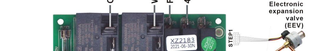
Initialstep:350
steprange:(parameterP18)~500
After unit start, EEV first reset, opens 520P, then adjusts to initial opening of 350P;
Compressorexdischargetemperature:Te
Compressorreturnairtemperature:Tr
Evaporator: Te
Condensertemperature: Tc
WhenTe≥95°C(parameterP16),EEVincrease20stepeachtime. WhenTe<95°C(parameter16),EEVstepcalculatebybelow:
EEVstepaction:
Aftercompressorstart,EEVstepactioncalculatebybelow (maxstepperactioncyclelimitwithin±20P):
EEV step opening change ▽P = KP* (actual average superheat SH - target superheat TSH) P=P(initialopening)+ ▽P; WhenSHaverage≤-1,KP=3; When-1<SHaverage≤0,KP=2; WhenSHaverage>0,KP=1;
SH:Calculatedvalueofsuperheat, SH= TS - TC/TE; (SH=return sensor - evaporator sensor in HEATING, SH=return sensor - condenser sensor in COOLING )
SH average: average value of actual superheat within 45S, record every 5S
TSH: Target superheat
P: The actual opening of EEV
Determination Of Target Superheat TSH : 0°C (parameter P15);
EEV Step Action Period : change every 45S (parameter P14)
When Defrost, EEV step: 400 (parameter P17).
The evaporator does not require any special maintenance, except when it is clogged by paper or any other obstacle. Clean with washing detergent and water.
1.Before cleaning, make sure that heat pump is power OFF.
2.Inside of heat pump must be cleaned by qualified person.
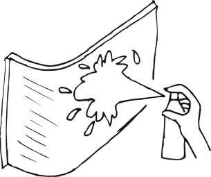
3.Do not use gasoline, benzene, detergent etc. to clean the heat pump. Do not spray with insecticide, the unit may be damaged. The cleanser special made for air conditioner cleaning is recommended.
4.Spray air conditioner cleanser into the evaporator, let the cleanser sit for 5~8 minutes.
5.Then, spray the evaporator by clean water.
6.An old hairbrush works well for brushing surface dirt and lint off the fins. Brush in the same direction as the slots between the fins so the bristles go between the fins.
7.After cleaning, use a soft and dry cloth to clean the unit.
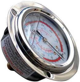
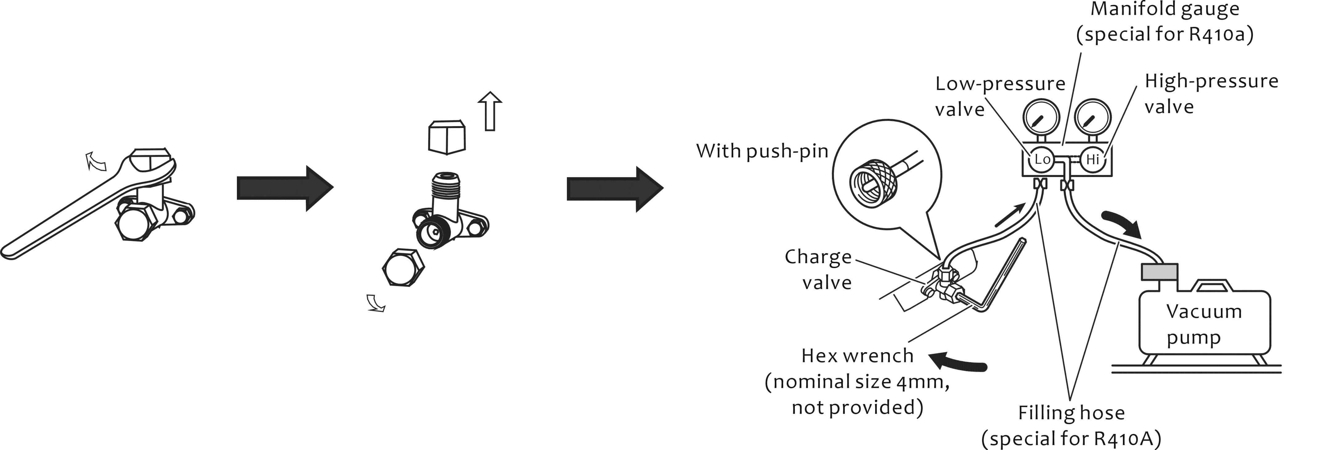
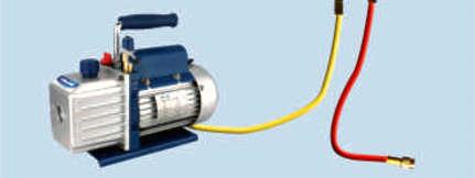
Removethecoppernut.Connectthepressuregaugetothevacuumpump.Vacuumheatpump atleast15minutestillnegativevalueshownonthepressuregauge,andclosethechargevalve.

Refrigerant is very stable and should not degrade or break down even under severe operating conditions. If the unit has a leak in the sealed refrigeration system, please locate the leakage and repaired before charge refrigerant.
Refrigerant charging must be performed by qualified person.
Loosethepush-pin,andreleasesomerefrigerantfromtanktoremoveairfromhose.Andthen closepush-pin.
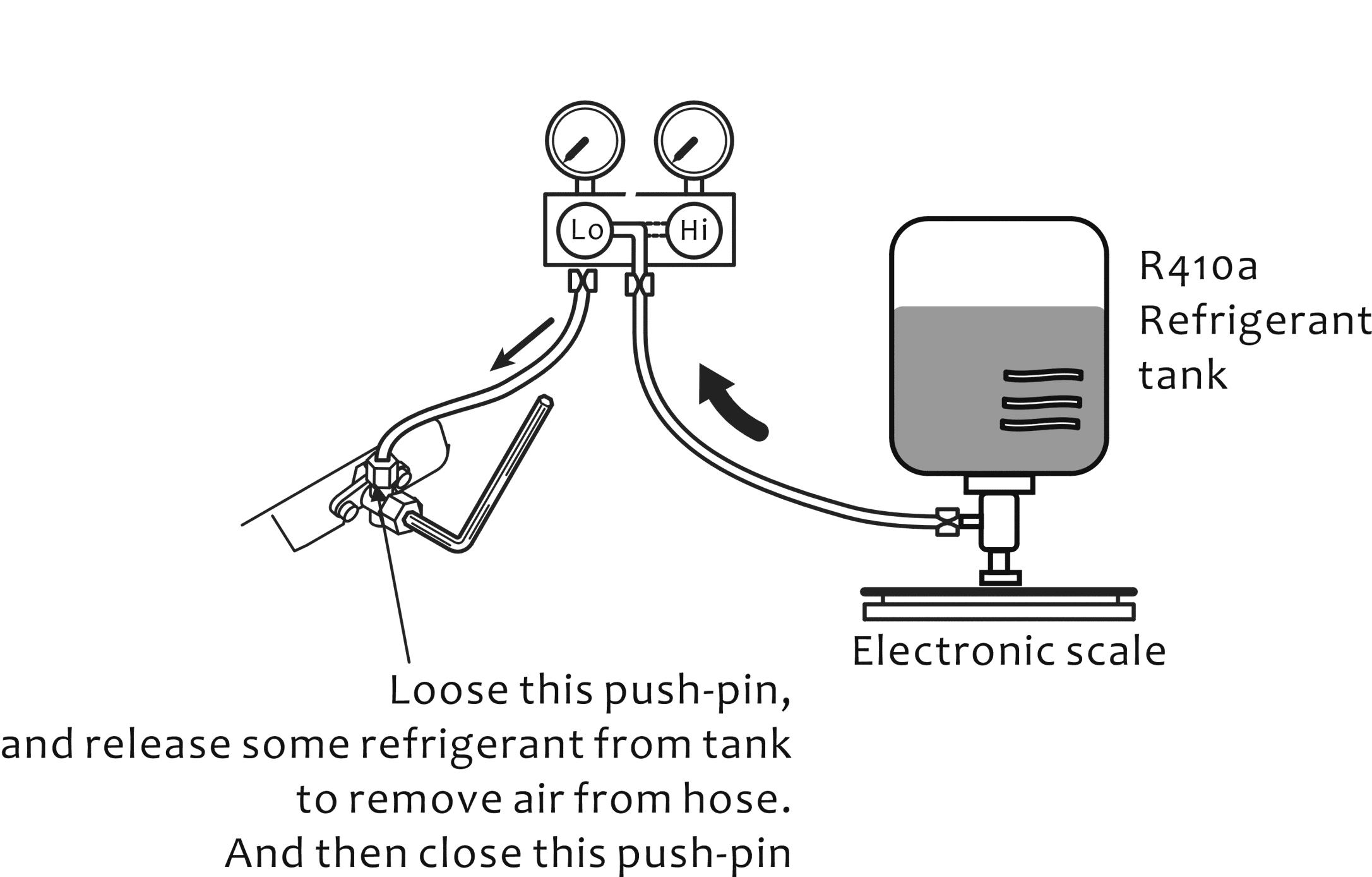
Openthechargevalvebyhexwrench,fillrefrigerantintoheatpump.Andclosethechargevalve whenfillenoughrefrigerantintoheatpump.
In winter ( below 0°C ), when the unit is no longer needed, please drain out all the water inside the heat pump.
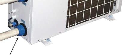
Screwthewaterinletconnectorawaytodrain waterawayfromheatpump.
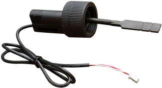
One water flow switch install on water outlet to ensure adequate water flow on heat exchanger before compressor start. It acts if partial block, or less water flow. After water pump run 30s, water-flow-switch continue 5s OPEN signal, then unit stop.
Controller displa PL error code. This error is recoverable.
When unit STANDBY, PCB check water sensor Ti, ambient air sensor Ta: *When2°C<Ti≤4°C,Ta≤2°C,thenenter1st antifreezemethod,waterpumpswitchON. *WhenTi<2°C,Ta≤2°C,thenenter2nd antifreezemethod,unitrunatHEATINGmode. IfTi≥5°CorTa≥3°C>4’c,thenprotectioncancel.
ControllerdisplayPCduringanti-freezeprotection.
Compressor Over-Heat Protection: Compressor discharge sensor : Tc Tc ≥ 105°C ( parameter P8 ), then unit stop. When Tc < 90°C, unit continue running. If 3 times error within 30 minutes, unit stop, then enter protection. This error unrecoverable, cancel by power OFF.
Communication:
PCB connect to controller, but controller can not receive signal from PCB 2 minutes consecutively, then enter protection.
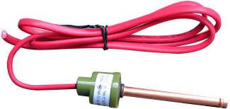
High Pressure Protection:
After compressor run 15s, high-pressure-switch give OPEN signal 5s, unit stop. If 3 times error within 30 minutes, unit stop, then enter protection. This error unrecoverable, cancel by power OFF.
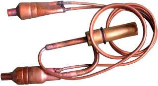
Low Pressure Protection:
After compressor run 5 minutes, low-pressure-switch give OPEN signal 10s, unit stop. If 3 times error within 30 minutes, unit stop, then enter protection. This error unrecoverable, cancel by power OFF.
Note:

This diagram is correct at the time of publication, manufacturing changes could lead to modifications. Always refer to the diagram supplied with the heat pump