3.4Initialoperation
Note:Inordertoheatthewaterinthepool(orhottub),thewaterpumpmustbe runningtocausethewatertocirculatethroughtheheatpump.Theheatpumpwillnot startupifthewaterisnotcirculating.
Afterallconnectionshavebeenmadeandchecked,carryoutthefollowingprocedure:
1SwitchonthewaterpumpCheckforleaksandverifythatwaterisflowingfromandtothe pool.
2ConnectpowertotheheatpumpandpresstheOn/Offbuttonontheelectroniccontrol panel.Theunitwillstartupafterthetimedelayexpires(seebelow).
3Afterafewminutes,checkwhethertheairblowingoutoftheunitiscooler
4.Whenyouturnoffthewaterpump,theunitshouldalsoturnoffautomatically,ifnotadjust theflowswitch
5.Allowtheheatpumpandthewaterpumptorun24hoursadayuntilthedesiredwater temperatureisreachedTheheatpumpwillstoprunningatthispointAfterthis,itwill restartautomatically(aslongasthewaterpumpisrunning)wheneverthepoolwater temperaturedrops1degreebelowthesettemperature
Dependingontheinitialtemperatureofthewaterinthepoolandtheairtemperature,itmay takemanyhoursorevenmorethanonedaytoheatthewatertothedesiredtemperature.A goodpoolcovercandramaticallyreducetherequiredlengthoftime
WaterFlowSwitch:
Itisequippedwithaflowswitchtopreventtheheatpumpofrunningwithinadequatewater flowrate.Itwillturnonwhenthepoolpumprunsandshutsoffwhenthepumpshutsoff.Ifthe poolwaterlevelismorethan1maboveorbelowtheheatpump’sautomaticadjustmentknob, yourdealermayneedtoadjustitsinitialstartup.
Timedelay-Theheatpumphasabuilt-in3-minutestart-updelaytoprotectthecircuitry andavoidexcessivecontactwearTheunitwillrestartautomaticallyafterthistimedelay expires.Evenabriefpowerinterruptionwilltriggerthistimedelayandpreventtheunitfrom restartingimmediatelyAdditionalpowerinterruptionsduringthisdelayperioddonotaffect the3-minutedurationofthedelay.
3.5Condensation
Theairdrawnintotheheatpumpisstronglycooledbytheoperationoftheheatpumpfor heatingthepoolwater,whichmaycausecondensationonthefinsoftheevaporator.The amountofcondensationmaybeasmuchasseverallitersperhourathighrelativehumidity Thisissometimesmistakenlyregardedasawaterleak.
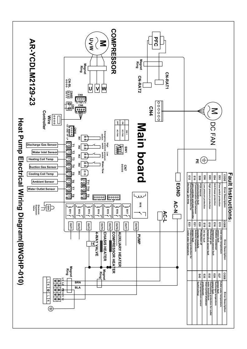
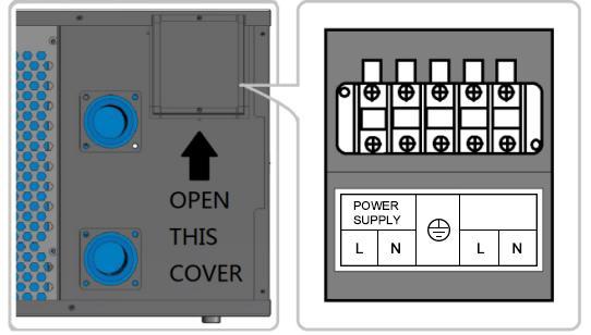
4.ElectricalWiring
NOTE:
(1)Theaboveelectricalwiringdiagramsareonlyforyourreference,pleasesubjecttheheat pumptothepostedwiringdiagram
(2)Theheatpumpmustbeearthedwell.Earthingtheunitisstillrequiredtoprotectyou againstshortcircuitsinsidetheunit
Disconnect:Adisconnector(circuitbreaker,fusedorun-fusedswitch)shouldbelocated withinsightofandeasilyaccessiblefromtheunitThisiscommonpracticeoncommercial andresidentialheatpumps.Itpreventsremotely-energizingunattendedequipmentand permitsturningoffpowertotheunitwhiletheunitisbeingserviced
5.Controller’sOperations
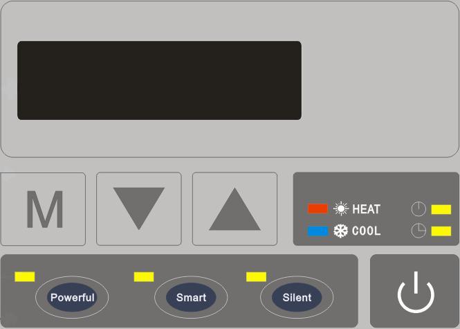
LEDDisplayController
5.1Overview
◎Thecontrollerisspeciallydesignedfortheheatpump,withfeaturesasbelow:
Heatingandcoolingmode;
Couldshowandchangetherunningandsettingparametersofthesystem,easy forusertoinstallandtest;
Withautomaticprotectionandfaultwarningfunction;
Withstrongsystemprotectionfunction,likecompressordelayprotection,high pressure,lowpressure,sensorprotection,waterflowdetect,andetc;
Thecommunicationdistancebetweentheheatpumpunitandwirecontroller shouldbelessthan100metersThecommunicationportisRS485;
Stronganti-interference,stableperformance.
5.2BasicModelofSystemControlChart
◎SystemChart
◎ControlPrinciple
Theheatpumprunsaccordingtothewirecontroller’sorder
Thewirecontrollercouldchangetherunningparametersandsendtherunning parameterstotheheatpump
Theheatpumpcoulddetecttherunningconditionandsendtheinformationorfault tothewirecontroller
HeatPump
WireController
◎BasicIcons
1.Whenit’sunderheatingmode, turnson
2Whenit’sundercoolingmode, turnson
3.Whenit’sunderdefrostingmode, turnsonandtwinkles
Whenit’sunderoffstatus,thedisplayshowsthecurrenttime
◎KeyOperatingInstruction
1)""KeyOn/Off
Whenit’sinotherinterface,pressthisbuttonshortly,itwillgobacktothemain interface.


Inthemaininterface,pressthiskeytoturnon/off
Inthemaininterface,pressthiskeyfor5secondstosetthetimer,whenhouron nixietubeflashes,youcansethourof"Timeron",thecorrespondingiconof"Timer on"flashes,press","tosethour.Whenfinishingsetting,presskey"" shortlytogotosetminuteof"Timeron",press","tosetminute.Whenfinish setting,presskey"Mode"togotosethourof"Timeroff",thecorrespondingiconof "Timeroff"flashes,press","tosethour.Aftersettingfinished,presskey"" shortlytogotosetminuteof"Timeroff",press","tosetminute.Aftersetting, presskey""andreturntothemaininterface,iftherelativelightison,itmeans thatthecorrespondingtimerissetsuccessfully


TimerCancel
Whenthetimeon"Timeron"and"Timeroff"issame,timeriscanceled.
5.3WireController
Attheinterfaceofsetting"Timeron"or"Timeroff",presskey""for 5seconds,"Timeron"or"Timeroff"canbecanceledindividually
Whentherelativelightisoff,itmeansthistimeriscanceled.
2)""KeyMode
Whentheheatpumpison,pressthiskeyshortly,youcanshiftdifferentmodes: heatingmode,coolingmode(Whentheheatpumpispoweredbythespa,the coolingfunctionwillonlybeavailablewhentheactualwatertemperatureislower thansettemperatureonthespacontroller).
Whentheheatpumpisoff,pressthiskeyshortlytosetthetime,4nixietubesare twinkling,atthistime,presskey""shortlytosetthehour,presskey","to setthehourWhenfinishing,presskey""shortlyagaintosettheminute
Whenfinishing,presskey""toreturntothemaininterface
3)""KeyPlus
Whentheheatpumpison,inthemaininterface,pressthiskeytoincreasethe settingtemperature
Whenit’sinmanualfrequencymode,inthehomepage,pressthiskeytoincrease thesettingfrequency

4)""KeyMinus
Whentheheatpumpison,inthemaininterface,pressthiskeytodecreasethe settingtemperature.
Whenit’sinmanualfrequencymode,inthehomepage,pressthiskeytodecrease thesettingfrequency.
5)""Key"POWERFUL"
Whentheheatpumpison,pressthiskeyshortlytogointopowerfulmode.
6)""Key"SMART"

Whentheheatpumpison,pressthiskeyshortlytogointosmartmode
Underoffstatus,pressthiskeyfor5secondstochangethetemperatureunit between℃and℉
7)""Key"SILENT"
Whentheheatpumpison,pressthiskeytogointosilentmode

Presskey""for5seconds,andenterintotheunitstatusparameterinquiry, presskey","toviewtheparameters,presskey""toexitparameter
8)StartingElectricHeaterManually
Presskeys""+""atthesametimefor5secondstoturnon/offthe electricheatermanually
9)EnforcedDefrosting
Whentheconditionsofenteringenforceddefrostingaremet,press""and""at thesametimefor5seconds,thenitenterintoenforceddefrostingmode.
Whenenteringintodefrosting,heatingmodeicon" "appears.When exitingfromdefrosting,modeiconrecovertonormaldisplay
10)RecovertoFactoryDefault
Bybuttonoperation:presskeys""+""atthesametimefor5seconds andenterintouserparametersmode,thecurrentparameterisreturntemperature Thenpresskeys""+""atthesametimefor5secondsandwired controllerrecoverstofactorydefault.Atthistime,buzzerwillalarmtwice continuously,andallparametersrecovertofactorydefault
query InquiryCode Descriptions DisplayRange 01 Inletwatertemp -20~99℃ 02 Outletwatertemp -20~99℃ 03 Ambienttemp -20~99℃ 04 Dischargetemp 0~125℃ 05 Suctiontemp -20~99℃ 06 Outercoiltemp -20~99℃ 07 Innercoiltemp -20~99℃ 08 MainEEVsteps 09 AssistantEEVsteps / 10(A) Compressorcurrent 11(B) Radiatortemp 12(C) DCbusvoltage 13(D) Compressoractualrotatespeed 14(E)DCfanmotoractualrotatespeed
11)Systemparametersetting
Press""+""for5secondstoenterthepasswordinterfaceforsettingthe parameters.Thenpress""or""toenterthepassword.Press""to changethedigitofthepassword.Afterfinishingthelastdigit,press""to confirmthepassword
6.SystemParameters:
Parameter Code ParameterName SetRange FactorySetting 1 ReturnDifferencefor TargetWaterTemp 1~18℃(2~36℉) 1℃(2℉) 2 SetTempinCoolingMode 8℃~35℃(46~95℉) 27℃(81℉) 3 SetTempinHeatingMode 5℃~40℃(41~104℉)40℃(104℉) 4 CompensationValueofInletWaterTemp-5℃~15℃(-9~30℉) 0℃(0℉) 5 DefrostingCycle 20MIN~90MIN 45MIN 6 DefrostingStartTemp -9℃-1℃(1630℉) -3℃(27℉) 7 DefrostingTime 5MIN~20MIN 8MIN 8 TemptoQuitDefrosting 1℃~40℃(33~104℉)20℃(68℉) 9 Differencebetween AmbientTempandCoilTemp toStartDefrosting 0℃~15℃(0~30℉) 5℃(10℉) 10 AmbientTemp.toStart Defrosting 0℃~20℃(32~68℉) 17℃(63℉) 11 ElectronicExpansionValve's WorkingCycle 20S~90S 30S 12 OverheatDegreeinSmart/ PowerfulMode -5℃~10℃(-9~20℉) Dependson ActualModel d(13) ExhaustGasTempof ElectronicExpansionValve 70℃~125℃(158~257℉)95℃(203℉) 14 ElectronicExpansionValve's StepsduringDefrosting (SetValue*10=ActualSteps) 2~45 Dependson ActualModel 15 ElectronicExpansionValve's MinSteps(SetValue*10=ActualSteps) 5~15 10 16 ElectronicExpansionValve's WorkingMode 0Manual/1Auto 1 17 ManualStepsof ElectronicExpansionValve (SetValue*10=ActualSteps) 2~45 35
Note:Intheabovetable,theactualvalueoftheelectronicexpansionvalveand theairspeedis10timesoftheparameterdisplayedvalue.Forexample,whenthe P20defrostexpansionvalveopeningdegreeshows30,theactualvalueatthistimeis 300steps;whenP30fanmanualrotationspeedshows80,theactualvalueatthis timeis800.Whenthevalueismorethan100,Arepresentsfor10,Brepresentsfor11, Crepresentsfor12,andDrepresentsfor13.
7.Troubleshooting
7.1Systemprotection/errorindication
18 OverheatDegreeinCooling Mode -5℃~10℃(-9~20℉) Dependson ActualModel 19 Reserved / / 20 ElectronicExpansionValve's WorkingModeWhenCooling 0=WaterTemperature 1=Supercooling 1 21 WaterPump'sWorkingMode WhenTargetTemperatureReached 1=NonStop/2=Stop 3=Intermittent 3 22 Fan'sWorkingMode 0=Auto/1=Manual 0 23 Fan'sManualControlSpeed (SetValue*10=ActualSpeed) 0-99 (SetValue*10=Actual Speed) 80 (Set Value*10=Actual Speed) 24 AmbientTemptoStart AuxiliaryElectricHeater -20℃~20℃(-4~68℉)-20℃(-4℉) 25 AuxiliaryHeating FunctioninDefrosting Mode 0Non/1Yes 1
ErrorcodeErrordescriptions Solutions Er03 waterflowfailure Checkwaterflow/switch Er04 winteranti-freezing Waterpumpwillrunautomatically forfirstgradeantifreeze Er05 highpressurefailure 1Dischargeredundant refrigerantfromheatpumpgas system 2Cleanthewaterexchangeror waterfifter Er06 lowpressurefailure 1.Checkifthereisanygas leakage,re-filltherefrigerant 2.Replacethefilterorcapillary Er09 communicationfailurebetweenDisplay andPCB 1Checkifthecommunication connectionwirebetweendisplay andPCBisdisconnectedorhas poorcontactChangethewireor
Er10 communicationfailureoffrequency conversionmodule(alarmwhen communicationbetweendisplayand PCBaredisconnected)
menditifyes
2CheckifPCBordisplayis damagedChangethe correspondingpartifyes
ChangePCB
Er12 excessiveexhausttempprotection1.Replacethecompressor dischargetemperaturesensor
2.Reconnectorcleancompressor dischargetemperaturesensorand wrapitwithinsulationtape
ReplacethecontrollerorPCBoard
Er15
Waterinlettemperaturefailure
Checkorchangethesensor
Er16 externalcoiltemperaturefailure Checkorchangethesensor
Er18 exhausttemperaturefailure
Er19 DCFanmotorfailure
Checkorchangethesensor
1CheckifDCfanmotoris
damagedChangeitifdamaged
2CheckifDCfanmotoroutput
portonPCBhasoutputChange PCBifnooutput
Er20 Abnormalprotectionoffrequency conversionmodule
Er21 ambienttemperaturefailure
Er23 toolowcoolingoutletwatertemp protection
Er27 wateroutlettemperaturefailure
Er29 Returngastemperaturefailure
Er32 Toohighheatingoutletwater temperatureprotection
Er35 Compressorcurrentprotection
Solveitaccordingtothesubsidiary errorcodesinthefollowingtable.
Checkorchangethesensor
Checkwhetherthewaterflowor watersystemisjammedornot
Checkorchangethesensor
Checkorchangethesensor
Checkwhetherthewaterflowor watersystemisjammedornot
1Checkiftheincomingvoltage supplyistoolow,ifso,repair
2Checkifthecompressoris overloadedandrepair
3Checkwhetherthethermalrelay isdamaged,ifso,replace
Er42 internalcoiltemperaturefailure
Checkorchangethesensor
◎E20faultwilldisplaythefollowingerrorcodesatthesametime,theerrorcodeswill switchevery3secondsAmongthem,errorcodes1-128aredisplayinpriority
Whenerrorcodes1-128don’tappear,thenerrorcodes257-384canshow. Iftwoormoreerrorcodesappearatthesametime,thendisplayerrorcodes accumulation.Forexample,16and32occuratthesametime,display48.
Error Code Name Descriptions Solutions 1 IPMOver-currentIPMModuleproblem Replaceinverter module 2 compressor synchronous abnormal Compressorfailure Replacecompressor 4 reserved -- -8 compressor outputphase absent Compressorwiring disconnectedorpoorcontact Checkingcompressor inputcircuit 16 DCbuslow voltage Inputtoolowvoltage,PFC modulefailure, Inspecttheinput voltage,replace module 32 DCbushigh voltage Inputvoltagetoohigh,PFC Modulefailure Replaceinverter module 64 Radiatorover temperature Mainunitfanmotorfailure,air ductblockage Inspectfanmotor,air duct 128Radiator temperatureerror Radiatorsensorshortcircuit oropencircuitfault Replaceinverter module 257communication failure Invertermoduledoesn’t receiveorderfrommain controller Inspectionthe communication wiring=betweenmain controllerandinverter module 258ACInputphase absent Inputphaseabsent(Three phasemoduleiseffective) Inspectioninputcircuit 260ACInput over-current Inputthreephaseimbalance (threephasemoduleis effective) Inspectioninputthree phasephasevoltage 264ACInputlow voltage Inputlowvoltage Inspectinputvoltage 272CompressorHigh pressurefailure Compressorhighpressure failure(reserved) 288IPMtoohigh temperature Mainunitfanmotorfailure,air ductblocked Inspectfanmotorand airduct 320Compressorpeak currenttoohigh Compressorlinecurrenttoo high,thedriverprogram doesn’tmatchwith compressor Replaceinverter module 384PFCmodule over-temperature PFCModuletoohigh temperature
MalfunctionsObservation
LEDwirecontroller shows nodisplay
LEDwirecontroller displaystheactualtime
Reasons
Nopowersupply
Solutions
Checkwhethercableandcircuit breakerareconnected
Heatpumpunderstandby status Startupheatpumptorun
Heatpumpis notrunning
Water temperatureis coolingwhen heatpumpruns underheating mode
LEDwirecontroller displaystheactual watertemperature
1Watertemperatureis reachingsetvalue,heat pumpunderconstant temperaturestatus
2Heatpumpjuststartsto run
3Underdefrosting
1.Verifywatertemperaturesetting 2Startupheatpumpafterafew minutes
3LEDwirecontrollershoulddisplay "Defrosting"
LEDwirecontroller displaysactualwater temperatureandnoerror codedisplays
1Chosethewrongmode
2Figuresshowdefects
3Controllerdefect
1Adjustthemode
2ReplacethedefectLEDwire controller,andthencheckthestatus afterchangingtherunningmode, verifyingthewaterinletandoutlet temperature
3Replaceorrepairtheheatpump
Shortrunning
LEDdisplaysactualwater temperature,noerror codedisplays
1FanNOTrunning
2Notenoughair ventilation
3Notenoughrefrigerant
1.Checkthecableconnections betweenthemotorandfan,if necessary,theyshouldbereplaced
2Checkthelocationoftheheat pump,andeliminateallobstaclesto assureagoodairventilation
3Replaceorrepairtheheatpump
2Checkthetitaniumheatexchanger carefullyifitshowsanydefects
1Checkthelocationofheatpump, andeliminateallobstaclestoassure agoodairventilation
2.Replaceorrepairtheheatpump
7.2OtherMalfunctionsandSolutions(NodisplayonLEDwirecontroller)
waterstains Waterstainsonheat pumpunit 1Concreting 2.Waterleakage
1Noaction
Toomuchice onevaporator Toomuchiceon evaporator
8.Maintenance
(1)Youshouldcheckthewatersupplysystemregularlytoavoidtheairenteringthesystem andoccurrenceoflowwaterflow,becauseitwouldreducetheperformanceandreliabilityof theheatpump
(2)Cleanyourpoolsandfiltrationsystemregularlytoavoidthedamageoftheunitasaresult ofadirtyorcloggedfilter
(3)Youshoulddischargethewaterfromthebottomofthewaterpumpiftheheatpumpwill stoprunningforalongtime(speciallyduringthewinterseason).
(4)Onanyothermoment,youshouldcheckiftheunithasenoughwaterbeforetheunit startstorunagain
(5)Aftertheunitisconditionedforthewinterseason,itispreferredtocovertheheatpump withthespecialwinterheatpumpcover.
(6)Whentheunitisrunning,thereisalwaysalittlewaterdischargeundertheunit.