


Challenge
Crossing the street without a signal that indicates it is safe can be dangerous, and our goal is to help people to cross safely. In this situation, the street to be crossed is 30 feet wide and has two lanes of traffic. The speed limit is 35 mph which means cars are moving at approximately 51.3 feet per second. When the crosswalk signal is pushed, you will need to allow sufficient time for approaching cars to stop and for people to safely cross the street.
The crosswalk signal should have a steady green light when it is safe to cross, a steady right light when it is not safe to cross, and a blinking red light for three seconds after people have safely crossed. The blinking phase alerts drivers that pedestrians may still be finishing their crossing.
Specifications (what does the design have to do)
1) Allow time for cars to stop when the “Walk” button is pushed.
2) Allow time for a person to safely cross the street.
3) After the “Walk” signal turns off, display a blinking red ”Don’t Walk” signal for 3 seconds. Follow the flashing signal with a steady red “Don’t Walk” signal to indicate it is no longer safe to begin crossing.
Constraints (things that limit your solution)
These relate to the materials available and the class time available for the challenge.
Materials
Cardboard strips
Tape
Hummingbird LED lights
Hummingbird light sensor
Glue gun
Assessment Rubric: Design and Engineering
Criteria 1 2 3
Alternative Designs
Crossing Time Calculations
Sensor Operation Code
Describes one design idea. No rationale or consideration of alternatives provided.
Provides incomplete or unclear explanation of crossing time. Lacks calculation steps.
Uploaded code for LED only. No explanation or integration with sensor.
Final Design and Documentation
Includes only a photo and basic code. No explanation
Describes two design options and explains the choice using one reason (e.g., easier to build or test).
Accurately calculates vehicle slow-down and pedestrian crossing time. Explanation includes steps.
Uploaded code integrates LED and light sensors. No explanation of logic.
Includes photo, code, and a short explanation of how the system works.
Describes three or more design options and explains final choice using multiple factors (e.g., efficiency, accuracy, feasibility).
Accurately calculates vehicle and pedestrian times. Answers all related questions with complete, step-by-step explanations and units.
Uploaded code uses LED and light sensors with clear explanation or comments showing how sensor data controls LED behavior.
Includes annotated code, labeled photo, and detailed explanation of function and changes made during development
Testing and Evaluation
Little or no testing. No discussion of whether design met goals.
Reflection on Learning Mentions one general takeaway (e.g., 'I learned about timing.').
Performs basic testing and explains one result (e.g., LED turned on when it should)
Identifies two things learned with examples (e.g., using sensors or debugging code).
Conducts structured testing for multiple cases. Explains whether design met goals and what was revised or could be improved.
Provides a thoughtful reflection on at least two learnings, including challenges faced and strategies used to solve them.
Knowledge and Skill Builders (KSBs)

KSB 1 Preliminary Design
Think about crossing the street where there is a crosswalk. There are different colored lights that indicate “Walk” and “Don’t Walk.” Typically, the “Don’t Walk” light is on until you push the button. When you do so, the light does not immediately turn to “Walk” because there needs to be time for cars to slow down and come to a complete stop.
Below are pictures from one crosswalk. Notice that pictures are used, as not everyone can read English. Some crosswalks have words, others have symbols. You will choose your preferred approach—word, symbols, or both when creating your preliminary design.
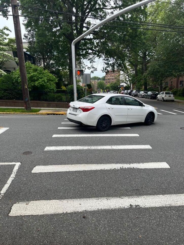
Figure 1. The “Don’t Walk” signal is on, showing a red hand, while a car is turning, indicating that cars are allowed to go through the intersection.
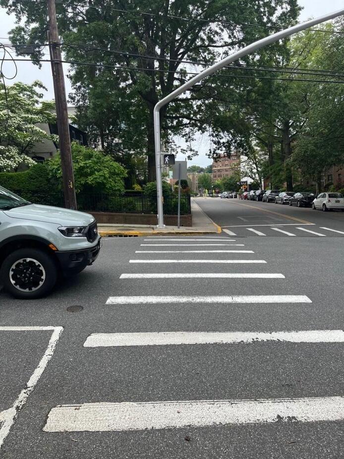
Figure 2. The “Walk” signal is on, the car is stopped, and people can safely cross the street.
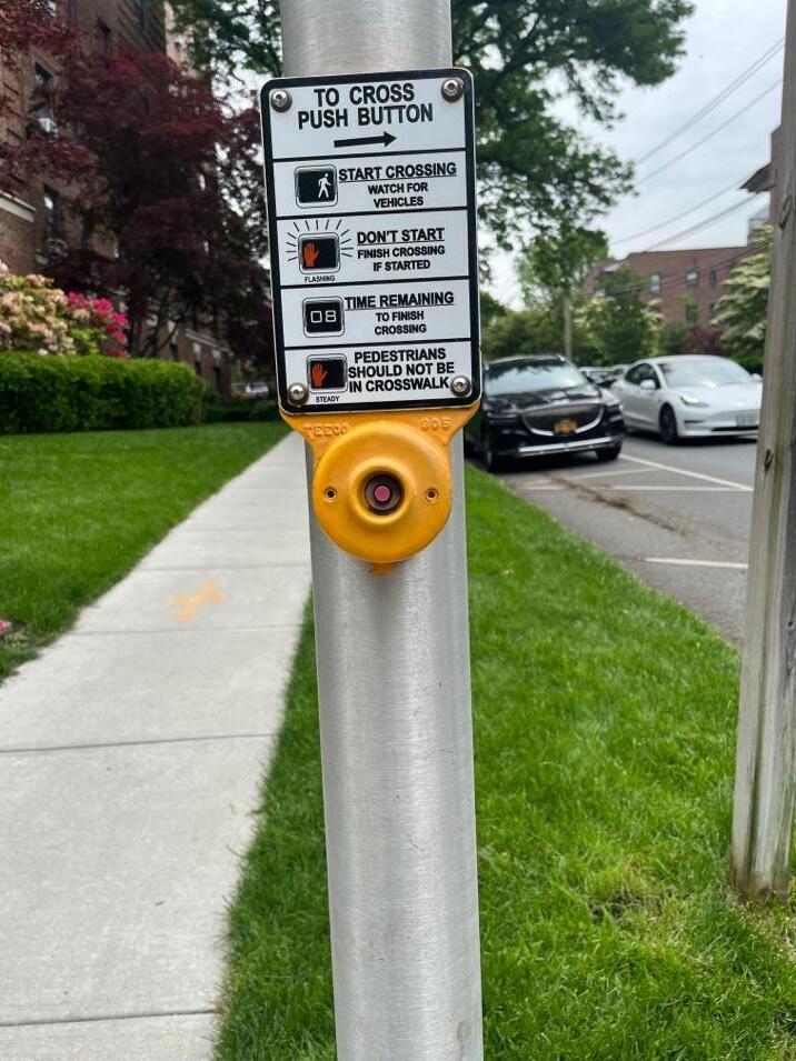
Figure 3. Crosswalk push button with information about the signal.
Let’s see what your preliminary design should include: signal lights indicating “Walk” and “Don’t Walk.” and a button to push to activate the crosswalk signal system. In later KSBs you will learn how to create the lights, write the code to control how the system operates; and to revise your design as needed with the new knowledge you have. Here is an example of a simple crosswalk system.
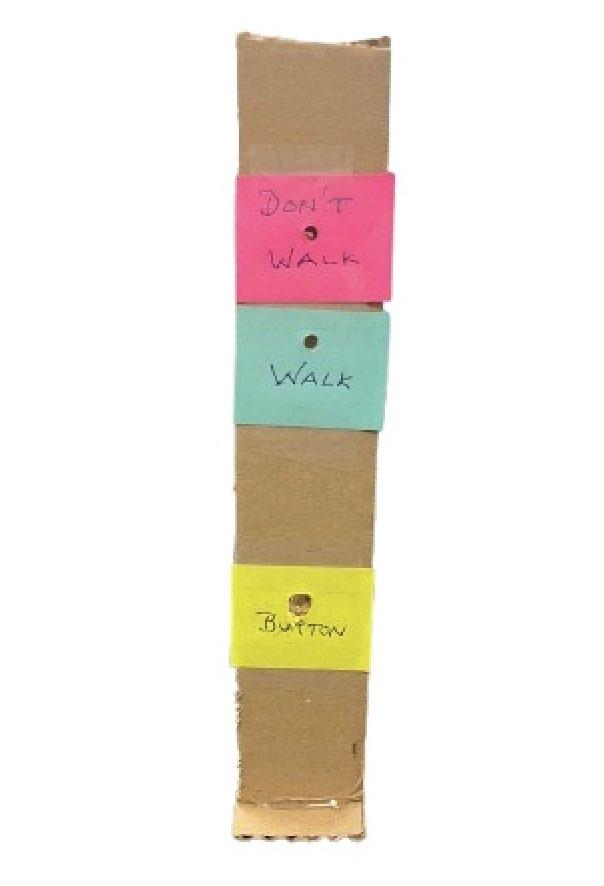
Figure 4. A basic crosswalk system with a button to push and “Walk” and “Don’t Walk” light indicators.
KSB 2 Crossing Time
Traffic designers assume that people move at 4 feet per second when walking in a crosswalk.
Cars traveling at 35 mph are moving at 51.3 feet/second. A driver’s undistracted reaction time is about three-quarters of a second (.75 seconds). When the walk button is pushed, there needs to be a built-in delay so that traffic approaching the intersection has enough time to stop or safely pass through the crosswalk. It takes time for people to react, and also takes time for the vehicle to safely stop. You may want to discuss distracted driving. When a driver is texting, talking on the phone, or even just engaged in conversation with passengers, their reaction time increases. That means the car travels even farther before the driver notices the signal change and starts to brake making it more dangerous for pedestrians.
Standards indicate that vehicles slow down at a rate of 15 feet/second once the brakes are applied.
Now it is time to determine the time delay from when the button is pushed for the “Walk” light to go on. Show your calculations.
It takes 0.75 seconds for a driver to react to the signal change to stop.
Once braking begins, the car slows down at a rate of 15 feet per second. Ac car traveling at 51.3 feet/second (equivalent to 35 mph) takes (51.3 ft/s)/(15 ft/s) = 3.4 seconds to stop. Thus, including the reaction time (.75 seconds), the total time for the light to change from “Don’t Walk” to “Walk” is 4.15 seconds. This is the minimal value; students may want to increase this slightly because of distracted driving, or driving at higher speeds.
Crossing the 30-foot street at a pace of 4 ft/s takes (30 ft)/4 ft/s) = 7.5 seconds. Students may want this to be longer if this is a crosswalk where elderly pedestrians, young children, or people pushing strollers or using mobility aids cross.
Finally, there are 3 seconds of blinking red, “Don’t Walk,” occurring.
How long should the light indicate “Walk”? Show your calculations.
When do you want the blinking “Don’t Walk” light to start and end?
When should the “Don’t Walk” light be a steady red light?
KSB 3 How Sensors Operate

Here is a link to illustrate how different sensors and servos operate in Hummingbird Snap!
This link is for the light sensor. In this project, we’re replacing the traditional crosswalk push button with a light sensor. When the sensor is covered by a finger and reads a value lower than 10, it’s used to trigger the crosswalk system just like pressing a button would. https://learn.birdbraintechnologies.com/hummingbirdbit/snap/program/13-1
Other sensors we will be using are the LED sensors. There are three single-color LED sensors and one tri-color LED sensor.
https://learn.birdbraintechnologies.com/hummingbirdbit/snap/program/6-1
Follow the directions for programming the light sensor. Create code so that when the sensor is darkened by your finger, an LED will light up. Take a picture of your code and paste it here.
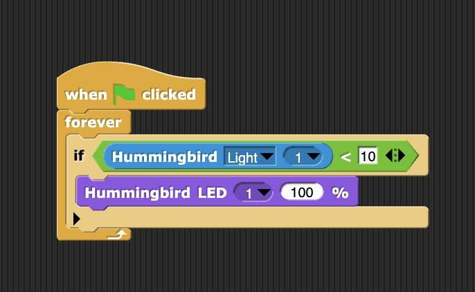
Figure 5. Covering the light sensor causes LED 1 to illuminate at 100% brightness.
KSB 4 Thinking Like a Computer

Computers are controlled by code; in this case, the computer program you create will control the lights to help a person safely cross the street.
Think about what you want to happen step by step. This is how the computer reads the directions you give it through the code you write. Before you begin programming, go back to the challenge statement and review what is supposed to happen.
Indicate the sequence of events.
1. The red, “Don’t Walk” light is on.
2. The button is pushed to request the Green “Walk” light to turn on.
3. There is a time delay for traffic to stop.
4. The green “Walk” light turns on for the required time to cross the street.
5. The green light goes off and the Red light blinks.
Alternative Crosswalk Light System Designs
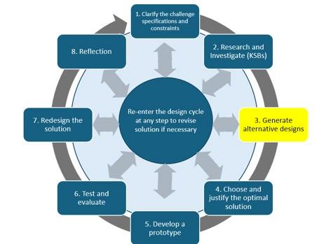
What do you want your crosswalk light system to look like? Where are you going to place the “Walk” and “Don’t Walk” indicators? Make a few sketches of what alternatives might be. You will be using the light sensor as the push button and LEDs for “Walk” and “Don’t Walk.” You can think about graphic indicators for “Walk” and “Don’t Walk.” You will be using cardboard to build your system.

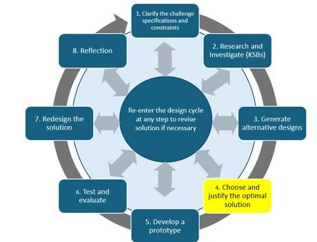
Which alternative design did you like best? Why do you think this is the optimal design? Please explain.
Crosswalk System—Part 2—Crosswalk Code
Now you need to put everything together and create a Crosswalk Code that will allow a person to safely cross the street. Often times as you write and test the code, you need to make changes. Take a picture of your initial code solution and paste here.
Now take a picture of your final code solution that works and paste that here.
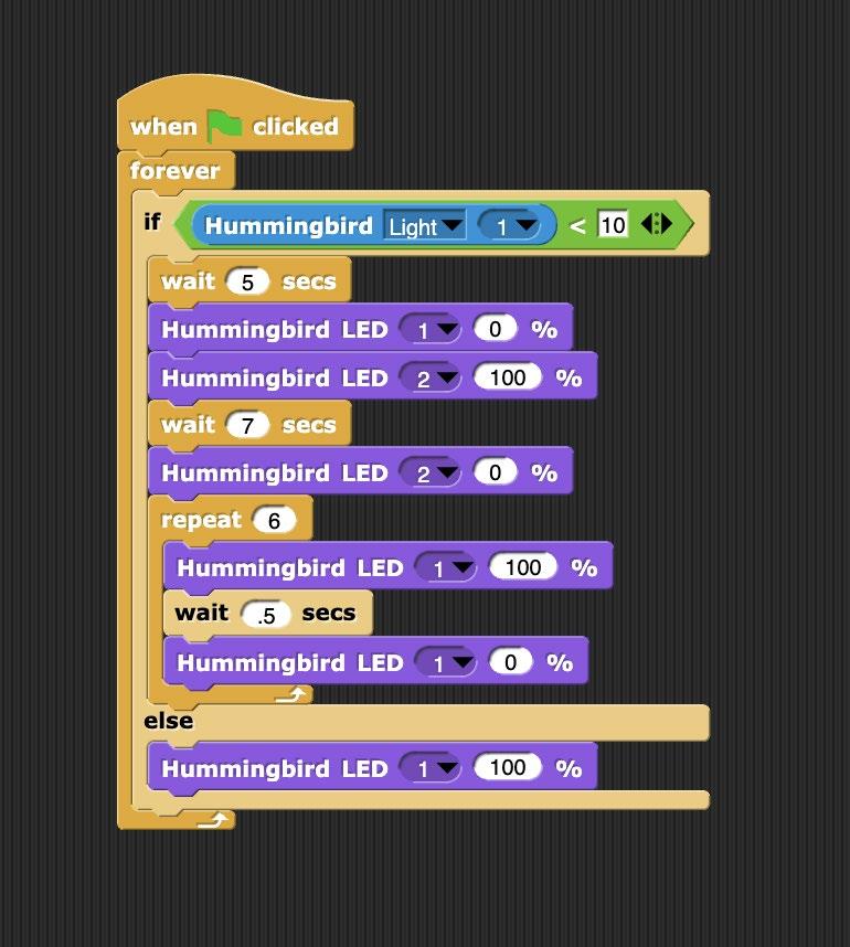
In this situation, covering the light sensor with your finger simulates pressing a crosswalk button. That causes the sequence of controlled by your code. actions beneath it. First, nothing happens for 5 seconds, which corresponds to the time it takes the driver to react and a car to stop, which was 4.15 seconds, rounded up to 5 seconds. LED 1 is the red “Don’t Walk” LED which is on. Then after 5 seconds, LED 1 goes off (0%) and LED 2, the green “Walk” signal is on. It stays is on for 7.5 seconds, the time necessary to cross the street. When the 7.5 seconds have passed, the green “Walk” light turns off, and the Red “Don’t Walk” light begins to blink. This blinking phase lasts for 3 seconds and serves as a warning for pedestrians who are already in the crosswalk to finish crossing. The blinking is controlled by a repeat loop that turns the red light on and off every 0.5 seconds, completing six cycles in total.
Finally, the red light returns to a steady on state, indicating once again that it is not safe to cross. The system remains in this state (LED 1 is on at 100%) until the light sensor is covered again, which restarts the entire process.
Why did you change the code?
Develop Your Prototype
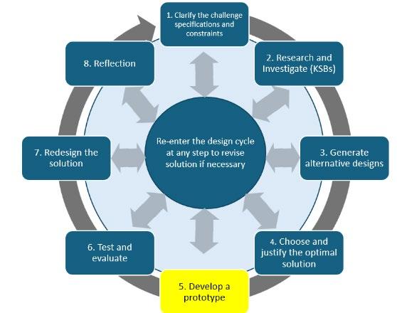
Now it’s time to build the crosswalk light system. This includes assembling all the necessary components: writing the code, setting up the Hummingbird controller, wiring the LEDs for the “Walk” and “Don’t Walk” signals, and connecting the light sensor, which functions as the push button.
. Take a picture of your final design and include it below.
Test and Evaluate
Did your solution work as intended to meet the design specifications? Briefly explain why it did or did not. How did you test the design?

You can include a photo of your final code and the cardboard crosswalk here.
Redesign Ideas
Reflection
Engineers always seek to make devices more efficient, to function better, and perform more effectively. What are your ideas as to how to improve your design?
What did you learn? You can think about coding, how crosswalks work, and issues to consider when designing a crosswalk. How have your own experiences influenced your design?
Alternative Designs
Describes one design idea. No rationale or consideration of alternatives provided.
Crossing Time Calculations Provides incomplete or unclear explanation of crossing time. Lacks calculation steps.
Sensor Operation Code
Uploaded code for LED only. No explanation or integration with sensor.
Final Design and Documentation
Testing and Evaluation
Reflection on Learning
Describes two design options and explains choice using one reason (e.g., easier to build or test).
Accurately calculates vehicle slow-down and pedestrian crossing time. Explanation includes steps.
Uploaded code integrates LED and light sensors. No explanation of logic.
Includes only a photo and basic code. No explanation. Includes photo, code, and a short explanation of how the system works.
Little or no testing. No discussion of whether design met goals.
Mentions one general takeaway (e.g., 'I learned about timing.').
Performs basic testing and explains one result (e.g., LED turned on when it should).
Identifies two things learned with examples (e.g., using sensors or debugging code).
Describes three or more design options and explains final choice using multiple factors (e.g., efficiency, accuracy, feasibility)
Accurately calculates vehicle and pedestrian times. Answers all related questions with complete, step-by-step explanations and units.
Uploaded code uses LED and light sensors with clear explanation or comments showing how sensor data controls LED behavior.
Includes annotated code, labeled photo, and detailed explanation of function and changes made during development.
Conducts structured testing for multiple cases. Explains whether design met goals and what was revised or could be improved.
Provides a thoughtful reflection on at least two learnings, including challenges faced and strategies used to solve them.
Extension Activity: Crosswalk activity with a traffic light. If you want to extend the activity, you could have students create the traffic light for cars, so the traffic light signals would correspond to the “Walk,” “Don’t Walk,” signals.
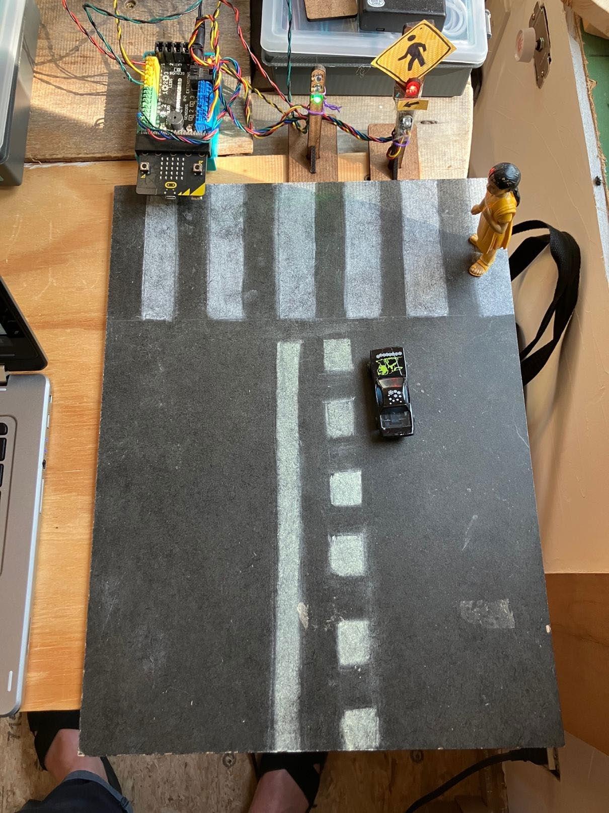
Figure 7. In this example, both a traffic light and a crosswalk light are included in the system. Incorporating both elements requires more complex coding, as the two systems must work together to manage both vehicle and pedestrian signals safely. Creating and studying an example like this can help students better visualize the real-world scenario and understand how traffic flow and pedestrian safety are coordinated.