49 minute read
ZE205E/ZE230E HYDRAULIC EXCAVATOR OPERATION MANUAL


Chapter Four: Safe operation and operating techniques of excavator
Chapter Four: Safe operation and operating techniques of excavator
4.1 Adjustment before operation
4.1.1 Adjustment of driver's seat
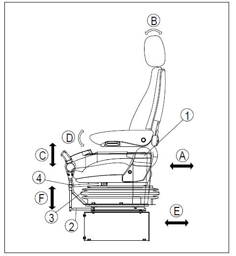
Adjust the seat as shown in Figure 4-1 so that the operator can operate the levers and switches freely and easily while sitting against the seat The methods for seat adjustment are as follows:: a) a) Adjust the seat forward or backward
Move the seat with the lever 4 to the desired position and then release the lever. Adjustable range: 110mm (10mm per class) b) b) Adjust the backrest c) Adjust the seat height d) Adjust the armrest angle e) Adjust the seat and lever forward and backward as a whole
Pull the handle ① up to set the backrest at the best position for easy operation and then release the handle.
1. While adjusting the inclination of the backrest, be careful not to interfere with the rear A/C cover plate and not to allow the armrest to touch the lever.
Lift the seat up to hear a "click" sound and the sit will be raised up by 30mm; continue to move it up to hear the second "click" sound and the sit will be lift up by another 30mm; further lift it up and the seat will be lowered to the lowest position. Maximum height adjustment: 60mm (each time 30mm).
The armrest can be lifted up for 100 °and be adjusted continuously for 40 °(10 °above the level and 30 °below the level).
Pull the handle ② up to adjust the seat to the desired location and release the handle. In this case, the driver's seat, left and right levers as well as safety locking lever will move together. Adjustable range for forward and backward adjustment: 160mm f) Adjust the seat suspension
Turn the knob ③ to make the suspension become flexible or fixed and make the weight displayed (kg) at the transparent part of the knob conforms to the weight of the operator. Adjustable range: 50-130kg. g) Adjust the headrest height
Lift or press the headrest to adjust it to the most appropriate height.
4.1.2 Adjustment of rearview mirror
The method for rearview mirror adjustment (shown in Figure 4-2) is as follows: a) Loosen the nut ① and bolt ② that fasten the mirror and adjust the position of the mirror to provide the best view for the blind area at the rear of the machine. b) Adjust the rearview mirror installation, so that the driver can see people at the rear left and right of the machine (or object with a height of 1m (39.3in) and a diameter of 300mm (11.8in)). c) Mount the rear-view mirror according to the mounting position and size shown as follows. The values provided below are the reference values for the field of view.
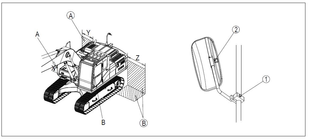
Mounting position X: 100mm (3.9 in)
Field of view Y (right): 1500mm (59.1in) d) Field of view Z (left): 1830mm (72in)
Mirror A: reflect the region (A) marked by the slash.
Mirror B: reflect the region (B) marked by the slash.
4.1.3 Seat belt (optional)
Warning
1. Before using the seat belts, check whether the mounting bracket and installation of the seat belts are in good condition. If any seat belt is worn or damaged, it should to be replaced.
2. Even if a safety belt appears to be in good condition, it has to be replaced once every three years. The manufacture date of a seat belt is shown on the back of it.
3. Do no distort the seat belt when fastening it.
The seat belt can wind up automatically, so length adjustment is unnecessary. The adjustment of the seat belt is shown in Figure 4-3 and the adjustment method is as follows: a) Fasten the seat belt b) Unfasten the seat belt

Hold the seat belt clip ② and pull the seat belt out from the winding device ①. Check whether the seat belt is twisted and then insert the tongue ③ into the buckle ④ firmly Then gently pull the seat belt to make sure that it is properly locked.
Press the button ⑤ on the buckle ④ and take the tongue ③ out from the buckle ④. The seat belt will wind up automatically and hold the seat belt clip ② so that the seat belt returns into the winding device slowly.
The seat belt of the machine is an optional part and you can order it from Zoomlion, or Zoomlion dealer according to your demands
4.2 Engine operation
4.2.1 Check before starting the engine
4.2.1.1 Basic checks
1. Before starting the engine, you should check the machine and the surrounding area to see if any bolt or nut is loose, if there is any oil, fuel or coolant leakage and if the working device and hydraulic system are in good condition. Besides, check whether any wire exposed to high temperature is loose and whether there is any clearance or dust accumulation.
2. Remove any combustible in the surrounding area of the battery, engine, muffler and other high-temperature engine components. Fuel or oil leak may make the machine catching a fire. Please check carefully; for any repair, please contact Zoomlion dealer.
Daily checks before starting the engine: a). Check whether there is any damage, wear or clearance in the working devices, cylinders, connecting rods and hoses. Check whether there are any cracks, excessive wear or clearance in the working devices, cylinders, connecting rods and hoses. If any abnormality is found, please have it repaired. b). Remove dust and dirt around the engine, battery and radiator. Check whether there is any dust and dirt accumulated around the engine or radiator. Also check whether there are any combustibles (leaves, twigs and grass, etc.) accumulated around the battery or high-temperature components such as engine muffler or turbocharger. All dirt and combustibles should be removed. c). Check whether there is any water or oil leakage around the engine. Check whether the engine has oil leakages and whether the cooling system has water leakages. If abnormality is found, repair soon. d). Check to make sure there is no oil leakage at the hydraulic units, hydraulic oil tank, hoses and joints. The check should be done to all of them without missing any one. Leakage is found should be repaired. e). Check the lower part of the machine (track, sprockets, idlers and guard) to see if there is any damage, wear, loose bolts or oil leakage at the rollers f). Check whether any handrail is damaged or any bolt is loose. Repair the damaged parts and tighten the loose bolts. g) Check whether any meter or monitor is damaged or any bolt is loose. Confirm that the instruments and monitors in the cab are in good condition. If any abnormality is found, the parts should be replaced and the dirt on the surface should be cleaned. h). Clean the rearview mirrors and check for damage. Confirm that the rearview mirrors are not damaged. Otherwise, they should be replaced with new ones. Clean the mirror face and adjust the angle so that the driver can see the rear view from the driver’s seat i). Check to see if the seat belts and buckle (if any) are in good condition,. If damaged, they should be replaced with new parts. j). Check whether the hook bucket (if equipped) is damaged. Check whether the hook, limiter and hook seat are damaged. If any damage is found, please contact Zoomlion or Zoomlion dealers for repair.
4.2.1.2 Check the coolant
1. Do not open the radiator cap unless necessary. Do not check the coolant in the reserve tank until the engine cools down.
2. When the engine is turned off, the coolant is hot and the internal pressure of the radiator is high. Under such condition, there will be danger of burns if you remove the radiator cap to drain the coolant. Therefore, you should wait until the cap cools down and then turn it cap slowly to release pressure.
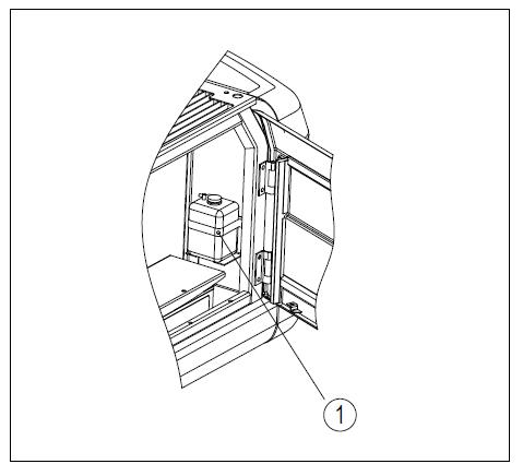
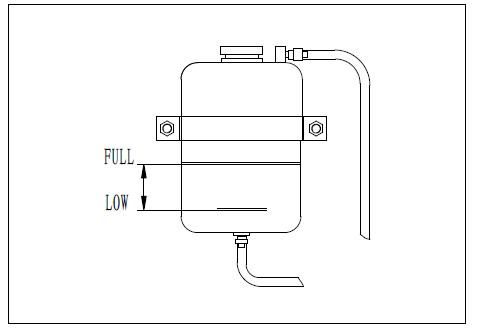
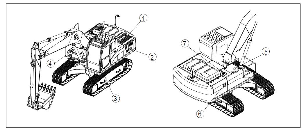
Checking steps: a). Open the left rear door of the machine to check the reserve water tank ① shown in Figure 4-4. b). Check whether the coolant level in the reserve water tank is between the LOW and FULL mark, as shown in Figure 4-5. If the coolant level is too low, add coolant to the FULL mark through the filling port c). Screw the cap on firmly when the coolant is added full. d). If the reserve water tank is empty, it maybe leak e) Repair immediately after the check. If there is no abnormality, check the coolant level in the radiator; if the level is too low, add coolant to the radiator and then add coolant to the reserve tank ①.
4.2.1.3 Check the engine oil
Warning
1. When the engine is shut down, the parts and oil are still hot, which may cause serious burns. Therefore, you should wait until the oil cools down before operation.
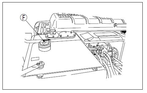
Checking steps: a). Open the engine cover on the machine. b). Pull the dipstick (F) out and wipe off the oil with a cloth. c). Insert the dipstick (F) fully into the oil filling port, and then pull the dipstick out d). The oil level should be between the H and L mark on the dipstick (F). If the oil level is below the L mark, you should add oil through the filling port (G), as shown in Figure 4-6. If the oil level is higher than the H mark, open the drain valve at the bottom of the engine sump (P) to drain the excessive oil, and then check the oil level again. If the oil level is appropriate, screw the filling port cover on and close the hood.
1. You should turn off the engine and wait at least 15 minutes before checking the oil level.
2. If the machine is slanted, keep it level before starting the check.
4.2.1.4
Check the fuel level and refuel
1. When you are refueling, do not let the fuel overflow or it may cause a fire. If the fuel overflows, wipe the overflowed oil off thoroughly. Since the fuel is flammable and dangerous goods, fireworks are strictly prohibited to have fireworks near the fuel.
2. Starting the refueling pump is prohibited when the engine is running properly.
Checking steps for machine with no refueling pump equipped: a). Open the cap of the fuel injection port on the fuel tank (F) (as shown in Figure 4-7). b). As shown in Figure 4-8, open the cap of the fuel injection port, the level gauge (G) rises with the oil level increasing. Check whether the fuel tank is full by checking the level gauge (G). If the tank is not full, continue to add fuel through the filling port until the level gauge (G) rises to the highest position. (Fuel tank capacity: 350L). When the tank is filled, the top of the level gauge (G) is about 50mm (2in) from the fuel tank. c). After refueling, press the level gauge (G) with the cap of the fuel injection port (F). Pay attention not to let the level gauge (G) get stuck at the lug of the injection port (F), and then tighten the oiling port cap (F) firmly.


1. If the vent on the cap is blocked, the pressure inside the tank will drop and the fuel will not flow. Thus the vent should regularly be cleaned.
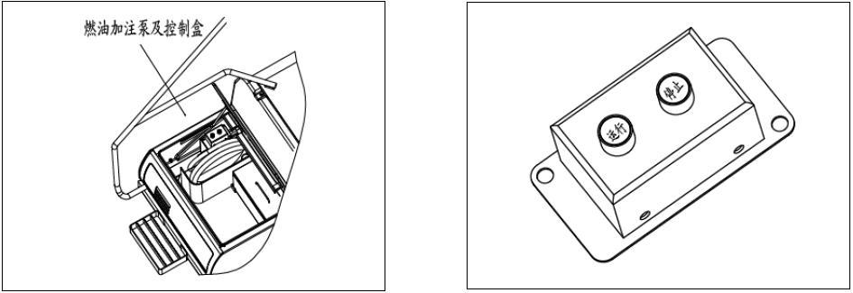
Checking steps for machine equipped with refueling pump: a). Open the cover of the fuel injection port(F),level gauge (G) rises with the oil level increasing. Check whether the fuel tank is full by looking the tank and check the level gauge (G). If the tank is not full, insert the suction pipe of the fuel filling pump into the tank (Figure 4-9), and turn on the machine power by the start switch. b) Press the green "Run" button on the refueling control box (Figure 4-10), and the refueling pump will enter into automatic refueling control state. The refueling pump will cut off automatically when the fuel tank is filled and then the entire refueling process ends c). If unforeseen circumstances take place during refueling process, you can press the red "Stop" button on the refueling control box and the refueling pump stops immediately; press the "Run" button again to continue to add fuel. d). When the pump stops running automatically due to unforeseen circumstances (e.g. the controller may mistake the tank for a full one due to fuel bubbles produced while fueling), press the "Run" button if the fuel tank is not yet fully fueled However, the pump only turns once at this press (to prevent fuel spillage), so repeat pressing the "Run" switch until the tank is full.
Discharge of water and sediment in the fuel tank:
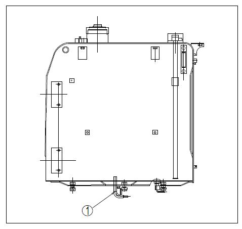
a). The water and sediments in a fuel tank is directly discharged through the drain valve set in the bottom, so you should put a container under the drain valve ① to receive the discharged fuel b). Open the drain valve ① at the bottom of the fuel tank and discharge the sediments and water accumulated at the tank bottom with the fuel. c). Close the drain valve ① when the discharged fuel is clean, as shown in Figure 4-11.

4.2.1.5 Check the oil-water separator
a). Open the right rear door of the machine.
b). Find the oil-water separator as shown in Figure 4-12 and put a container under the oil-water separator for oil discharge.
c) Open the drain valve ① at the bottom of the oil-water separator and discharge the water and sediments into the container.
1. It is recommended to discharge the sediments in the oil-water separator after the machine has worked for a whole day.
4.2.1.6 Check the hydraulic oil
1. The oil may erupt when the cap of the oiling port is removed, so you should turn the cap slowly to release the internal pressure before removing it.
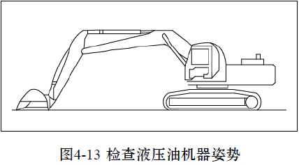
a). If the working device is not in the state shown in Figure 4-13, you should start the engine and keep it run at low speed. Retract the arm and bucket cylinders, and lower the boom and adjust the bucket teeth to have them contact with the ground, and then turn off the engine.
b). Turn the starter switch to the ON position within 15 seconds after the engine is shut down and fully operate the levers (for working device and traveling) in all directions to release the internal pressure. c). Open the right rear door of the machine and check the oil level gauge (G) from the inspection hole of the hydraulic oil tank. The oil level should be between the H line and L line, as shown in Figure 4-14. d). If the oil level is below the L line, you should add oil through the oil filling port (F) at the top of the hydraulic tank.

Attention
1. Do not add oil to a level above the H line, otherwise the hydraulic circuit may be damaged or oil ejection may be caused. If this happens, turn off the engine and discharge the excessive oil through the drain plug (P) when the hydraulic oil cools down.
Notes:
The oil level may change according to oil temperature as follows:
1). Before operation: the oil level is between H and L (oil temperature is 10 °C to 30 °C)
2). Normal operation: the oil level is close to H (oil temperature is 50 °C to 80 °C)
4.2.1.7 Check the electric circuits
Warning
1. If the fuse gets burnt frequently or there are signs of a short circuit, you should immediately identify the causes and carry out repair work or contact Zoomlion dealers.
2. The upper surface of the battery should be kept clean, ; check the vent on the battery cover and you should flush the battery cover and clean the vent if the vent is clogged by dirt or dust.
Checking items: a) Check if any the fuse is damaged or the capacity does not match, check whether there are signs of break or short circuit and check whether any terminal is loose and tighten the loose parts. b) Pay special attention while checking the wire lines of the "battery, starter motor and alternator. c) When conducting the patrol check or check before starting, be sure to check whether there are combustibles accumulated around the batteries and clear the combustibles. For investigation and correction of certain causes, please contact Zoomlion or Zoomlion dealer.
4.2.1.8 Check the horn
a) Turn the starter switch to the ON position.
b) Confirm that the horn rings immediately when being pressed. If the horn does not ring, please have it repaired by Zoomlion or Zoomlion dealer.
4.2.2 Operational qualifications before starting the engine
1. Before starting the engine, check to make sure that the safety locking lever is in the locked position shown in Figure 4-15. If the lever is not locked and accidentally touched when starting the engine, the working device will suddenly move and a serious accident may occur.
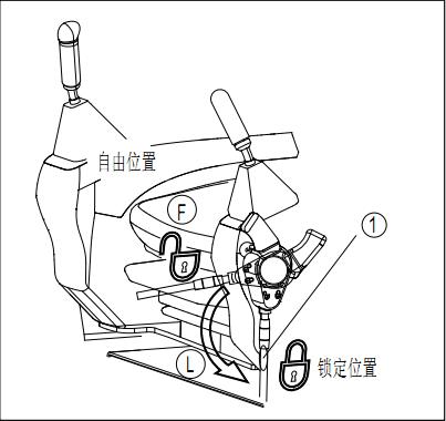
2. When the operator wants to stand up from the seat, be sure to put the safety locking lever ① in the locked position, no matter whether the engine is running or not. Check the position of all levers and put them in neutral positions.
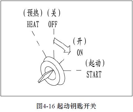
Steps for operational qualifications before starting the engine: a) Do not touch buttons and switches when starting the engine b) Insert the key into the starter switch as shown in Figure 4-16, turn the key to the ON position and then perform the following checks. c) Turn the starter switch from OFF to ON to switch on the electrical system. The display will complete startup automatically in about 10 seconds. d) If the starter switch is kept in the ON position, but the engine has not been started, it is normal that the “engine oil pressure too low” alarm and “battery voltage too low” alarm may be sent out. After the engine gets started, these alarm stops. e) During startup, initial states of various operating parameters are as follows:
Traveling speed: low speed
Automatic idling
Work mode: E mode
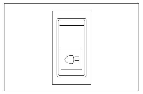
Warming-up: uncertain depending on the coolant temperature and system settings f) Press the light switch as shown in Figure 4-17 to check whether the headlamps are illuminated. If the headlamps don’t light up, the bulbs may have burnt out or may be open-circuited, so please contact Zoomlion or Zoomlion dealer for repair.
Safety locking lever: locked.
4.2.3 Start the engine
4.2.3.1 Normal start
1. Check whether there are people or obstacles in the surrounding area, and then honk the horn and start the engine.
2. As gas exhausted from the engine is harmful, paying particular attention to ensure good ventilation when starting the engine in an enclosed space.
Warning Prompt
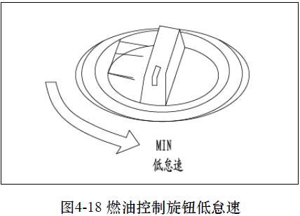
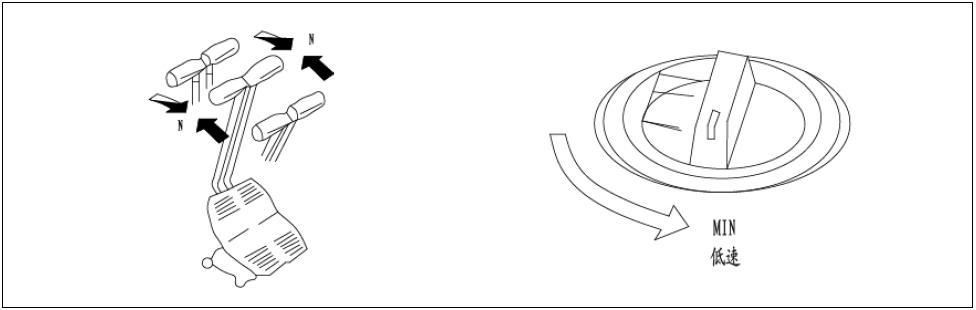
1. Before starting the engine, check whether the fuel control knob is in the position of the low idle speed (MIN).
2. Do not continuously operate the starter motor for more than 15 seconds.
3. If the engine does not start, wait at least two minutes and then restart.
4. If the fuel control knob is at the FULL position, the engine will suddenly accelerate, which may cause damage to the engine components. Therefore, the control knob should be adjusted to the medium-speed or low speed position.
5. After a vehicle gets started, it should run at idle speed for five minutes before it can work properly.
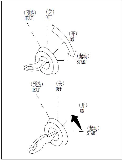
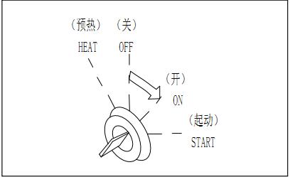
Normal engine start should follow these steps: a) Check whether the safety locking lever is in the locked position as shown in Figure 4-15; if not, the engine will not start. b) Turn the fuel control knob to the low idle speed (MIN) position shown in Figure 4-18. Turn the starter switch key to the START position shown in Figure 4-19 and the engine will start. c) When the engine is started, release the starter switch key and the key will automatically return to the ON position as shown in Figure 4-19. d) If the “engine oil pressure too low” warning light is still on as shown in Figure 4-20 after the engine is started, do not operate the levers for working devices and the traveling pedal
1. If the engine oil pressure indicator light is still on after 4-5 seconds (as shown in Figure 4-20), immediately shut down the engine, check the engine oil level, check for any oil leakage and take necessary measures.
4.2.3.2 Start the engine in cold weather
1. Check whether there are people or obstructions in the surrounding area, and then honk the horn and start the engine.
2. Do not use fluids that aid starting, because they may cause an explosion.
Please pay attention to the following when starting the engine in the cold weather: a). Check whether the fuel control knob is at the position of the low idle speed (MIN) before starting the engine. b). Do not continuously operate the starter motor for more than 15 seconds. c). If the engine does not start, wait at least 2 minutes, and repeat the operation from step 2. a) Check whether the safety locking lever is in the locked position as shown in Figure 4-15. Ifnot, the engine will not start. b) Turn the fuel control knob to the low idle speed (MIN) position. c) Turn the starter switch key to the START position to start the engine. d) When the engine is started, release the starter switch key and the key will automatically return to the ON position. e) If the “engine oil pressure too low” warning light is still on as shown in Figure 4-20 after the engine is started, do not operate the levers for the working device and the traveling pedal.
When starting the engine in cold weathers, do according to the following steps.
4.2.3.3 Operation after the engine was started
After starting the engine, do not immediately begin the operation. First, do the following operations and checks: a) Turn the fuel control knob to the center of thee low and high speed as shown in Figure 4-21, and run the engine for about 5 minutes under the no-load condition. b) Adjust the safety locking lever to the free position as shown in Figure 4-15, and raise the bucket from the ground. c) Slowly operate the bucket lever and lever of the stick as shown in Figure 4-22, move the bucket cylinder and bucket cylinder rod to stroke end. d) Operate the bucket and stick with full stroke for five minutes, converse between the bucket operation and stick operation each 30 seconds.

1. When withdrawing the working device, pay attention not to interfere with the body or on the ground. e) When preheating is performed, check if all instruments and indicators on the machine instrument controller are in the following states:
• Coolant level too low alarm: no
• Battery voltage alarm: no
• Fuel level to low alarm: no
• Coolant temperature alarm: no
• Oil pressure alarm: no
• Air filter blocked: no
• Hydraulic oil temperature alarm: not alarm
• Coolant thermometer: the pointer is within the blue region
• Hydraulic oil thermometer: the pointer is within the blue region
• Fuel level gauge: the pointer is within the blue area f) Check if there is any abnormal exhaust color, noise, or vibration, any abnormality found should be repaired. g) If the air filterblocked alarm flashes, you should immediately clean or replace the filter. See the Maintenance Manual for more details h)Select the work mode you prefer by using the POWER MODE botton on the instrument of the machine.
Operating mode instrument display:
P mode: for heavy-load operation, the whole machine runs in maximum working potential.
E mode: used for general operations.
L mode: for light-load operation mode, applied to the ground, slope operations, stick movement is gentler.
B mode: used for operations of accessories such as breaking hammer.
4.2.4 Engine warming-up and new machine running-in operation
For emergency stop under any circumstances or failures, turn the starter switch key to the OFF position
While operating the working device when the machine is not fully preheated, the reaction of the working devices to the movement of the lever will be slow and the device can not move in accordance with the requirements of the operator. So be sure to perform adequate warming-up operation, especially in cold areas.
4.2.4.1 Engine warming-up operation
1. When the hydraulic oil is at low temperature, do not operate the lever or move it suddenly.
2. Be sure to perform warming-up operation, which helps prolong the life of the machine.
3. Before the warming-up operation is completed, do not accelerate the engine suddenly.
4. Do not run the engine at low speed or high speed continuously for more than 20 minutes, otherwise it will cause oil leakage at the oil supply line of turbocharger. If you have to run the engine at idle speed, you should apply load from time to time to run the engine at medium speed.
4.2.4.1.1 Automatic warming-up operation (in cold area)
a) When starting the engine in cold areas, you should perform automatic warming-up operation before starting the engine.
b) If the engine coolant temperature is low (below 10 °C) when starting the engine, warming-up operation should be done automatically (this function needs to be set by entering user settings).
c) If the engine coolant temperature reaches the required temperature (30 ° C), the automatic warming-up operation will be canceled.
1. If want to cancel the warming-up operation in the warming-up process, tap the “cancel the warming-up operation” button on the monitor. (It is recommended that the user should not stop the warming-up operation at will, so as to prevent any damage to the machine.)
2. In the warming-up process, all levers do not work; only when the warming-up operation is finished or canceled, can the levers be operated and work properly.
3. When the hydraulic oil is still at low temperature, do not operate the machine or suddenly operate the lever. The warming-up operation should be continued till the hydraulic oil temperature rises to about 30 ℃, which helps extending the life of the machine.
4. Prior to the completion of the warming-up operation, do not accelerate the engine suddenly. Do not run the engine at low speed or high speed continuously for more than 20 minutes, otherwise it will cause oil leakage at the oil supply line of turbocharger. If you have to run the engine at idle speed, you should apply load from time to time to run the engine at medium speed.
4.2.4.1.2 Manual warming-up operation
If the user wants to operate warming-up manually, please follow these steps: a) Turn the fuel control knob to the medium speed position as shown in Figure 4-21. b) Put the safety locking lever to the free position and raise the bucket from the ground. c) Slowly operate the bucket control lever and arm control lever to move the bucket cylinder and arm cylinder rods to stroke end. d) Operate the bucket and arm for five minutes; switch between bucket operation and arm operation with a cycle of 30 seconds. e) After the warming-up operation is performed, check whether all gauges and indicator lights on the monitor and controller are in the following states:
1. when retracting a working device, be careful not to interfere with the machine or the ground.

• Coolant level too low alarm: no alarm
• Battery voltage too low alarm: no alarm
• Fuel level too low alarm: no alarm
• Coolant temperature too high alarm: no alarm
• Engine oil pressure too low alarm: no alarm
• Air filter blocked alarm: no alarm
• Hydraulic oil temperature too high alarm: no alarm
• Coolant thermometer: the pointer is within the blue area
• Hydraulic oil thermometer: the pointer is within the blue area
• Fuel level gauge: the pointer is within the blue area
Check steps: a) Check whether the color of exhaust, noise and vibration are normal; any abnormality found should be repaired. b) If the “air filter blocked” indicator light flashes, you should immediately clean or replace the filter. See the maintenance manual for the method of cleaning filter c) Turn the fuel control knob to the high-speed (MAX) position, as shown in Figure 4-23 and perform a 3-5 minute check to see whether all gauges and instruments are in normal states. d) Repeat the following operations 3-5 times and operate slowly.
Boom operation lift lower
Arm operation retract extend Bucket operation digging unload
Slewing operation turn right turn left Traveling (low speed) operation forward backward e) Select the work mode to be used with the power mode button on the monitor.
Notes:
Without the above operations, there will be a delay in reaction when starting or stopping an operating mechanism and you should continue the operation until it becomes normal.
4.2.4.2 New machine running-in
1. Before delivery, the Zoomlion machines have gone through thorough debugging and testing. However, operation of a machine started in harsh conditions may have adverse effects on the machine’s performance and shorten its service life.
2. In the first 100 hours (according to the hour meter), be sure to run in the machine A new machine can only run at high gear after passing the run-in period. During the running-in operation, you should comply with the precautions listed in this manual.
Precautions: a) After starting the engine, you should keep it running at idle speed for 15 seconds and do not operate the lever or the fuel control knob now b) After the engine is started, it should run for 5 minutes at low speed. c) Avoid heavy-duty operation or high-speed operation; instead, the machine should be run in with a load of about 80% of the maximum load. d) Except in emergencies, sudden startup, acceleration, turn and stop should be avoided. Without run-in operation, sintering or stuck fault may occur, which will greatly shorten the service life of the machine.
4.2.5 Shut down the engine
1. If the engine is abruptly shut down without being cooled down, its service life will be greatly shortened. Therefore, do not shut down the engine suddenly unless an emergency takes place.
2. Do not shut down the engine suddenly especially when the engine is overheating; instead, keep it running at medium-speed till the engine gradually cools down and then shut down the engine.
Steps for engine shutdown: a) Run the engine at low speed for about 5 minutes, so that the engine gradually cools down b) Turn the starter switch key to the OFF position as shown in Figure 4-24 to turn off the engine. c) Remove the starter switch key.
4.2.5.1 Checks after shutting down the engine
Check according to the following steps: a) Conduct an inspection of the machine on the working devices and the upper and lower parts of the machine. Check for oil or water leaks. For any abnormalities found, repairs should be done. b) Check whether there are any paper scraps and debris in the engine room; clear them (if any) to avoid a fire hazard. c) Remove the soil adhering to the lower part of the machine
4.3 The excavator operating techniques
4.3.1 Transfer of excavator
Turn the fuel control knob to high-speed position to increase engine speed, as shown in Figure 4-23.
Warning
1. Check the direction of the crawler frame before operating steering lever.
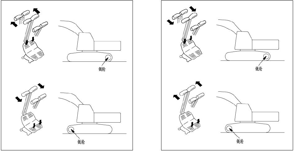
2. If the sprocket is in the front, the operation of the traveling lever is in the opposite direction.
3. Before moving the machine, please ensure that it is safe around the machine and honk the horn.
4. Do not let anyone get close to the surrounding area of the machine.
5. Clear all obstacles in the route of traveling.
6. The rear of the machine is a blind area, so please pay special attention during backing-up.
7. When the auto-idle function is activated, the engine speed will suddenly increase if you operate the lever, so be careful in the operation.
8. For a machine with a traveling alarm (optional), you should check whether the alarm device is working properly.
4.3.1.1Move the machine forward
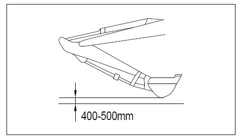
Steps for moving the machine forward are as follows: a) Put the safety locking lever to the free position, fold the working device and lift it off the ground for 400 to 500mm (16-20in) as shown in Figure 4-25. b) When the sprocket is in the rear of the machine, slowly move the lever forward or depress the front of the pedal to move the machine (Figure 4-26). c) When the sprocket is in the front of the machine, slowly move the lever backward or depress the rear of the pedal to move the machine.
Notes:
If the machine’s traveling speed is abnormal in cold weathers, carry out a thorough warming-up operation.
In addition, if the lower part of the machine is clogged by soil, the machine may not move with normal speed, so you should remove the dirt and mud.
4.3.1.2 Move the machine backward
a) Put the safety locking lever to the free position, fold the working device and lift it off the ground for 400 to 500mm (16-20in).
b) Operate the left and right traveling levers or the left and right traveling pedals as follows:
• When the sprocket is in the rear of the machine, slowly move the lever backward or depress the rear of the pedal (Figure 4-27) to move the machine.
• When the sprocket is in the front of the machine, slowly move the lever forward or depress the front of the pedal to move the machine
Notes:
• If the machine’s traveling speed is abnormal in cold weathers, carry out a thorough warming-up operation.
• In addition, if the lower part of the machine is clogged by soil, the machine may not move with normal speed, so you should remove the dirt and mud.
Driving wheel
Driving wheel
4.3.1.3Braking operation
Warning techniques of the excavator
S afe operation and operating
Driving wheel
Driving wheel
1. Avoid sudden stop of the machine and keep safe parking distance. Place the left and right levers in the neutral position as shown in Figure 4-28 and then stop the machine.

Warning
1. Before operating the traveling lever, you should check the location of the sprocket. If the sprocket is in the front, the lever operation should be in the opposite direction.
Change the direction by operating the traveling lever, as shown in Figure 4-29.
Avoid a sudden change of direction, especially when performing a reverse rotation (turning on the spot); stop the machine before turning.
4.3.2.1 Turning when the machine stops
For turning left, the operating method is as follows:
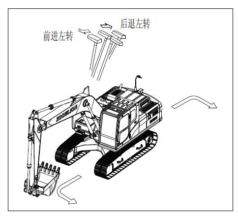
When traveling forward, move the right traveling lever forward and the machine turns left. When traveling backward, move the right traveling lever backward and the machine turns left (See Figure 4-30)
4.3.2.2 Turning during driving
Return the left traveling lever to the neutral position and the machine will turn left, as shown in Figure 4-31.

1. Return the right traveling lever to the neutral position and the machine will turn right.
4.3.2.3 Turning on the spot
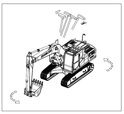
If you want to turn the machine to the left on the spot, move the left lever backward and move the right lever forward, as shown in Figure 4-32.
1. If you want to turn the machine to the right on the spot, move the right lever backward and move the left lever forward.
4.3.3 Control and operation of the working device
1. If you operate the lever when the auto-idle function works, the engine speed will suddenly rise, so pay special attention to the lever operation.
2. If you operate the lever for the working devices in a fast way, the working device will move quickly; if you slowly operate the lever for the working devices, the working device will move slowly.
The working devices are controlled by the left and right levers for working devices. The left lever controls the arm and slewing; the right lever controls the boom and the bucket. The movements of the lever and the working devices are shown in Figure 4-33. Release the lever and it will automatically return to the neutral position, and the working devices will stop moving. When the machine is stationary and the lever for the working devices is placed in the neutral position, the engine will always run at low speed even if the fuel control knob is turned to MAX position due to automatic idling function

The working devices can be lowered to the ground if you operate the lever within 15 seconds after shutting down the engine. You can operate the lever to release the residual pressure within the hydraulic circuit and lower the boom when the machine is loaded on a trailer.
4.3.3.1 Bucket arm operation
Move the left lever for the working devices forward or backward to operate the arm as shown in Figure 4-33.

4.3.3.2 Slewing operation
1. For the rear part of the machine extends beyond the track width, you should check whether the surrounding area is safe before slewing the upper structure.
2. Operate the slewing lever fast and the superstructure will turn quickly; slowly operate the slewing lever and the superstructure will turn slowly.
Operate the left lever for the working devices to control the slewing operation, as shown in Figure 4-34. When the lever is in N (neutral) position, the spring brake is working. Move the left lever to the left or right to slew the upper structure.
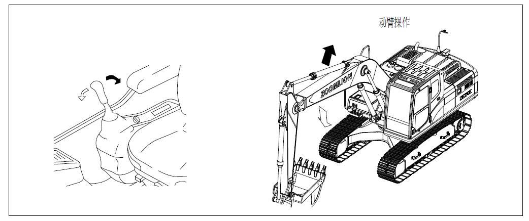
4.3.3.3 Boom operation
Move the right lever for the working device forward or backward to operate the boom, as shown in Figure 4-35.
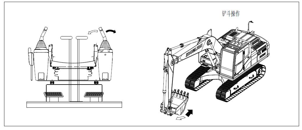
4.3.3.4 Bucket operation
Move the right lever for the working devices to the left or right to operate the bucket, as shown in Figure
4.3.3.5 Bucket replacement
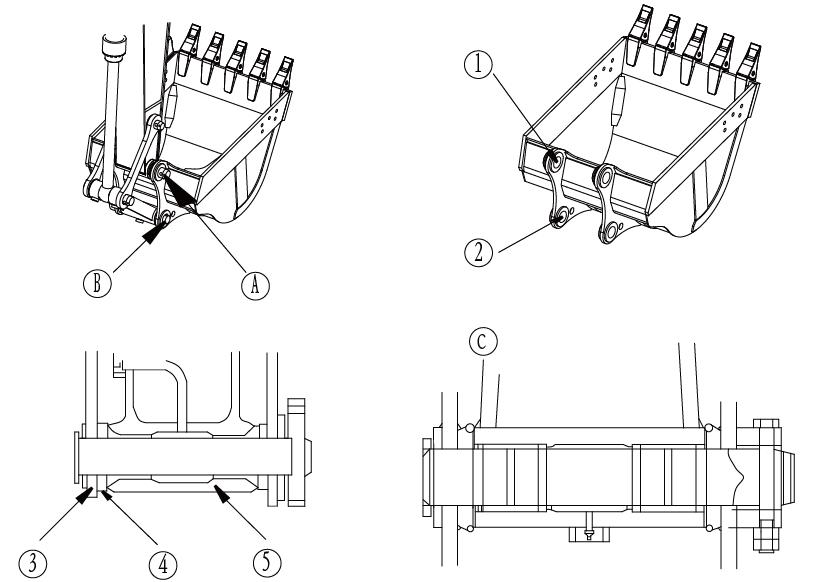
Warning a) Lower the bucket on a flat ground. b) Remove the double nuts from the lock bolt for each pin on the arm and rod to remove the bolt, and then remove the arm pin (A) and the connecting rod pin (B) to remove the bucket, as shown in Figure 4-37 c) Align the arm with the hole ① and the connecting rod with the hole ②, coat them with grease and install the pin (A) and (B).
1. When you strike the pin with a hammer, metal shavings may fly into the eyes, causing serious injury. When conducting this operation, always wear goggles, helmets, gloves and other protective equipment.
2. Remove the bucket and put it away.
3. If you strike hard at the pin, the pin may fly out and injure personnel in the surrounding area. Therefore, make sure the surrounding area is safe before striking the pin.
4. When you disassemble the pin, pay special attention not to stand under the bucket and not to put your feet or any part of the body below the bucket.
5. When removing or installing a pin, be careful not to bruise the hand.
6. When aligning the pin with the hole, do not put fingers into the pin hole.
Park the machine on a solid and flat ground. When doing the connection work, fully understand the signals and work carefully to ensure safety.
1. When disassembling the pin, place the bucket in a position just contacting with the ground.
2. If the bucket completely falls to the ground, resistance will increase so that it will be difficult to remove the pin.
1. Remove the pin and make sure that the pin will not be contaminated by sediments and the seals at both ends of the shaft sleeve are not damaged.
Notes:
1). The installation of the device is in reverse order with the dismantling.
2) Before installing the bucket, install an O-ring at the arm pin location on the bucket as shown in the picture. Insert the pin and put it into the appropriate slot. At the location of the connecting rod (B), install the bucket in case that the O-ring is mounted into the appropriate slot.
3). Install the lock bolts and nuts for each pin, and then coat the pins with grease.
4.3.4 Work modes
4.3.4.1 Power mode:
When the starter switch is turned to the ON position, the power mode is set to the E mode, and you should select the mode that matches with the working conditions through the Work Mode switch as shown in Table 4-1, so as to carry out effective operations.
Table 4-1 Work mode and corresponding range of application
Work mode
P mode
Range of application
Heavy-load mode: the complete machine can give full play to its maximum working potential.
E mode Standard mode: the power input of the complete machine is about 85% of the engine's maximum power
L mode
Light-load mode: the power input of the complete machine is about 65% of the engine's maximum power
B mode Used for operations with such auxiliary devices as breaking hammer.
4.3.4.2 Power enhancing button:
a) During operation, in order to increase the power, you can use the touch-style power enhancing switch shown in Figure 4-38. This function should be used effectively in view of the working conditions whenever necessary b) Press the button shown in the right and power will increase. However, the increased power will automatically be cancelled in 8 seconds c) After a power increase, another power increase can only be done after an interval of three seconds.
4.3.5 Prohibited operations
1. If you have to operate the lever for the working devices when the machine is traveling, you should be especially careful with the operation.
2. If you operate any of the levers when the automatic idling works, the engine speed will be suddenly increased, so be careful.
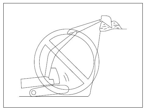
4.3.5.1 No operation with slewing force
Do not use slewing force to compact the ground or break objects. This is not only dangerous but also will significantly shorten the life of the machine or damage the machine (see Figure 4-39).
4.3.5.2 No operation with traveling force
Do not dig the bucket into the earth and excavate with traveling force, for this will damage the machine or working devices.
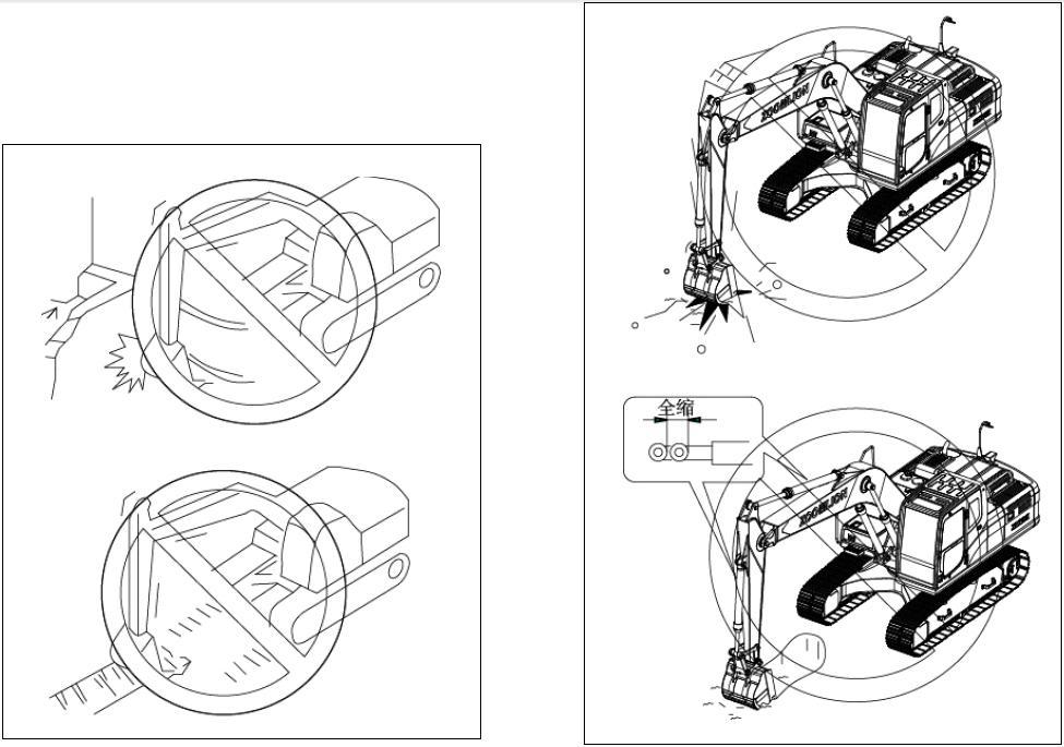
4.3.5.3 No operation with the hydraulic cylinder fully extended or retracted
During operation, do not apply force on a hydraulic cylinder that is fully extended or retracted, for this will cause impact on the working devices and damage the hydraulic cylinder (see Figure 4-40)

4.3.5.4 No operation with falling force of bucket
Do not use the falling force of bucket for digging or use a falling bucket as pickax, breaker or piling machine, for this will significantly shorten the life of the machine (see Figure 4-40)
4.3.5.5 No operation with falling force of machine
Do not dig with the falling force of machine, as shown in Figure 4-41
4.3.5.6 No excavation of hard rock ground
Do not use excavators to dig hard rocky ground and you had better excavate after the ground is crushed with other methods. This will not only reduce the damage to the machine but also is economical.
4.3.5.7 Jerky operation of lever at high traveling speed
1. Do not move the lever jerkily, otherwise it will cause a sudden start, shown in Figure 4-42.
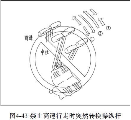
2. Avoid moving the lever from the forward to backward position suddenly (or from backward to forward position).
3. Avoid jerky lever operation, such as releasing the lever to stop the machine when it is traveling at high speed.
4.3.5.8 No hoisting operation
Under general circumstances, the machine is prohibited to be used as crane. Please contact Zoomlion or its authorized agent for details.
4.4 Safe operation
4.4.1 Safe traveling
When traveling on such obstacles as gravels and stumps, the machine (especially the lower part) will suffer from great impact, as shown in Figure 4-43. Therefore, driver should reduce the driving speed and keep the center of the track cross over the obstacles. Try to remove such obstacles or avoid driving on them.
The machine should travel at low speed on such uneven roadbed as stone embankment or uneven road with large stones. When the machine is traveling at high speed, the idler should be set in forward direction.
To change speed, press the traveling speed selective switch. The track icon is displayed on the monitor to display the traveling speed
4.4.2 Allowed water depth
1. If the inclination of the machine is larger than 15 °C when the machine walks out from water as shown in Figure 4-44, the rear of the superstructure will dip into the water and the cooling fan will screw the water, resulting in radiator damage.
2. Be especially careful when driving the machine out of water.
3. Do not drive the machine in water with level higher than the centerline of the sprocket ①.
4. Apply grease on parts which have already soaked underwater for a long time until the old grease is completely squeezed out (especially around the bucket pins).
4.4.3 Traveling on the slopes
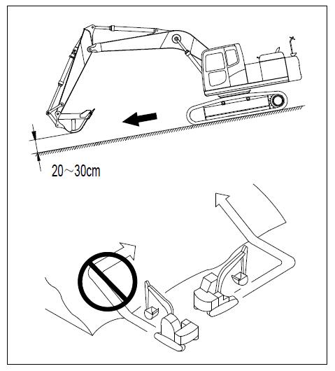
1. When driving, raise the bucket off from the ground for about 200 - 300 mm (8-12in) and do not travel downhill backward.
2. When the machine is traveling on bumps or other obstacles, make sure that the working device gets close to the ground and drive slowly.
3. Do not turn on slopes or travel across the slope as shown in Figure 4-45. These operations must be carried out on a further but safer flat ground.
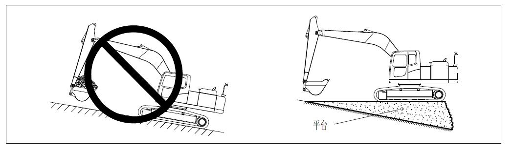
4. When the machine is working on slopes, turning or operating working devices will make the machine lose balance and overturn, so this operation should be avoided.
5. When the bucket is loaded, slewing towards the downhill direction is very dangerous. If you must carry out this operation, you should pile up a platform with soil on the slope, so as to keep the machine in balance during operation.
6. Do not drive uphill or downhill on steep slopes, for the machine may risk overturning.
7. When traveling uphill, if the track shoe slips or cannot travel with only track force, do not travel with the help of arm’s pulling force as shown in Figure 4-46, since this may cause machine overturning.
When traveling downhill, drive the machine at low speed by operating the traveling lever and fuel control knob. When traveling downhill on a steep slope with an angle larger than 15 °, the working devices should be adjusted to the state shown in Figure 4-47 and the engine speed should be reduced
Note: if the sprocket side faces downward when the machine goes downhill, the crawler will often slack, resulting in risk of gear jumping;
Platform
• When the machine is going uphill, in order to ensure balance, you should stretch the working devices forward and keep them away from the ground for 200-300 mm (8-12in) and drive at low speed.

• When the machine is going downhill, in order to brake the machine, the traveling lever should be placed in the neutral position, so that the machine will automatically stop.
• If the engine is shut down when the machine is going uphill, all levers should be put in the neutral positions before restarting the engine.
Warning
1. If the engine is shut down when the machine is traveling on a slope, do not perform slewing operation by operating the left lever for the working devices. The superstructure will rotate under its own weight.

2. When opening or closing door on a slope, be especially careful that the door will suddenly open or close due to its own weight. Make sure that the door is firmly locked.
4.4.4 Escape from the mud
Always be careful to avoid falling into the mud. If the machine falls into the mud, drive it out according to the following steps.
a) One track has fallen into the mud:
1. When the machine is lifted by the boom or arm, be sure that the bottom of the bucket contacts with the ground (Do not use the bucket teeth to push). The angle between the boom and the arm should be between 90 ° and 110 °. These rules are also applicable when using the bucket that is reversely installed.
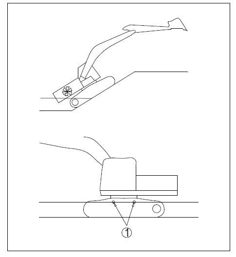
2. If only one track has fallen into the mud, lift the crawler with the bucket, and then pad wood or logs to drive the machine out of the mud. If necessary, also place wood under the bucket, as shown in Figure 4-48 b) Both tracks have fallen into the mud:
If both tracks are in the mud, slip and can not move, pad logs or timbers as described above. Dig the bucket into the ground in front, operate the arm in the same way as digging operation and move the traveling lever to the forward position to pull out the machine, as shown in Figure
4.4.5Stop the excavator
Warning
1. Avoid sudden stop of the machine and leave adequate space for parking the machine.
2. Park the machine in solid and flat ground.
3. Avoid parking the machine on the slopes.
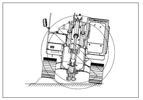
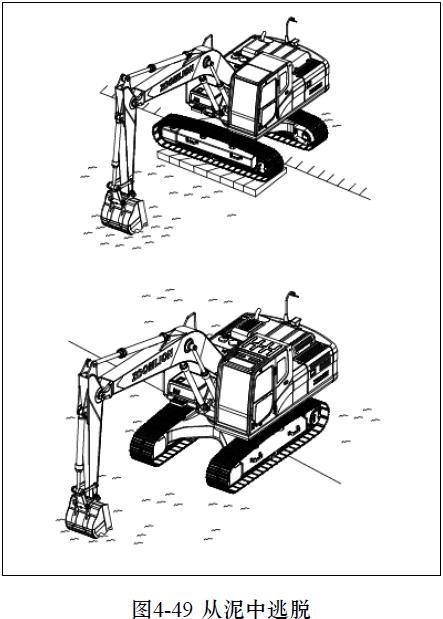
4. If you must park the machine on a slope, pad the crawler with blocks and insert the working device into the ground to prevent machine movement, as shown in Figure 4-49.

5. If you accidentally touch the lever for the working devices, the working device or the machine will suddenly move, causing serious personal injury or accident. Therefore, before standing up from the seat, make sure that the safety locking lever is firmly placed in the locked position.
Steps for parking the machine: a) Place the left and right traveling levers in the neutral positions to stop the machine. b) Turn the fuel control knob to reduce the engine speed to low speed, as shown in Figure 4-50 c) Lower down the bucket horizontally, until the bottom of the bucket touches the ground, as shown in Figure 4-51 d) Place the safety locking lever in the locked position.
4.4.6 Operation in special weather
4.4.6.1 Operation in cold weather
If the temperature is low, the engine will not start easily and the coolant will freeze, so follow these steps: a) Fuel and lubricants b) Coolant
All the components should use fuel and lubricants with low viscosity. Please refer to the maintenance manual for details about the velocity.
The antifreeze is toxic, so be careful not to let the antifreeze splash into the eyes or on the skin. If any antifreeze splashes into the eyes or on the skin, you should rinse with a lot of clean water to and seek medical care immediately.
1. The antifreeze is toxic, so be extremely careful when you deal with it. Before replacing antifreeze or dealing with coolant when repairing radiator, please contact Zoomlion distributor or local antifreeze suppliers. Be careful not to allow the liquid flow into sewers or onto the ground. c) Battery
2. The antifreeze is flammable, so keep it away from fire and do not smoke when dealing with antifreeze.
1. Do not use methanol, ethanol or propanol-based antifreeze.
2. Avoid the use of any leak-proof agents absolutely, whether being used alone or mixed with antifreeze.
3. Do not mix different brands of antifreeze.
During cold seasons, only ethylene glycol antifreeze which does not contain preservatives is available in the region where permanent antifreeze is out of reach. In this case, the cooling system should be cleaned twice a year (spring and fall). When filling the cooling system, antifreeze should be added in the fall instead of in the spring.
About antifreeze mixing ratio for replacing the coolant, see "Maintenance Manual".
1. The battery produces flammable gas, so keep it away form fire or sparks.
2. The battery electrolyte is dangerous. If it enters into eyes or skin, you should rinse with a lot of water and go to a doctor immediately.
3. The battery electrolyte dissolves the paint, so you should immediately wash the machine with water if the electrolyte is sprinkled on the machine.
4. If the battery electrolyte is frozen, do not charge the battery or start the engine with different power sources, because this may result in risk of battery explosion.
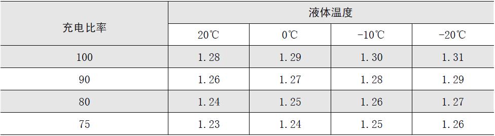
5. When the ambient temperature drops, the battery capacity declines. If the battery charge ratio is low, the battery electrolyte will freeze. So maintain the battery charge capacity close to 100% and isolate battery from low temperature, so that the machine can be easily started next morning.
Notes:
1). Measure the proportion of electrolyte and get the converted charge ratio from Table 4-2.
2). At low temperatures, the battery capacity will significantly decrease, so pack the battery or remove it from the machine to a warm place, and load it into the machine next morning.
3). If the electrolyte level is low, add distilled water to it in the morning before starting work. Do not add water after finishing the daily work so as to prevent the liquid inside the battery from freezing at night.
4.4.6.2 Operation in snow weather
Surface covered with snow or frozen is very slippery. Be especially careful when operating machinery. Do not impose sudden operation on the lever.
Even small slopes may make the machine slip. Therefore, when operating on slopes, particular attention should be paid.
a) For the frozen ground, the ground becomes soft when the temperature rises,, which may cause machine overturning b) If the machine falls into deep snow, there will be risk of overturning or being buried in the snow. Be careful not to leave the road shoulder or fall into the snow. c) When cleaning the snow, road shoulder and nearby objects are buried in the snow and can not be seen, so the machine may overturn or hit the buried objects, so be sure to operate carefully.
When the season changes and weather gets warmer, do according to the following steps:
Replace the fuel and engine oil of all components with the specified viscosity. See "Maintenance Manual" for details. If only ethylene glycol-based antifreeze (for winter use) is available instead of permanent antifreeze or if there is no antifreeze, the cooling system should be cleaned completely, then clean the internal cooling system thoroughly and add fresh soft water.
4.4.7 Work after operation
4.4.7.1 Check and clean the machine
Check the engine coolant temperature, hydraulic oil temperature and fuel oil level on the monitor, so as to clear the mud and water on the lower part of machine. Besides, the following steps should be performed: a) The engine works at low speed, slew the machine for 90 °to turn the working devices to one side. b) Jack up the machine, so that the crawler is slightly lifted off the ground, and then idle the crawler.
Repeat the operation for the left and right tracks
1. Crawler idling is dangerous, so stand as far as possible from the crawler.
2. When the operation is completed, fill the fuel tank to prevent the formation of water when the temperature drops due to condensation of moisture in the empty box.
To prevent mud and water from getting frozen on the lower part of the machine and causing that the machine can not move in the next morning, observe the following precautions: a) Completely clear mud and water off the machine, so as to prevent damage to the seal due to mud and dirt flowing into the seal along with water. b) The machine should be parked on the hard and dry ground. If possible, park the machine on wood which can prevent the crawler from being frozen in mud, so that the machine can start next morning c) Open the drain valve to discharge water accumulated in the fuel system to prevent freezing
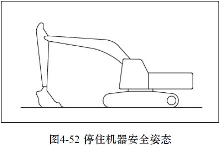
4.4.7.2 Lock
Lock these parts, as shown in Figure 4-52:
① Engine hood
②. Left door of the machine
③ Cab door
④ Battery cover
⑤. Oiling port of the fuel tank
⑥ Right door of the machine
⑦ Oiling port of the hydraulic tank
ZE205E/ZE230E
Operation Manual
Chapter Five:Accessories and options
Chapter Five:Accessories and options
5.1 General Notes
5.1.1 Safety precautions
a) The installation of options and accessories concerns security or legal constraints, so please contact Zoomlion or Zoomlion dealer in advance Otherwise, we assume no responsibility for accident or damage.
b). Zoomlion will not be responsible for any injury, accident or product failure caused by accessories or options used without Zoomlion’s approval. These accessories or options will not only affect the life of the machine, but also cause potential security hazard.
c) When installing and using the optional accessories, read relevant parts instructions and general notes in this manual about the accessories.
1. The accessories are powerful tools. Please use them in the correct way in order to prevent serious injury or damage.
2. Read through the instruction manual of the accessories and do not use the accessories until you completely understand the contents of the manual. If you have lost the instruction manual, you may request the manufacturer or accessories sales company for a new one.
3. According to the accessory’s condition, shield should be installed on the front of the machine if necessary.
4.Vibration and noise may make it difficult for coworkers to convey the instructions. Before you begin, assign a commander and determine the signal to be used.
5. When the accessory is bearing heavy load, do not slew to the side and it is very dangerous to do so on slopes.
6. Compared to the machine with the bucket, the machine equipped with a breaker bears a heavier and unstable load in the front of the working device. Do not operate the machine when the accessory turns to the side, so as to prevent overturning.
7. When accessories are installed, the slewing scope and gravity center of the machine is not the same and the machine may move accidentally. So you must fully understand the machine’s conditions
8. Before operation, set a cordon around the machine to prevent persons from entering. Do not operate the machine when any people is nearby.
9. In order to prevent serious accidents caused by wrong operations do not put your foot on the pedal except that when you are operating the pedal.
5.1.2 Precautions for disassembling and installation operation
When disassembling or installing the accessories, be sure to do according to the following steps in order to ensure safe operation:
1. Carry out disassembling and installation operations on a solid and flat surface.
2. When there are more than two people involved in the operations, determine the signals and comply with these signals in operation.
3. When lifting or handling heavy objects (over 25 kg or 55lb), be sure to use a crane.
4. When removing heavy components, support them before removal. When the crane is doing lifting job, pay special attention to the location of the gravity center.
5. Operation while the crane is lifting load is dangerous. A bracket should be set to ensure safety.
6. When placing the removed accessories or when mounting the accessories, make sure they are in stable condition and will not tip over.
7. Do not walk under the load lifted by the crane, and stand at a place where there is no danger even if the load falls.
1. A qualification certificate is necessary for operating cranes. Do not allow unlicensed personnel to operate cranes
2. For operation details of removal and installation, please contact Zoomlion or Zoomlion dealer.
5.1.3 Precautions for accessory installation
Long device will reduce the stability of the machine, so if slewing operation is done on slopes or when the machine is walking downhill from steep slopes, the machine will lose balance and tip over.
The following operations are particularly dangerous, so do not operate the machine in the following manner: a) If a heavy device is mounted on the machine, the slewing distance will increase (there will be a distance between the expected stop position by lever operation and the position where the upper structure completely stops). As a result, there will be risk of wrong judgment of distance or risk of hitting certain objects. So there should be room left for the upper structure to stop. In addition, hydraulic drift will increase (when the working device is stopped in mid-air, it will decline under its own weight) (Figure 5-1). b) When installing the boom and arm, be sure to follow the correct procedures. If not, it may cause serious damage or injury. Therefore, please contact with Zoomlion or Zoomlion dealers during installation. c). If a long working device is mounted on the machine, the operating range will suddenly get larger, so there will be misjudgment of distance and risk of hitting certain objects. When operating a working device, be sure to leave some space for any object within the region (Figure 5-2).
5.2 Options and accessories operation guides
1. Please read the accessories instructions and related sections in this manual.
2. Installation of accessories or options concerns security issues. Therefore, prior to installation, please contact Zoomlion or Zoomlion dealers.
3. Zoomlion will not be responsible for accessories or options used without Zoomlion’s approval. These accessories or options will not only affect the life of the machine, but also cause potential security hazard, resulting in injury, accident or product failure.
4. Zoomlion will assume no responsibility for any harm, accident or damage caused by the use of unauthorized accessories or options.
5.2.1 Combination of the working device
1. According to the type or combination of working devices, there may be risk of the working device’s collision on the cab or machine body.
2. Before using unfamiliar device for the first time, be sure to check whether there is any risk of interference and be careful in operation.
Table 5-1 lists all the accessory combinations which can be installed to long stick (standard), short stick, and bucket.
Notes:
1) Symbols in table 5-1 represent respectively:
●: For operation of materials with density no more than 2000kg / m³
◎: For operation of materials with density no more than 1800kg / m³
○: Operation of materials with density no more than 1500kg / m³
△ : Operation of materials with density no more than 1200kg / m³and only for loading
2) Use category
General digging: digging or loading of sand, gravel, clay.
Light-load digging: digging or loading of dry, loose soil and sandy soil, sludge, etc.
Loading: loading of dry, loose soil and sand.
1. When the arm is lengthened, it will interfere with the bucket if the bucket gets close to the machine. Be careful to operate lengthened arm.
2. During bevel digging, the boom will interfere with the lower part of the machine when the boom is completely lowered down. Be careful to operate the boom.
3. For excavation or loading of hard soil or rock, it is recommended to use the reinforced bucket with high strength and high wear resistance.
5.2.2 Track shoe selection
Please select appropriate track shoe suitable for operating conditions. Determine the category according to their uses listed in Table 6-2, and then select the appropriate track shoe in table 5-3
1. B-type and C-type are wide track shoes, so their uses are restricted. When using these track shoes, a thorough investigation and study should be carried out on the conditions of use, so as to determine whether these track shoes are applicable.
2. When selecting the width of track shoe, try to select the narrowest track shoe according to the floatability and ground pressure. If the width of the track shoe used is larger than that of the required, the load of the track shoe will increase and the track shoe may have the risk of plate bending, chain breakage, pin breakage, loose bolts and other problems.
Type Use
A Stone ground, riverbed, common soil
B Common soil, soft ground
Precautions for use
Travel at low speed on rough ground with large obstacles such as boulders and fallen trees.
These track shoes can not be used for traveling on rough ground with large obstacles such as boulders and fallen trees.
Travel at high speed or medium speed on level ground only; if it is inevitable to cross an obstacle, slow down and travel at half of the slow speed.
They are applicable only when the machine subsides at places where A or B track shoe is not applicable.
C Very soft ground (swamp surface)
These track shoes can not travel on rough ground with large obstacles such as boulders and fallen tree.
Travel at high speed or medium speed on level ground only; if it is inevitable to cross an obstacle, slow down and travel at half of the slow speed.
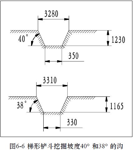
5.2.3 Use of trapezoidal bucket
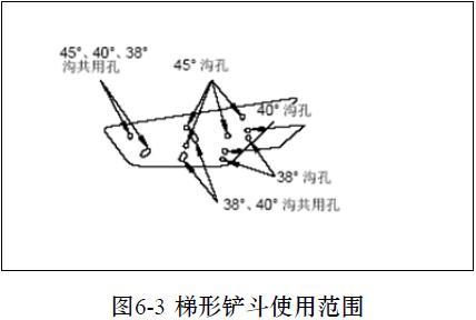
This bucket is used for digging trapezoidal ditches on farmland etc. With a mobile board equipped, it can dig three kinds of ditches (45 °, 40 °and 38 °) (Figure 5-3)
The mounting position of the mobile board changes according to the trench slope ( 45 °, 40 °or 38 ° ) a) Digging steps:
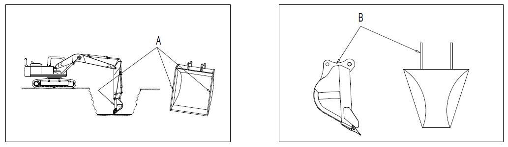
1) Operate the boom, arm and bucket to keep the line at the side plate of the bucket (A) vertical to the ground, as shown in Figure 5-4. b) Digging of ditch with a slope of 45 ° c) Digging the ditch of the 40 °and 38 °slope
2). Check the guide plate (B) at this position and ensure that it is installed next to the bucket pin, as shown in Figure 5-5. Keep the plate horizontal when digging.
Select the corresponding ditch hole, mount on the bucket or mobile board, and perform the excavation with the above method.
Select the corresponding ditch hole, mount on the mobile board, and perform the excavation according to the above method (Figure 5-6).
Even if the trapezoidal bucket is equipped with a mobile board, excavation should still be done under the condition that the bucket side is perpendicular to the ground.
5.2.4 Use of the lengthened arm
When the machine is equipped with lengthened arm (Figure 5-7), retracting the arm may cause the bottom of the boom cylinder and the turntable interfere with the bucket, so please pay attention to the following points during operation and transportation: a) When the machine is equipped with a lengthened arm, you should use the narrow bucket without side cutting edge. b) Working on hard ground or rocky ground will shorten the service life of the lengthened arm, boom and arm

The standard bucket will make the machine unstable and the retracting of arm may make that the bucket and the cab interfere with each other, so do not install the standard bucket.
In this case, you’d better not use lengthened arm
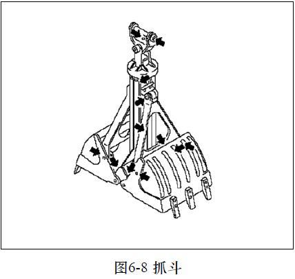
5.2.5 Use of grab a) Digging method b) Precautions for use
This grab (Figure 5-8) is used for excavation or loading at one side of the trench or a confined space.
This grab excavates by pushing the boom towards the ground.
During the grab operation, carry out excavations at the same time when the boom is gradually rising.
If the grab rotates, you should release the bucket cylinder pressure and then adjust the lever to the neutral position so that it temporarily stops rotating.
Warning c) Lubrication
1. For your safety, be sure to avoid sudden traveling, rotation and stop.
2. Dig with the bucket teeth remaining vertical.
3. Do not crush stones or cut into the soil by way of the slewing grab.
4. Do not pile or pull pile with the bucket.
5. Before leaving the machine, open the grab, and lower it onto the ground.
Note: During the transport of the machinery, the grab should be removed from the stick.
Prepare a grease gun.
1). Stop the machine on hard and level ground, lower the working device to the ground and turn off the engine.
2). Pump in the grease with the grease gun through the grease nozzle indicated by the arrow.
3). After lubrication is done, wipe the old grease being squeezed out.
5.3 Operation of recommended options
This section describes the precautions to be observed for operation of machine equipped with the options (mainly hydraulic excavator hydraulic hammer).
1. Select the accessories that are suitable for the machine.
2. Machine models for accessory installation are different. For selection of accessories and machine model, please contact Zoomlion or Zoomlion dealers.
5.3.1 Hydraulic hammer
5.3.1.1 Purpose of hydraulic hammer
Hydraulic hammer can be used for a wide range of operations, including building demolishing operations, road crushing operations, tunnel work, slag breaking operations, stone breaking operations and crushing operations at quarries
5.3.1.2 Precautions for using hydraulic hammer
1. For installation of hydraulic hammer, be sure to contact Zoomlion or authorized Zoomlion dealers.
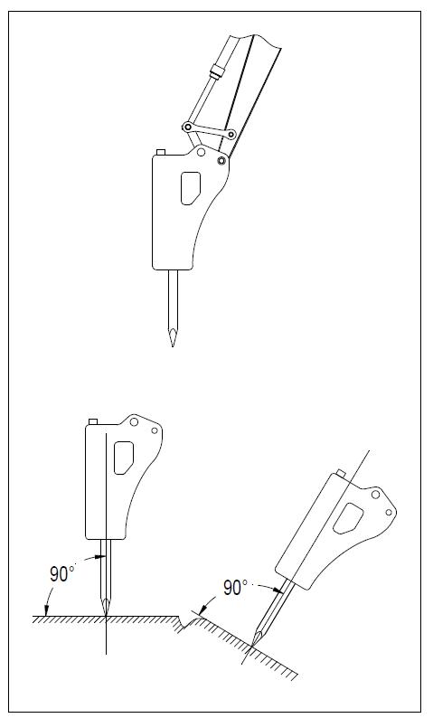
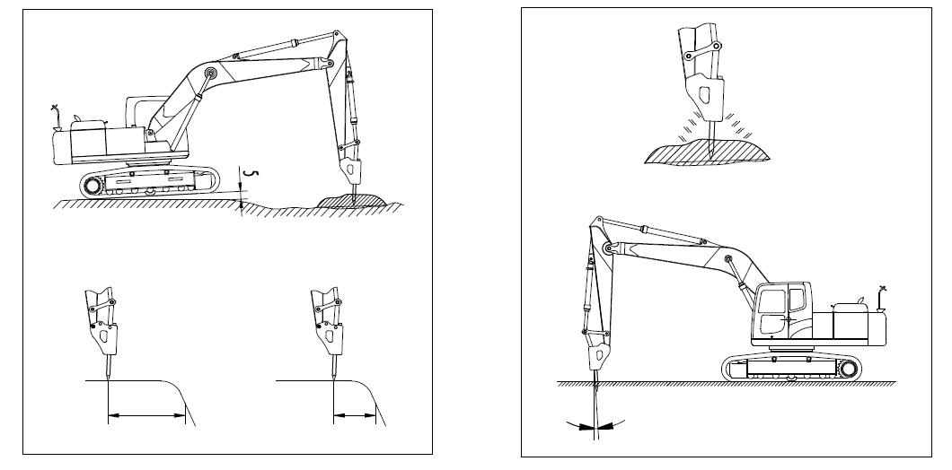
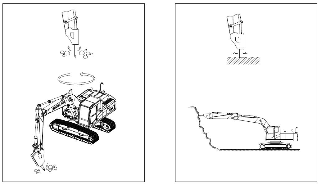
Please note the following while using a hydraulic hammer: a). During crushing operations, the chisel should be perpendicular to the impact surface (Figure 5-9). b). When the impact is applied, press the chisel down to the impact surface, so that the chassis is about 50mm (2 in) off the ground, and do not let the machine leave the ground too much c). If the chisel can not penetrate into or break the surface with continuous impact on the same surface within 1 minute, you should change the impact position to one close to the edge to break the surface (Figure 5-10). d). The penetration direction of chisel and the direction of breaker body will deviate from the straight line they were in at first. Therefore, you should keep adjusting the bucket cylinder to keep both in a straight line (Figure 5-11). e) Make sure that the chisel always appropriately imposes impact on the surface, so as to avoid applying impact when there is no resistance.
5.3.1.3 Prohibited operations
To ensure long service life and safe operation of machines, do not operate the machines in the following ways (Figure 5-12 to 5-14): a) Do not fully extend or retract the cylinders and always retain a distance of 50mm (2 in). b) Hitting rocks with the device is prohibited. c) Operation with gyroscopic force is prohibited. d) Movement of chisel during impact operation is prohibited. e) Applying impact force horizontally or upward is prohibited. f) Swinging of chisel when it penetrates the rock is prohibited. g) Pecking operation is prohibited. h) It is prohibited to raise the machine off the ground when the bucket cylinder is fully extended
5.3.1.4 Lubrication of hydraulic breaker
Lubricate the hydraulic breaker in the correct positions (Figure 5-15).
Important
If the lubrication is done at incorrect positions, excessive grease may be added and cause the earth and sand entering into the hydraulic oil circuit, and the use of breaker will damage the hydraulic device. Therefore, lubrication must be applied in the right place.
Chisel
Lubricate when the chisel pressed into the ground
Chisel
Do not lubricate when the breaking hammer body is on its side
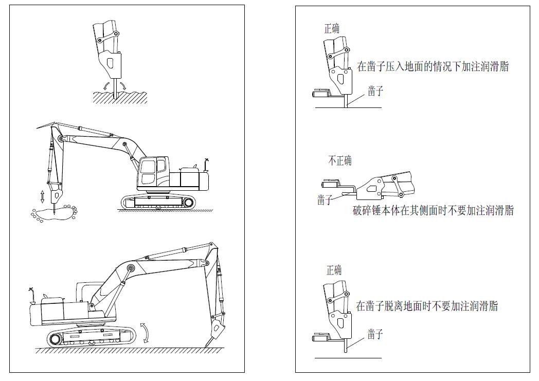
Do not lubricate when the chisel is off the ground
Chisel