36 minute read
ZE205E/ZE230E OPERATION MANUAL


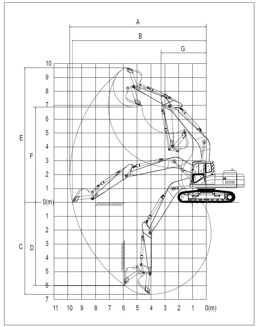
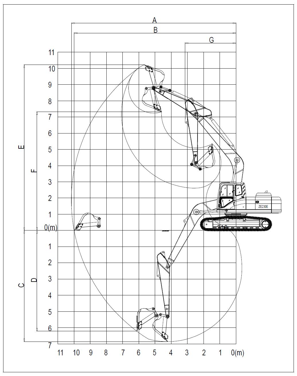
Table 2-1 ZE205E, ZE230E main technical parameter
shown in Figure 2-6)
Operation Manual
Chapter Three: Basic Operation Techniques of Excavator
Chapter Three: Basic Operation Technique of Excavator
3.1 General layout of the operating devices
Operating devices of Vanda ZE205E/ZE230E hydraulic excavators are shown in Figure 3-1.

3.2 Excavator instrument operations
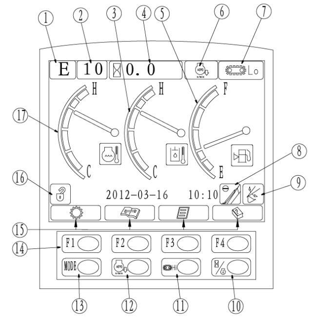
There are two kinds of instruments on the machine, which are classified as InstrumentⅠ(as shown in Figure 3-2) & InstrumentⅡ(as shown in Figure 3-34) based on difference of their working interfaces
However, each machine is equipped with only one kind. Therefore, please read the corresponding chapters as appropriate.
3.2.1 Basic operations of instrument Ⅰ
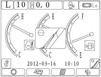
3.2.1.1 Introduction of the instrument interfaces
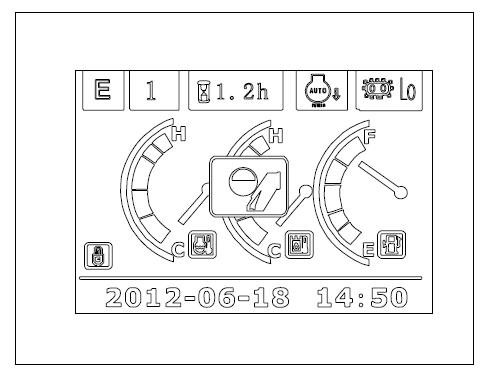
The interface is shown in Figure 3-2.
3.2.1.2 Instrument operations and settings
3.2.1.2.1 Normal startup and shut-down of the instrument
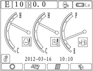
a) Startup of the instrument: turn the key switch to the ON position and the display starts to initialize into the standard interface, as shown in Figure 3-3.
Zoomlion Heavy Industry Science &Technology CO. Ltd
Welcome!
We will offer warm-hearted service to you b) Shutdown of the instrument: turn the key switch to the OFF position, the display is power-off and turns into black screen, as shown in Figure 3-4.


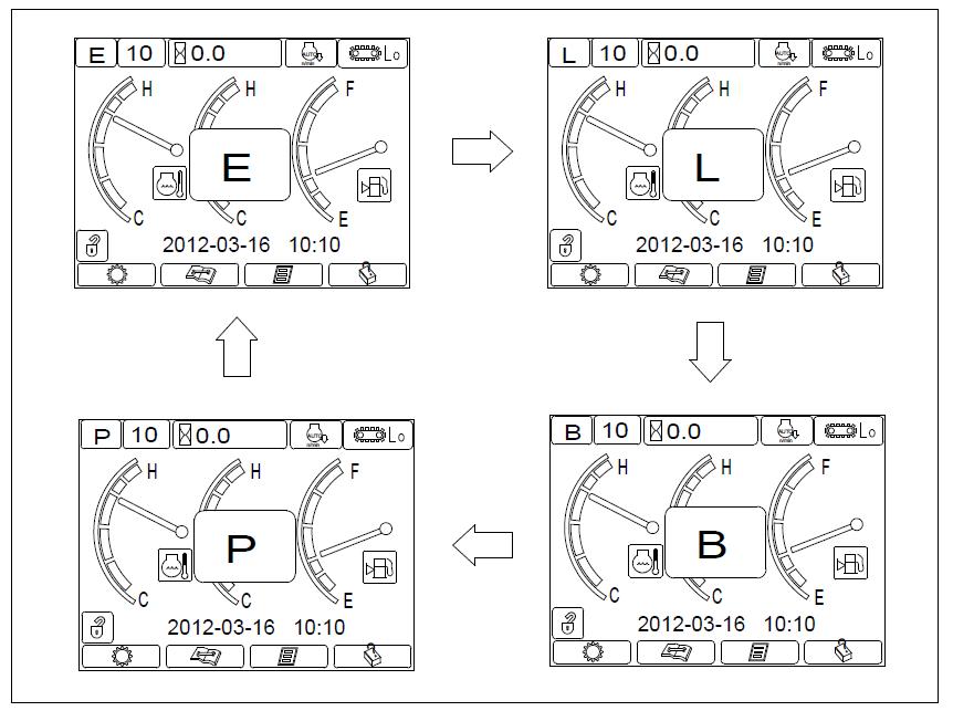
3.2.1.2.2 Selection of operating modes
Power
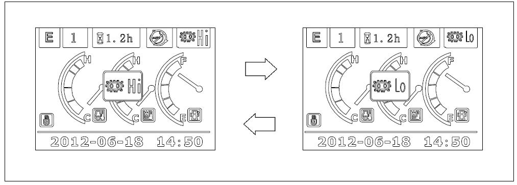
3.2.1.2.3 Traveling speed selection
When you want to change traveling speed, press the button on dashboard, Hi refers to high-speed, and L0 refers to low-speed. The power-on system default traveling speed is low speed Every time when you switch the high and low traveling speed, the corresponding mode icon will be displayed on the dot matrix LCD, and the display will return to the standard interface two seconds later, as shown in Figure 3-6.

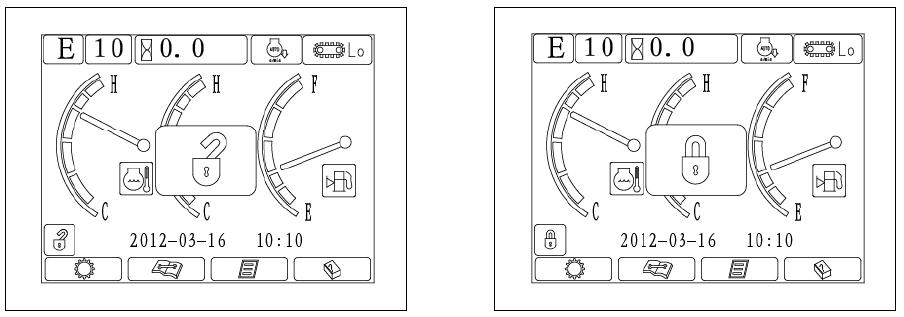
3.2.1.2.4 Pilot safety switch
Before operation, pull the safety lever up, dot-matrix LCD panel shows the unlock state and safety solenoid valve is energized, as shown in Figure 3-7. Upon completion of operations, put the safety pilot lever down and dot-matrix LCD panel shows the locked state, as shown in Figure 3-8.

3.2.1.2.5 Enable and disable automatic idling
Press the button to enable or disable automatic idling. Automatic idling is enabled by power-on system default, and then the automatic idling icon will show up on the dot matrix LCD display. When the engine speed for corresponding throttle gear is above 1350 rpm, the system controls the engine throttle and makes the engine start at 1350rpm. When the system detects that the hydraulic system is working after the machine was started, the system throttle can return to the position corresponding to the preselected throttle gear (according to the engine speed of corresponding throttle knob position in current operating mode). You can activate automatic idling function in 5 seconds delay to control the throttle and operate the engine at 1350rpm when the engine speed is more than 1350rpm and the hydraulic system does not work. When automatic idling is activated to decrease the throttle speed to 1350rpm, you cannot adjust the engine speed by adjusting the throttle knob. Press automatic idling button, the automatic idling function is canceled and the icon of automatic idling canceled will display. Press the button again to return the system default state, as shown in Figure 3-9 and 3-10.
3.2.1.2.6 Check operational parameters
Press F1 key on the standard working interface to check the system operating status, including real-time analog data, switch states and working hours collected by the controller. Menu for operating parameters is shown in Figure 3-11.

3.2.1.2.7 Time / alarm prompts
When the system sends out no alarm, current time is displayed in this area; when the system sends out alarm signal, the center of the screen shows a red alarm icon and text prompts. The menu for trouble-free condition is shown in Figure 3-12; the menu for failure condition is shown in Figure 3-13.

Each parameter alarm icon is shown in Figure 3-14.
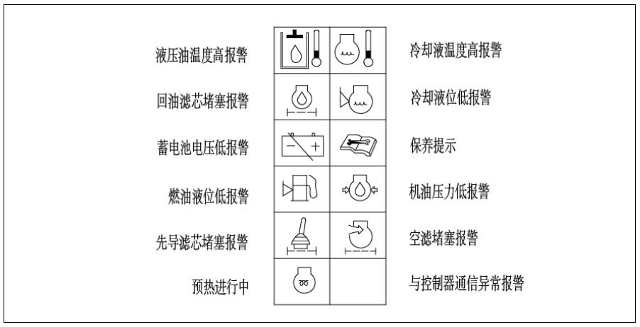
Hydraulic oil temperature too high
Oil return filter blocked
Battery voltage too low
Fuel level too low
Pilot filter blocked
Preheating
Coolant temperature too high
Coolant level too low
Maintenance prompt
Engine oil pressure too low
Air filter blocked
Abnormal communicating with the controller
3.2.1.2.8 System warming-up settings
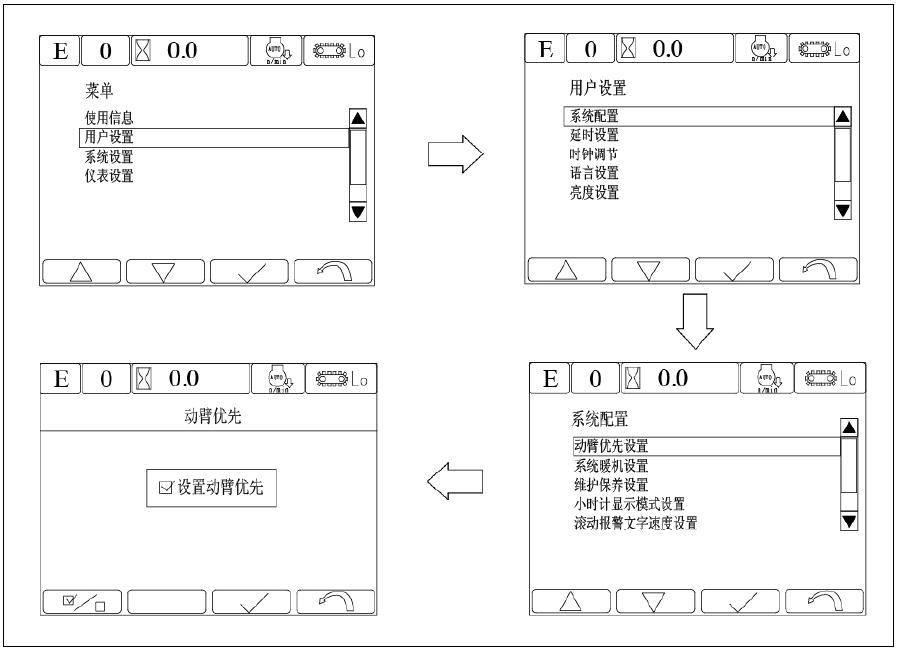
System warming-up function can be activated or deactivated via menu operations. Press F3 on the standard working interface to enter the main menu, select user settings by pressing the UP and DOWN icons F1 and F2, and press F3 to enter the user settings interface. Select system configurations via the UP and DOWN icons F1 and F2, press F3 to enter the system configurations interface, select system warming-up settings to enter the setting interface to activate or deactivate system warming-up and finally press F3 for confirmation. When this function is activated, the system begins automatic warming-up at low speed when the coolant temperature is below 10 ℃ while the engine is started and this automatic warming-up ends when the coolant temperature rises to above 30 °C. You need to select power-on system default state for this function. System warming-up setting menu is shown in Figure 3-15.
Main menu
Information for use
User setting
System setting
Instrument setting
Warming-up setting
Warming-up activated
3.2.1.2.9 Boom priority function setting
User setting
System configuration

Delay setting
Time setting
Language setting
Brightness setting
System setting
Boom priority setting
System warming-up setting
Maintenance setting
Time setting
Scrolling alarm text setting
Boom priority function can be activated or deactivated via menu operations Press F3 on the standard working interface to enter the main menu, select user settings by pressing the UP and DOWN icons F1 and F2, and press F3 to enter the user settings interface Select system configurations via the UP and DOWN icons F1 and F2, press F3 to enter the system configurations interface, select boom priority settings to enter the setting interface to activate or deactivate boom priority function and finally press F3 for confirmation. This function is activated by power-on system default state Boom priority function setting menu is shown in Figure 3-16
3.2.1.2.10 Arm semi-flow function setting
Arm semi-flow function: When the system is operating under L mode, the screen displays arm semi-flow icon and the system automatically activates this function; when the system does not work under L mode, the system automatically deactivates arm semi-flow function, as shown in Figure 3-17.
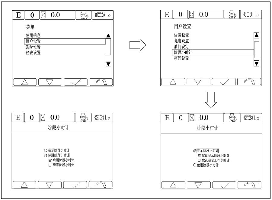
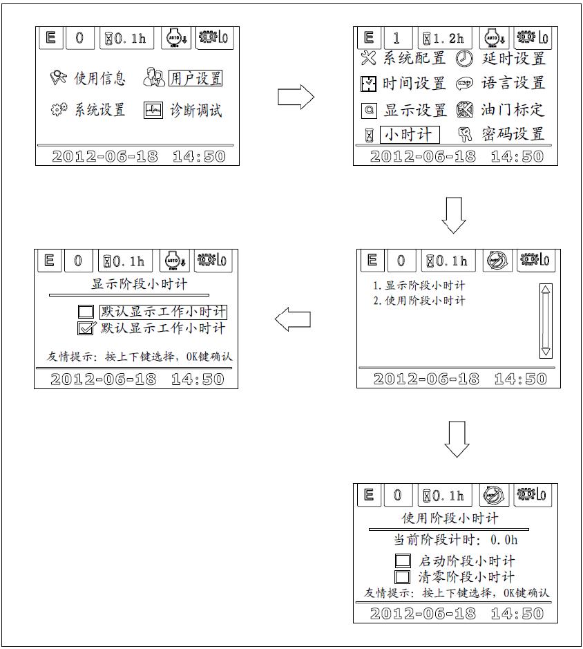
3.2.1.2.11 Period hour timing setting
Press F2 to enter period hour timing setting interface, which is for timing hours of a certain period. To check period hour timing, you can choose working hour timing or period hour timing at the main interface. As to how to use, activate or reset the period hour timing, please refer to Figure 3-18 for period hour timing setting menu
3.2.1.2.12 Check and set maintenance information
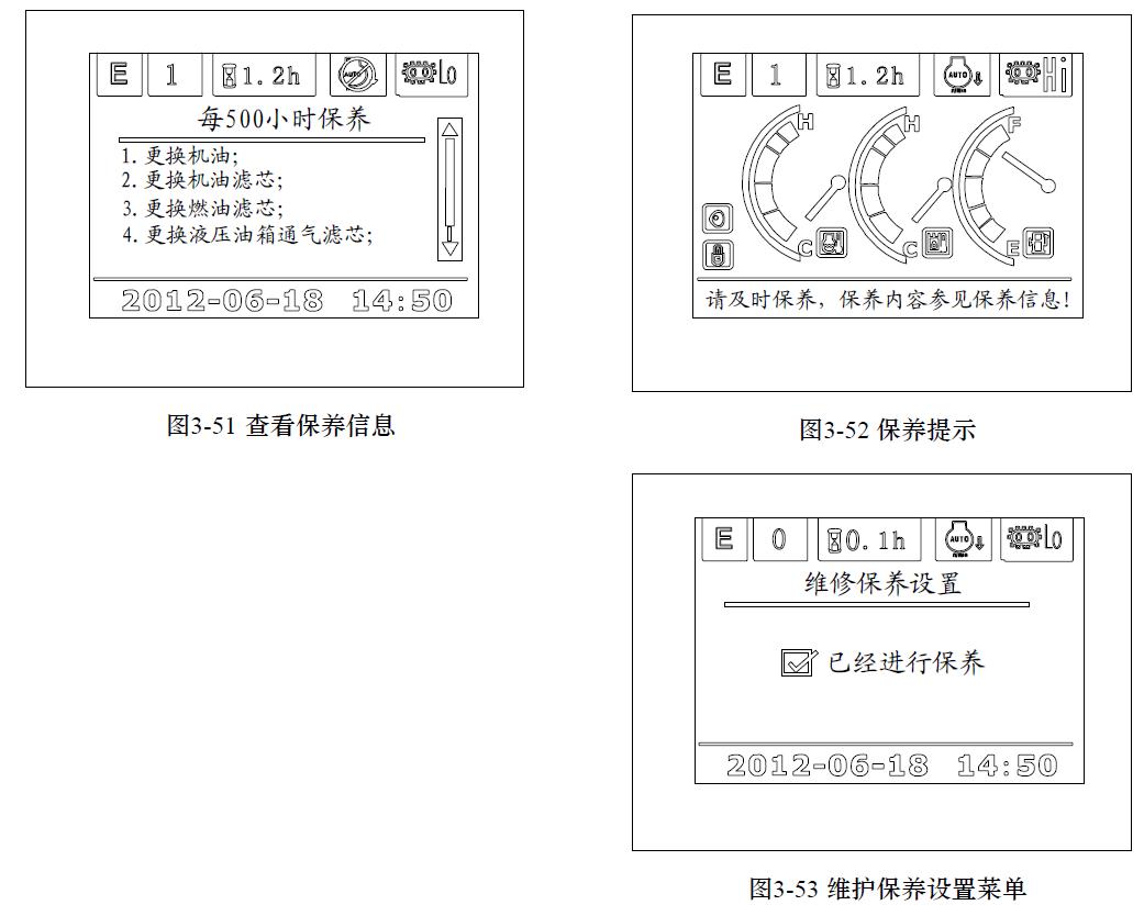
The system provides 500-hour, 1000-hour, 2000-hour and 5000-hour regular maintenance information, which is sent out 30 hours in advance You can also check this maintenance information by pressing F3. For instance, when the working hours reach 470 hours, the screen displays maintenance information as shown in Figure 3-19; when the maintenance is completed, you can enter the maintenance setting interface to set that the maintenance is completed, as shown in Figure 3-20:
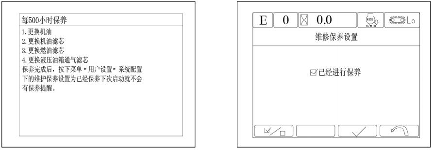
Maintenanceitemforevery500hours
1. Replace engine oil
2. Replace engine oil filter element
3. Replace fuel filter element
4. Replace hydraulic oil breather
When the maintenance is completed, press menu, user settings and system configuration in sequence to set the maintenance, so that there won’t be maintenance prompt next time when the machine is started.
3.2.1.2.13 Help / silencing
When the system sounds an alarm, press F4 key for silencing. Otherwise, press F4 for help information
3.2.1.2.14 Pressure boost switch
Only when the system power mode is under P and E mode and the engine speed is above 1650rpm, can the system perform pressure boost function. Press the button switch on the right lever, the system digging force is increased to the maximum and this function will be deactivated after 8 seconds. Moreover, this function can only be repeated after a 3-second interval. If current power mode is B mode, the system automatically switches the switch into breaker or other accessories switch. The pressure boost switch icon and the interface are shown in Figure 3-21
3.2.1.2.15 Throttle settings
When the speed of each engine gear deviates a lot from the set speed, customers can reset the throttle by entering user setting interface and selecting throttle setting.
a) Press F3 to enter throttle setting interface shown in Fig 3-22
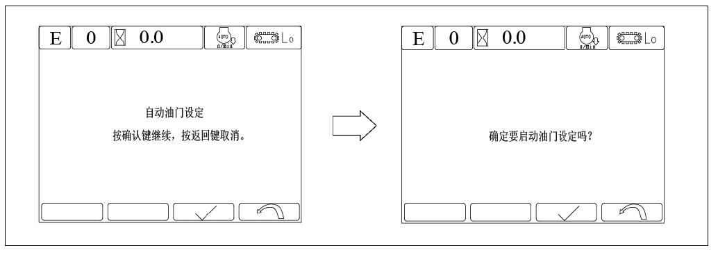

Auto throttle setting
Press confirm key to continue, return key to cancel. Start the throttle setting? b) Turn the throttle knob to max. engine speed and press F3 to confirm the adjustment. The interface is shown in Fig 3-23 c) Turn the throttle knob to min. engine speed and press F3 to confirm the adjustment. The interface is shown in Figure 3-24 d) Please start the engine: skip this if the engine has been started; the interface is shown in Figure 3-25. e) Setting interface is shown in Fig 3-26
Please turn the throttle knob to the max. engine speed and press F3 to confirm the adjustment and return to cancel.
Please turn the throttle knob to the min. engine speed and press F3 to confirm the adjustment and return to cancel.

Please start the engine Please wait.

Engine speed: 1024 Completion percentage: 10% f) Setting result is shown in Figure 3-27.

Setting completed. Press return key to return
Setting failed. Press return key to return
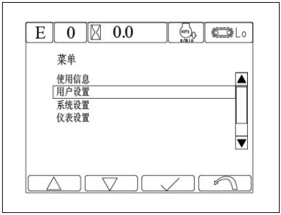
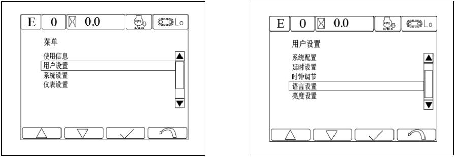
3.2.1.2.16 Time setting a) Press F3 at the standard display interface to enter into main menu, select user settings with UP and DOWN icons F1 and F2 and press F3 for confirmation; the interface is shown in Figure 3-28

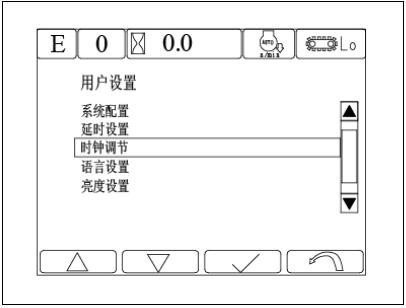
Main menu
Information for use
User setting
System setting
Instrument setting b) Press UP and DOWN icons F1 and F2 at the user setting interface to select time adjustment and press F3 for confirmation; the interface is shown in Figure 3-29

User setting
System configuration
Delay setting
Time setting
Language setting
Brightness setting c) After entering into the time settings interface, enter the exact time through F1-F4 functional keys, the interface is shown in Figure 3-30
Time setting
3.2.1.2.17 Language Selection
a) Press F3 at the standard display interface to enter into main menu, select user settings with UP and DOWN icons F1 and F2 and press F3 for confirmation; the interface is shown in Figure 3-31.
User setting
Information
User setting b) Press UP and DOWN icons F1 and F2 at the user setting interface to select language setting and press F3 for confirmation; the interface is shown in Figure 3-32 c) After entering into language setting interface, press UP and DOWN icons F1 and F2 to select the desired language and press F3 for confirmation; the interface is shown in Figure 3-33

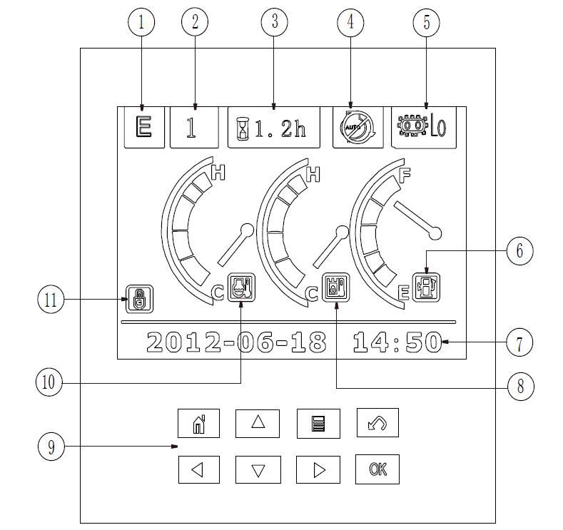
3.2.1.2.18 Pointer gauge
a) Coolant temperature pointer gauge: It indicates the current engine coolant temperature. The display range is -40 ~ 120 ℃. The yellow segment is below 40 ℃, the green segment is between 40 ~ 102 °C, and the red segment is the alarm segment. When the engine coolant temperature T is no less than 105 °C, the controller automatically controls engine throttle to downshift into a lower gear to protect the engine; if the engine coolant temperature T is no more than 95 °C, the overheating protection function is automatically canceled.
b) Hydraulic oil temperature gauge: It indicates the current hydraulic oil temperature. The display range is from -40 ~ 110 ℃. The yellow segment is below 40 ℃, the green segment is between 40 ~ 90 °C, and the red segment is the alarm segment.
c) Fuel level gauge: the display range is from 0 to 100% and the red segment is 0-10%.
3.2.2 Basic operations of instrument Ⅱ
3.2.2.1 Introduction of the instrument interfaces
The interface is shown in Figure 3-34
Standard working interfaces
Key prompt area: on the main interface worked as short-cut keys (the first row from left to right: the operating parameters, High and low traveling speed selection, main menu, help/buzzer state, the second row from left to right: Automatic idling selection , work mode, working hours/slewing speed, the period hours); on the other interfaces worked as function keys(the first row from the left to right: main interfaces, up, main menu, back; the second row from left to right: left, down, right, confirm)
3.2.2.2 Instrument operations and settings
3.2.2.2.1 Normal startup and shut-down of the instrument
a) Startup of the instrument: turn the key switch to the ON position and the display shows the standard interface, as shown in Figure 3-35 b)
Welcome!
We will offer warm-hearted service to you of
3.2.2.2.2 Selection of operating modes
Customers can choose appropriate working mode according to the operating conditions of the machine. There are P, E, L and B modes; the power-on default mode is E mode; P stands for high-power fast digging mode, E for standard economic working mode, L for light and careful digging mode, B for attachment mode like breaker. Effective adjustment range of throttle knob in each mode is as follows: P mode: 1000-2150rpm, E mode: 1000-2000rpm, L mode: 1000-1800rpm, B mode: 1000-2000rpm. Press the button to change operating mode and the instrument switching screen is shown in Figure 3-5.


3.2.2.2.3 Traveling speed selection
When you want to switch traveling speed, press the button on dashboard: Hi stands for high-speed and L0 for low-speed. The power-on system default traveling speed is low speed Every time when you switch the high and low traveling speed, the corresponding mode icon will be displayed on the dot matrix LCD, and the display will return to the standard interface two seconds later, as shown in Figure 3-38
3.2.2.2.4 Pilot safety switch

Before operation, pull the safety lever up, dot-matrix LCD panel shows the unlock state and safety solenoid valve is energized, as shown in Figure 3-39. Upon completion of operations, put the safety pilot lever down and dot-matrix LCD panel shows the locked state, as shown in Figure 3-40.


3.2.2.2.5
Press the button to enable or disable automatic idling function. Automatic idling is enabled by power-on system default, and then the automatic idling icon will show up on the dot matrix LCD display. When the engine speed for corresponding throttle gear is above 1350 rpm, the system controls the engine throttle and makes the engine start at 1350rpm. When the system detects that the hydraulic system is working after the machine was started, the system throttle can return to the position corresponding to the preselected throttle gear (according to the engine speed of corresponding throttle knob position in current operating mode). You can activate automatic idling function in 3 seconds delay to control the throttle and operate the engine at 1350rpm when the engine speed is more than 1350rpm and the hydraulic system does not work. When automatic idling is activated to decrease the throttle speed to 1350rpm, you cannot adjust the engine speed by adjusting the throttle knob. Press automatic idling button, the automatic idling function is canceled and the icon of automatic idling canceled will display. Press the button again to return the system default state, as shown in Figure 3-41 and 3-42.
3.2.2.2.6 Check the operational parameters
Press the button on the standard working interface to check the system operating status, including real-time analog data, switch states and working hours collected by the controller. Menu for operating parameters is shown in Figure 3-11.
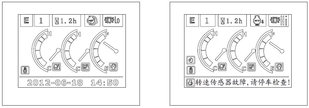

3.2.2.2.7 Time / alarm prompts
When the system sends out no alarm, current time is displayed in this area; when the system sends out alarm signal, the center of the screen shows a red alarm icon and text prompts, as well as buzzer icon shown at the upper-left of the prompt frame (press to startup or shutdown the buzzer). The menu for trouble-free condition is shown in Figure 3-44; the menu for failure condition is shown in Figure 3-45.
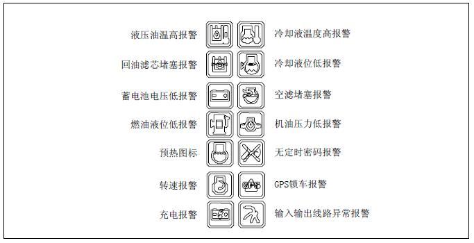
Each parameter alarm icon is shown in Figure 3-46.
Hydraulic oil temperature too high
Filter blocked
Battery voltage too low
Fuel level too low
Preheating Slewing speed Recharging
Coolant temperature too high
Coolant level too low
Air filter blocked
Engine oil pressure low
No timing-password
GPS machine-locking
Abnormal input & output circuits
Figure 3-46 Each parameter alarm icon
3.2.2.2.8 System warming-up settings
System warming-up function can be activated or deactivated via menu operations Press on the standard interface to enter the main menu, select User settings by pressing the UP and DOWN buttons and
System heater setting
Heater started
Warm reminding: OK for confirm
Boom priority setting
Arm semi-flow setting
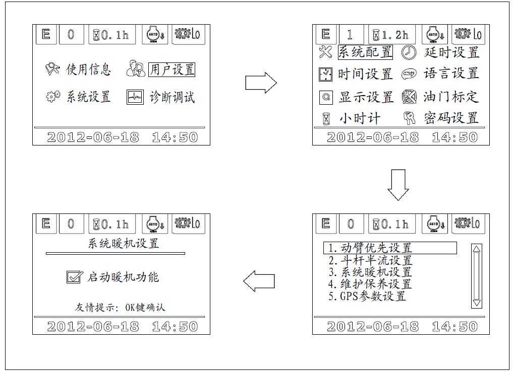
System heater setting
Maintenance setting
GPS parameters setting press OK button to enter the user settings interface, select the system configuration via the UP and DOWN keys, then press OK button to confirm and enter the system configuration interface, select system warming-up setting to enter the setting interface to activate or deactivate system warming-up, and finally press OK for confirmation When this function is activated the system begins automatic warming-up at low speed when the coolant temperature is below 10 ℃ while the engine is started and this automatic warming-up ends when the coolant temperature rises to above 30 °C. You need to select power-on system default state for this function. System warming-up setting menu is shown in Figure 3-47.
3.2.2.2.9 Boom priority function settings
Boom priority function can be activated or deactivated via menu operations Press on the standard interface to enter the main menu, select User settings by pressing the UP and DOWN buttons and press OK button to enter the user settings interface, select the system configuration via the UP and DOWN keys, then press OK button for confirmation and enter the system configuration interface, select boom priority setting to enter the setting interface to activate or deactivate boom priority, and finally press OK for confirmation.This function is activated by power-on system default state Boom priority function setting menu is shown in Figure 3-48
3.2.2.2.10 Arm semi-flow function settings

Arm semi-flow function: When the system is operating under L mode, the screen displays the arm semi-flow icon and the system will automatically activate this function; when the system does not work under L mode the system will automatically deactivate the arm semi-flow function, as shown in Figure 3-49
3.2.2.2.11 Period hour timing setting
Period hour timing function can be activated or deactivated via operating the menu key. Press the button on the standard interface, select the User setting via the UP and DOWN keys, and press OK to enter the user setting interface, then select the hour timing set by the UP and DOWN keys, then press OK to confirm and enter into the hour timing interface to activate or deactivate the function and then press OK to confirm. Setting menu is shown in Figure 3-50.
3.2.2.2.12 Check and set maintenance information
The system provides 500-hour, 1000-hour, 2000-hour and 5000-hour regular maintenance information, which is sent out 30 hours in advance. You can also check the maintenance information by pressing the button, as shown in Figure3-51. For instance, when working hours reach 470 hours, the screen displays the self test prompt at power on, as shown in Figure 3-52: when maintenance is completed, you can enter the maintenance setting interface to set that the maintenance is completed, as shown in Figure 3-53
Every 500 hours’maintenance
1. Replace engine oil
2. Replace engine oil filter element
3. Replace fuel filter element
4. Replace hydraulic oil ventilation filter element
3.2.2.2.13 Pressure Boost switch
Maintenance setting
Maintenance is completed
Only when the system power mode is under P and E mode and the engine speed is above 1650rpm, can the system perform pressure boost function. Press the button switch on the right lever, the system digging force is increased to the maximum and this function will be deactivated after 8 seconds. Moreover, this function can only be repeated after a 3-second interval. If current power mode is B mode, the system automatically switches the switch into breaker or other accessories switch The pressure boost switch icon and the interface are shown in Figure 3-54.

3.2.2.2.14 Help / silencing
When the system sounds an alarm, press for silencing, otherwise, for help information. The help information covers order operation prompt, instructions for using timing, control and maintenance of throttle and contacts.
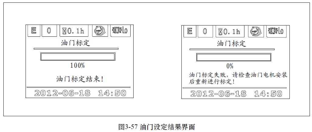
3.2.2.2.15 Throttle setting
When the speed of each gear deviates a lot from the set speed, customers can reset the throttle by entering user setting interface and selecting the throttle adjustment setting.
a) Press OK to confirm whether entering the throttle setting, the interface is shown in Figure 3-55 b) Throttle adjustment is setting, as shown in Figure 3-56
Throttle setting
Conducts throttle setting?
Throttle setting
Make sure the engine was started before calibration
Make sure the engine was started before setting c) Throttle setting completed, as shown in Figure 3-57.
Throttle setting
Don’t do other operations when conducting the throttle setting
Throttle setting completed
3.2.2.2.16 Time setting
Throttle setting
Throttle setting failed, please check the throttle electric equipment and repeat setting a) Press at the standard interface to enter main menu, select user settings with

UP and DOWN icons and then confirm, the interface is shown in Figure 3-58 b) Select time setting via UP and DOWN icons under the user setting interface and then press OK to confirm, the interface is shown in Figure 3-59 c)After entering the timing setting interface, enter the exact time through the UP and DOWN icons, the interface is shown in Figure 3-60


3.2.2.2.17
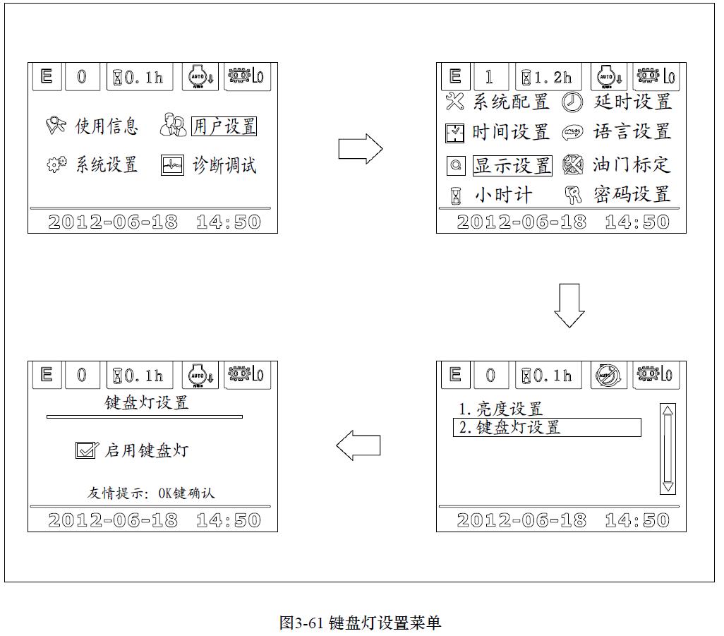
Keyboard light can be activated or deactivated both automatically according to the month and the system time and selectively via the buttons on the order. when the keyboard light function is started, all the keys display green a)Time table for the keyboard light automatic turn-on or turn-off according to the month and system time, As shown in Table 3-1. b) Select keyboard light turn-on or turn-off via the menu keys. Press on the standard display interface to enter the main interface, select the user menu by direction keys and press OK to confirm, then you can choose display setting under the user setting interface and press OK to enter display setting interface to start keyboard light function, as shown in Figure 3-61
3.2.2.2.18 Pointer gauge a) Coolant temperature gauge: It indicates the current engine coolant temperature. The display range is -40 ~ 120 ℃. The yellow segment is below 40 ℃, the green segment is between 40 ~ 102 °C, and the red segment is the alarm segment. When the engine coolant temperature T is no less than 105 °C, the controller automatically controls engine throttle to downshift into a lower gear to protect the engine; if the engine coolant temperature T is no more than 95 °C, the overheating protection function is automatically canceled. b) Hydraulic oil temperature gauge: It indicates the current hydraulic oil temperature. The display range is from -40 ~ 110 ℃. The yellow segment is below 40 ℃, the green segment is between 40 ~ 90 °C, the red segment is the alarm segment. c) Fuel level gauge: display range is from 0 to 100%,and the red segment is 0 to 10%.
3 Basic operating instructions
3.3.1 The basic checking items
Warning a) Coolant low-level alarm
1. You cannot completely rely on the monitor to determine the machine’s status. While doing daily checks before startup, you should get off from the machine and conduct direct checks for all items instead of simply relying on the monitor.
Before starting the engine, you must check two basic items: coolant low-level alarm and maintenance prompts. If there are any abnormalities, corresponding instruments will go on and the buzzer will sound.
This indicator warns the operator that the coolant level in this radiator has dropped. If coolant level in this radiator is too low, the light turns red. Then you should check the coolant levels in this radiator and auxiliary tank and add water, as shown in Figure 3-62.

b) Maintenance prompts indicator
Maintenance prompt indicator is a warning light to remind the operator that the set time since the last maintenance is up, as shown in Figure 3-63
This warning stops and returns to normal operation status after 5 seconds. If the maintenance is completed, you can press the "OK" button on the screen, indicating that the maintenance is completed.
If you need to change the setting of maintenance period, please contact Zoomlion or Zoomlion dealer.
c) Charge indicator
Battery voltage alarm warns the operating personnel that there is charging abnormalities while the engine is running. If the battery did not properly charged when the engine is running, the corresponding alarm icon will go on, along with text prompts, as shown in Figure 3-64 d) Fuel level too low alarm
When this alarm light is on, the operator is warned that the fuel level is too low, the fuel left can only support the machines to work for 1 to 2 hours and he should add fuel as soon as possible, as shown in e) Air filter blocked
Figure3-65.
When this alarm light is on, the operator is warned that the air filter is blocked, as shown in Figure 3-38
Turn off the engine, and check and clean the air filter.
Warning
1. If the indicator turns red, immediately turn off the engine or keep it running at low idle speed, then check corresponding parts and take necessary actions a) Coolant temperature alarm
When the engine is running, you should pay particular attention to these items. In case of any abnormalities, the indicators corresponding to abnormal parts will turn red, and the buzzer will sound, so immediate action should be taken.

The coolant temperature alarm warns that the coolant temperature is too high.
If the engine coolant temperature becomes abnormally high, the warning light turns red, overheating prevention system automatically starts and the engine speed drops, as shown in Figure 3-67 b) Hydraulic oil temperature alarm
If necessary, stop the operation and keep the engine running at low idle speed until the warning light is black out.
The hydraulic oil temperature alarm warns the operator of increased hydraulic oil temperatures. If the warning light turns red during operation, run the engine at low idle or shut down the engine until the oil temperature drops and the warning light goes out, as shown in Figure 3-68 c) Engine oil pressure alarm
If the engine lubricating oil pressure falls below normal level, this alarm light turns red. Then turn off the engine and check the lubrication system, as well as the oil level in the sump, as shown in Figure 3-69


Note: This indicator will be on when the starter switch is turned to ON position and it goes off as long as the engine is started. It is normal that the buzzer sounds temporarily when the engine is being started.
3.3.3 Basic operations of switches
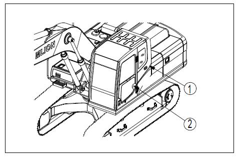
Locations of switches are shown in Figure 3-70
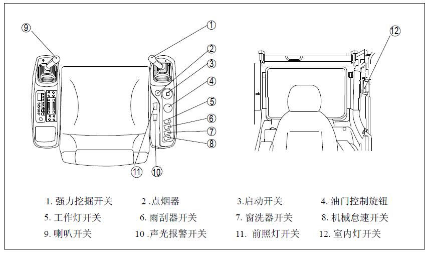
Powerful digging switch
The powerful digging switch (1) on the top of the right lever shown in Figure 3-71 is increasing digging force. Press the switch and the powerful digging icon at the upper area of the display will show the weightlifter lifting the barbell. Under P or E mode and when the speed is greater than 1650 rpm, the machine can function at maximum power for 8 seconds. After that, the hydraulic pressure and engine speed return to normal.
1. The interval between two powerful digging operations should be at least three seconds and only a maximum of three powerful digging operations are allowed within one minute.
3.3.3.2 Cigarette lighter
Light cigarettes with the switch (2) shown in Figure 3-72. When being pushed in, the cigarette lighter will return to its original position a few seconds later; pull it out and it is ready for use. If the cigarette lighter is removed, it turns into a power outlet (The maximum bearing power is 85W). The power of the cigarette lighter is 85W (24V x 3.5A).
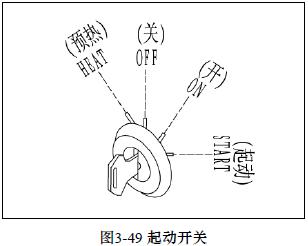
3.3.3.3 Starter switch
The starter switch (3) is used to start or shut down the engine as shown in Figure 3-73
OFF position: You can insert or remove the key.
ON position: the electrical system connects to power. When the engine is running, make sure the starter switch key remains at the ON position.
START position: This is the engine start position. When starting the engine, the key is at this position. After the start of the engine, release the key immediately, and it will automatically return to the ON position.
1. The pilot safety locking lever must be locked when starting the engine, turn the starter switch to the START position. and if the engine fails to start after 10 seconds, please wait for another 2 minutes to restart the engine. If the starting of the engine continues for more than 15 seconds, the starter may burn out.


3.3.3.4 Throttle control knob
The control knob (4) is used to control the engine speed and power output, as shown in Figure 3-74.
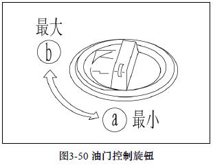
a) Low idle position: turn this knob left (counterclockwise) b) High idle position: turn this knob right (clockwise)
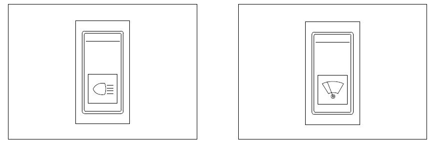
3.3.3.5 Work lights switch
The switch (5) shown in Figure 3-70 (5) is used to control the headlights and boom lights. The switch works at three positions: a) All lights are off b) Boom is on c) Both lights are on
3.3.3.6 Wiper switch
The wiper switch (6) shown in Figure 3-48 is used to control the activation and speed of the wiper.
The switch works at three positions: a) The wiper is off b) The wiper works slowly. c) The wiper works quickly
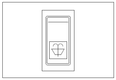
3.3.3.7 Window washer switch
You need to spray water on the glass during cleaning The window washer switch (7) shown in Figure 3-77 is used to control the activation and speed of the washer. The switch only works at ON and OFF positions.
3.3.3.8 Idle switch
When the left and right control levers as well as the traveling lever are in the neutral positions, press the switch (8) shown in Figure 3-78, and the control system reduces the engine speed to the minimum and the instrument displays the idle icon and text prompts. The idle function will be automatically canceled when the left or right control lever or the traveling lever moves


3.3.3.9 Emergency mode switch
When the controller can not work properly, pull the emergency mode switch (as shown in Fig 3-79) to the emergency position to control the main pump proportional solenoid to output a constant current
Switch (10) shown in Figure3-70 is used to control the on-off of the sound and light alarm, as shown in Figure 3-80.
3.3.3.11 Headlamp switch
Switch (11) shown in Figure 3-70 is used to turn on the two headlamps, and the icon is corresponding to the work light, shown in Figure 3-75.
3.3.3.12 Interior light switch
The switch (12) shown in Figure3-70 is used to open the interior lights. ON position: light on; OFF position: Light off. Please see Figure 3-81

3.3.3.13 Horn switch
When you press switch button (9 )at the top of left lever, the horn sounds, as shown in Figure 3-82.
3.3.4 Instructions of the control devices
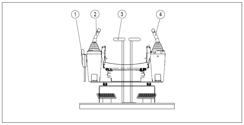
Layout of each control devices is shown in Figure 3-83.
2 Left lever
3.3.4.1 Safety locking lever
4 Right
1. When leaving the cab, the safety locking lever must be firmly placed in the locked position, as shown in Figure 3-84. If not, serious personal injury may be caused when the lever is moved by mistake.
2. If the safety locking lever is not securely placed in the locked position, the lever may be moved, resulting in a serious accident or injury.
Pay attention not to touch the lever for working device when pulling the safety locking lever up.
Pay attention not to touch the lever for working device when pushing the safety locking lever down
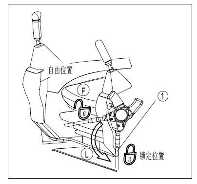
The lever ① is a device for locking working device, slewing, traveling and accessories (if any). Pull the lever up to lock the device.
The locking lever is of hydraulic lock type, so even if it is in the locked position, the levers for working devices and the traveling lever can still be moved, but the working device, traveling motor and slewing motor will not work.
3.3.4.2 The use of lever
3.3.4.2.1 Lever for working device
Changes of the automatic idle function of engine are as follows: a) When the traveling lever and the levers for working device are in the neutral positions, the engine speed will be reduced to idle even if the fuel control knob is at a speed above the medium-speed. Operating of either one of the levers will raise the engine speed to the speed set by the fuel control knob. b) If all levers are in the neutral positions, the engine speed will be reduced down to the set speed of the automatic idle speed (about 1350rpm) after about 5 seconds. c) The left lever ② shown in Figure 3-83 and Figure 3-85 is used to control the bucket arm and the slewing of superstructure a) Arm unloading b) Arm digging c) Slew to right d) Slew to left d) The right lever ④shown in Figure 3-54 and 3-57 is used to operate the boom and bucket.
N (neutral position): the superstructure and the arm remain fixed in place.


Operation of boom / bucket: a) Raise the boom b) Lower the boom c) Bucket unloading d) Bucket digging
N (neutral position): boom and bucket remain fixed in place.
3.3.4.2.2 Traveling lever
1. Unless the machine is traveling, do not step your feet on the pedal, if your feet stays on the pedal and depresses it by mistake, the machine will move suddenly and may cause a serious accident.
2.When the track frame faces backward, the machine moves in reversing direction in way of traveling forward and forward direction in way of reverse traveling.
3. Check if the track frame faces forward or backward before using the traveling lever. (If the sprocket is in the rear, the crawler frame faces forward.)
4. When pedal is used for controlling operation and traveling, particular attention should be paid.
The lever ③ shown in Figure 3-83 is used to change the machine’s traveling direction (when the front of the superstructure is in the same direction with the idler), as shown in Figure 3-87. The following is the description for pedal operation.
(a) Traveling forward: move the lever forward (tilt the pedal forward)

(b) Reverse: move the lever backward (tilt the pedal backward)
(c) N (neutral): the machine stops
3.4 Cab accessories operating instructions
3.4.1 Ashtray
The ashtray is in the right front side of the cab Be sure to put out the cigarette before putting it into the astray and then close the lid.
3.4.2 Air conditioner
3.4.2.1 Precautions for using the air conditioner
1. The air conditioner should be started when the engine is running at low speed. Do not start the air conditioner when the engine is running at high speed, for this will cause damage to the air conditioner.
2. If water enters into the control panel of the A/C, accidental failures may occur. Therefore, be careful not to allow water to enter into these parts. Besides, do not expose these parts to open flame.
a) When using the A/C, the cab should be kept ventilated:
Smoking when the A/C is on is bad for eyes, so you should open the window for ventilation and activate the cooling system of A/C for a while to exclude the smoke
When the A/C has run for a long time, ventilate the cab and activate the cooling system of A/C once per hour.
b) Fog on windows:
In rainy or humid days, if fog appears at the inner side of the window, open the air conditioner to help keep the window clear. Excessive use of air conditioner in very humid air may cause fogging at the outerside of the window. At this time, you should turn off the air conditioner to regulate the temperature of the cab.
1. Be careful not to set the cab temperature too low. When the cooler is on, set the temperature to one that is 5-6 °C lower than the outdoor temperature. This temperature is considered to be the most suitable for human body. So pay attention to properly regulate the temperature.

3.4.2.2 Button description
The air conditioner should be turned off when the engine gets started; the air-conditioning control panel equipped in the machine is shown in Figure 3-88
1.
Switch (1) is a group of air regulator or ventilation selection switch as shown in Figure 3-89. There are four modes:
: Bottom ventilation, ie, wind comes out from vent C.
: Bottom and rear ventilation: wind comes out from vents A and C at the same time.
: Rear ventilation: wind comes out from vent A.
: Defrosting: bottom and front air vents are opened
(A): Rear vents (4)
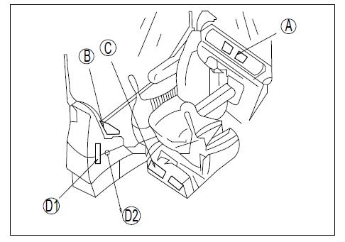
(B): Front vent (1)
(C): Bottom vent (1)
(D1): Front window vent (1)
(D2): Front window vent (1)
Description:
The front window vent (D2) can be turned on or off by hand.
2. Temperature control switch:
The switch (2) is used to control the temperature of the cab. There are 12 grades of temperature available for adjustment, with red for heating and blue for cooling.
Tip: While heating, A/C is in closed state and corresponding indicators are off, while cooling, A/C must be on and corresponding indicators are on
Press the switch to increase the set temperature. Press the switch to decrease the set temperature.
3. Air volume control switch:
The air volume control switch (3) is used to adjust air flow among four grades, namely low, middle 1, middle 2 and high.
Press the switch to increase the set air volume. Press the switch to reduce the set air volume.
4. Fresh / cycle selective switch:
The switch (4) is used to switch between interior air recirculation and outdoor air inlet.
: Fresh air inlet: This switch is used for outdoor air inlet or defrosting.
: Outdoor air is cut off and only interior air circulation is activated. Use this switch for rapid cooling of the cab or when the outdoor air is not clean.
5. ON/OFF switch:
The switch (5) controls the on or off state of the A/C.
6. A/C cooling switch:
Turn on the switch (6) for cooling and the compressor is started. Turn off this switch for heating and the compressor stops working. Generally, the temperature adjustment switch is used for cooling among grades
2-5 and for heating among grades 6-11
3.4.2.3 A/C operating instructions
3.4.2.3.1
Panel operation
a) Press the air volume control switch ③ to adjust the air flow to the required grade b) Turn on the A/C switch ⑥for cooling and turn off the A/C switch ⑥ for heating; check whether the indicator light on the A/C switch is on. c) Press the temperature control switch ② to adjust the cab temperature to a moderate one. d) Press the Mode switch 1 to select the required ventilation mode. For the mode chosen, the indicator light on corresponding switch will be on e) Press the fresh / cycle selective switch ④ to select the cab interior air circulation or outdoor fresh air inlet f) Press the ON / OFF switch ⑤, and the display for temperature setting and air volume setting as well as the indicator light on the A/C switch all go out and the operation stops.
3.4.2.3.2 Operation of the defroster
a) Press the air volume control switch ③ to adjust the air volume b) Press the defrosting mode switch among mode switches ① c) Press the fresh / cycle selective switch ④ to select fresh air inlet mode. d) Press the temperature control switch ② to adjust the set temperature to the hottest one e) selective switch ④ to select fresh air inlet mode
3.4.3
Motor
radio
3.4.3.1 Function control and instructions:
The radio control panel of the machine is shown in Figure 3-90:
1 Power / source control keys
3 LCD screen
2. Automatic radio store & band selection key

4. Volume control keys
5. Radio preset / MP3 player control function keys
(Note: PAU-Pause; SCN-Scan; RPT-Repeat; RDMs-Random)
6. Manual Tuning
7. Clock & sound set selection key
8. Mute & loud key 9.USB interface
3.4.3.2 Precautions for use
a). To avoid accidents, please select the appropriate volume.
b). The radio get damaged easily if being splashed wet, so please pay attention not to let water spray into the radio when you have the machine washed.
c). The default button settings will have been eliminated when replacing the battery, these settings should be reset.
3.4.3.3 Radio Operating Instructions:
a). Power on / off b). Automatic radio search and store long press the key "2" for automatic channel search from the low-limit frequency, and the radios searched will be sequentially stored in preset stations 1-6; Short press the key "2" is to switch between FM and AM. c). Volume Control
Press the key "①" to turn on the radio, long press to cut off the radio power.
Press the key “④ + ” to increase the volume gradually; press the key "④ -", to reduce the volume gradually d). Select a preset station
Press any number key in "⑤" to select corresponding preset radio; e). Band selection key
During playing, long press any number key in “⑤” to save the current frequency into corresponding preset station.
Press the key "⑥" for forward / backward search, which can be either automatic search or manual search..
Automatic station search: Press the key “⑥ → / ⑥ ←” for forward / backward search; the radio stops searching to play when a station is searched.
Manual search: Press the key “⑥ → / ⑥ ←” to enter manual search. Hold the key pressed and the frequency moves forward / backward quickly; release the button and the frequency stops beating, but you can still short press the key “⑥ → / ⑥ ←”to gradually adjust the frequency. If the button is not pressed within 2 seconds, the radio will exit from manual search mode and return to automatic search mode f). Sound settings
Short press the key "⑦" to check the clock and you can press this key again within two seconds to enter into sound setting mode. If no button is pressed within 2 seconds under clock display mode and sound setting mode, the radio will exit from clock display mode and return to radio frequency display mode.
Under clock display mode, press and hold the key "⑦",to enter clock adjustment.
For sound settings, each time you press the key, you can select VOL-> BAS-> TRE-> BAL-> VOL in return and then you can press the key "④+ /④-" to adjust the volume accordingly: bass, treble, balance, etc.
Note: VOL-volume BAS-bass TRE-treble BAL-balance g). Mute and sound control
Short press the key "⑧", the radio will be mute; press it again to release the mute state. Mute symbol is displayed on the LCD screen. Adjusting the volume under mute mode will also release mute state
Long press the key "⑧", the loudness mode will be activated; press it again to release the loudness state
A "LOUD" symbol is displayed on the LCD screen.
3.4.3.4 MP3 operating instructions
a). Short press the key <SOURCE> to select MP3 player.
b). Firstly the radio will read U disk player c). After U disk is read, it first shows the total number of tracks, and then starts playing. d) Play at breakpoint
For no U disk, it shows "NO DISC".
If there is U disk with no MP3 files, then it displays "NO SONG".
If the radio was shut down or switched to radio station while the MP3 was playing, next time the MP3 will start playing from where it was last played if the U disk last played does not change
If there is only U disk and it was unplugged while playing, the radio will start playing from where it was last played when the device is inserted again if the MP3 songs on it remain unchanged e). While playing, LCD screen displays the track number and the play time of the current track. f) Pause g) Song selections h) Quick song selections i). Repeat, random and play
Press the button <1/PAUSE> during playing to pause, and the track number and play time will flash on the LCD screen; press it again to continue playing.
Press the key “⑥ → / ⑥ ←” for forward / backward song selections.
Press and hold the key "⑥ → / ⑥ ←" to quickly increase or decrease the track number. When the key is released, you can still press it to adjust the track number one by one. If the button isn’t pressed within one second, the radio skips to the track last selected to play.
Press one of <3/REPT>, <4/RAND> and <2/SCN> keys to select corresponding play mode. Press that button again and the songs will be played in sequence j). Supported MP3 song types
MPEG 1/2/2.5 Layer 3 Audio
Sampling frequency: 8k, 11.025k, 12k, 16k, 22.05k, 24k, 32k, 44.1k and 48k
Bit rate: 32Kbps-320Kbps, VBR supported
As for the number of MP3 files on the U-disk, the system only supports up to 511 MP3 files for each device and the excessive files will not be played by the system.
3.4.4 Antenna
Before transporting the machine or placing it inside a building, the antenna should be withdrawn in order to prevent any interference.
3.4.5 Windows and locks
3.4.5.1 Skylight
1. When you leave the cab, the safety locking lever should be firmly placed in the locked position, as shown in Figure 3-84.
2. If the lever hasn’t been locked, it may be touched by mistake and result in serious accidents.
a). When opening the window:
Firmly lock the safety locking lever
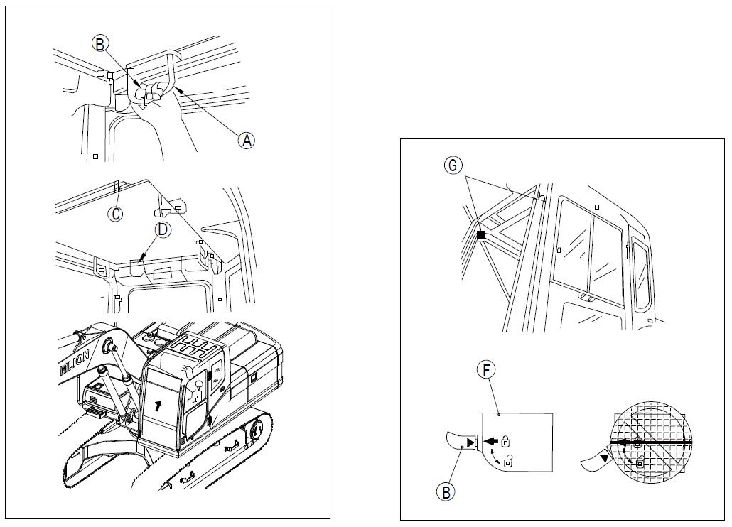
Pull the front handle lock knob (1), check whether the skylight is movable and then release the handle (1) to let the skylight open up under the force of the two gas springs at both sides (2), as shown in Figure 3-91 b). When closing the window:
Hold the handle (1) to close the skylight and lock it with the handle lock knob (1). If it is not locked up, open it once again and close.
3.4.5.2 Front window
1. When opening or closing the skylight, front window, rear window or door, the safety locking lever should be placed in the locked position.
2. If the lever wasn't locked and it was accidentally touched, serious accidents will occur.
3. Before opening or closing the front window of the cab, the machine should be parked on level ground, the working device should be completely lowered to the ground and the engine should be shut down.
4. While opening the front window, hold the handle firmly with both hands, pull it up and do not let it go until the automatic lock gets locked.
5. While closing the front window, the window will move fast under its own weight, so when you are closing the front window, you should hold the handle firmly with both hands
3.4.5.2.1 Opening steps
The front window (upper part) can be placed (pulled up) at the top of the cab, as shown in Figure 3-92. The opening steps are as follows: a) Lower the working device to level ground and stop the machine. b). Firmly lock the safety locking lever c). Check whether the wipers blades are retracted in the right box. d). Hold the handles (A) of the front window and pull the handle lock knob (B) to open the lock of the top of the front window, as shown in Figure 3-93. The top of the front window will then be pulled out. e). Hold the bottom handle (C) inside the cab with the left hand and hold the top handle (D) with the right hand to pull the front window up and remove it. f). Check whether the handle lock (B) is firmly located in the locked position.


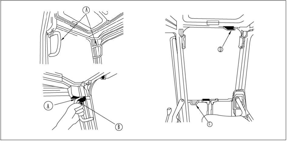
If the arrow on lock shell (F) is directly facing the arrow on the lock handle (B), the handle is well locked, as shown in Figure 3-94. If the arrow on lock shell (F) is not facing the arrow on the lock handle (B), the handle hasn’t been locked; repeat step 5 to lock it.

3.4.5.2.2 Closing steps
Warning
1. When closing the front window, slowly put the front window down and be careful not to nip your hand.
Closing steps are as follows: a). Place the working device on a flat ground and turn off the engine. b). Firmly lock the safety locking lever c). Hold the left and right handles (A) and pull the handle (B) down to release the lock as shown in Figure 3-95 d). Hold the handle (C) at the bottom of the front window with the left hand and the handle (D) at the top with the right hand, push the window forward, and then slowly put it down e). When the bottom of the window gets close to the top of the lower window, you should push the bottom of the window forward, so that the front window couples the left and right locking pins (G) and gets locked. f). Check whether the lock handle (B) is firmly located in the locked position.
If the arrow on lock shell (F) is directly facing the arrow on the lock handle (B), the handle is well locked, as shown in Figure 3- 96 If the arrow on lock shell (F) is not facing the arrow on the lock handle (B), the handle hasn’t been locked; repeat step 5 to lock it.
3.4.5.3 Lock
3.4.5.3.1 Door lock
When the door is opened, use the door lock as shown in Figure 3-97 to fix the door in place (1).
a). Push the door to the direction of the lock pin (1) to fix the door in place.
b). When opening the lock, press the button (2)at the left side of the driver's seat to open the lock pin.
c). Fix the door firmly to the lock pin.
3.4.5.3.2 Caps and covers with locks
Locks are fixed at the injection ports of the fuel tank and hydraulic oil tank, driver’s cab, engine cover, battery cover as well as left and right doors of the machine. These caps, doors and covers can be opened by keys The keys should be fully inserted to the end before being turned, otherwise it may break
The steps for opening and locking the caps with locks: a) For opening: b) For locking
1). Insert the key into the key slot.
2). Turn the key counterclockwise, align the key slot with the mark on the cap and then open it.
1). Screw the cap on and then insert the key into the key slot
2) Turn the key clockwise as shown in Figure 3-98 and then remove the key.
3.4.5.3.3 Methods for opening and locking covers with locks
a) Open the cover (locked cover): b) Lock the cover:
1). Insert the key into the key slot.
2) Turn the key and pull the cover handles to open the cover.
1). Screw the cover, and put the key into the key slot.
2). Turn the key clockwise and then remove the key.
3.5Power supply and fuse
1. The supply voltage is 24V. It cannot be used as the power for 12V electrical appliances, for damage to these electrical appliances will be caused.
2. The cigarette lighter can be removed to supply the power with the max. loading power of 85W. The maximum power of the cigarette lighter is 85W(24V×3.5A)

3.5.1 Fuse safety notice
1. Before replacing fuses, be sure to turn the starter switch to OFF position.
2. Fuses are located in the interior trim parts at the rear of the cab.
3. Fuses prevent electrical equipment and wires from getting burnt.
4. If any fuse corrodes or you can see white powder on it or any fuse is loose in the fuse holder, you should replace it.
5. Replace any fuse with one with the same capacity.
3.5.2 Fuse capacity, circuit names and the relay names
Fuse capacity, circuit names and the relay names are shown in Figure 3-99.
Control display
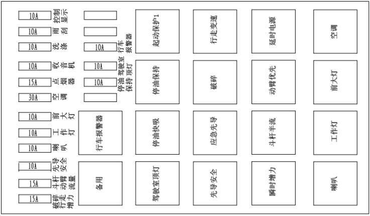
Wiper
Washing Radio
Cigarette Lighter
Air-conditi oning
Headlamp
Work light Horn Pilot safety
Stick and boom flow
Breaking & traveling boosting
3.5.3
Traveling alarm Spare
Cab top light
Oil stop And remain
Travelingalarm
Fuel cutoff and maintain.
Fuel cutoff and quickactuation
Cab toplight
Fuse is the part with large current in the circuit and it protects the electrical components and wires from getting burnt
If the machine is not energized when turning the starter switch to the ON position, the fuse may have melted. Under such condition, check the fuse and replace it if necessary.
3.6 Controller
The controller of this machine is installed in the control box located at the left side of the machine
Attention
1. Do not spray water or mud on the controller, otherwise, failure will be caused.
2. If the controller is abnormal, please do not disassemble it by yourself and contact Zoomlion or Zoomlion dealers for repairing.