15 minute read
HITCHES

from Zetor Tractor Forterra 100 Forterra 110 Forterra 120 Forterra 130 Forterra 140 Operator’s Manual

REAR THREE-POINT HITCH
28 mm the upper draw-bar opening 25
Persons that are not authorized to work with the attached implement must not stand between the tractor and the hitched machine (implement) - (A). Do not park the tractor with an attached implement in the lifted position (B). During a drive without an implement the lower draw-bars (5) must be connected with springs and the upper drawbar (1) must be inserted into the spring suspension! During transport of implements the limiting drawbars (4) of the lower draw-bars must be adjusted in such a way to avoid unwanted lateral movement of the implement!
HEIGHT ADJUSTMENT OF THE LIFTING DRAW-BARS
Lifting draw-bar - see fig. (A): After disconnecting the upper end of the lifting draw-bar from the pin of the hydraulic arm make the adjustment by turning the lug (1).
Lifting draw-bar - see fig. (B): Extend the capstan (2) in the arrow direction and make the adjustment by turning the capstan.
Depending on the equipment of the tractor both the draw-bars may be designed as in fig. (B).
FIXED AND FREE POSITION OF THE LOWER HYDRAULIC DRAW-BARS
Fixed position of the lower hydraulic draw-bars (A):
The pin head (1) and washer (2) are installed horizontally.
Free position of the lower hydraulic draw-bars (B):
The pin head (1) and washer (2) are installed vertically.
The free position enables free connection of the tractor and implement. In this case both the draw-bar ends may move freely against each other as regards their height.
LIMITING DRAW-BARS
The limiting draw-bars - stabilizers (1) limit or completely prevent lateral swinging of the lower draw-bars. The adjustment of the left and right limiting draw-bar is performed by turning of the draw-bar pipe, see arrow. Both the limiting draw-bars must always be installed on the tractor.
∗LOWER DRAW-BARS WITH EXTENSIBLE END PIECES
The lower draw-bars of the hitch are equipped with semi-automatic extensible CBM end pieces. They facilitate attaching of implements to the tractor. After removing of securing pegs (1) extend the end pieces (2). The extended end pieces are attached to the fixing pins of the carried implement.
After attaching the carried implement release the hydraulic arms. By lowering and the tractor reversing the end pieces (2) will slide into the draw-bars and will be automatically secured in the working position by the securing pegs (1).
Always check the position of the extensible end pieces and the securing pegs, see fig. (3).
∗LOWER DRAW-BARS WITH CBM HOOKS
The lower (3) and upper (4) draw-bars of the hitch are equipped with CBM hooks. First, suspension CBM balls (1) must be fitted to the implement and the limiting drawbars must be used to set the distance between the lower draw-bars of the hitch (3).
After reversing and subsequent lifting of the three-point hitch its lower draw-bars (3) are connected to the implement and then the driver connects the upper draw-bar (4) of the three-point hitch from the cab.
When disconnecting the implement release the hooks, with the control wires (2) lift the upper draw-bar (4) and by lowering the three-point hitch disconnect the lower draw-bars (3).
SECURING THE LOWER DRAW-BARS WITH CBM HOOKS
For especially demanding working positions (aggregation with heavy machines on slopes or aggregation with machines overhanging to one side) we recommend you to securely lock the lower draw-bar hook by inserting an M8 screw in the opening (S) and locking it with a nut.
UPPER DRAW-BAR
The upper draw-bar (1) has adjustable length. It is attached to the tractor to the console openings. When extending the upper drawbar you must make sure that both the joints are unscrewed from the draw-bar pipe to the same length.
∗FRONT THREE-POINT HITCH
It is designed for attachment of frontally carried agricultural machines and implements in accordance with ISO 8759-2. During transport of a carried implement the hitch must always be hydraulically locked in the lifted position with valves that are installed on the left side of the tractor over the front axle.
This hydraulic lock is recommended even in case no machine is attached to the three-point hitch.
FRONT THREE-POINT HITCH CONTROL
The hitch is equipped with two hydraulic cylinders that are supplied with oil from the integrated hydraulic distributor. The lifting and lowering is controlled by the control lever of the integrated distributor (1).
Position 3 Lifting
Position 4 Lowering
Position N Hitch lock
ADJUSTING THE LOWERING RATE OF THE FRONT THREE-POINT HITCH
Before the start of work with an implement attached to the front three-point hitch it is recommended to adjust the time necessary to lower the implement from the highest to the lowest position to 1 - 1.5 s by setting the throttle valve. By turning the valve body to the left (in the arrow direction) you will increase the lowering speed. During the adjustment the valve levers of the front hitch must be directed horizontally.
HYDRAULIC LOCK OF THE FRONT THREE-POINT HITCH
Hydraulic locking of the front three-point hitch is performed in any position of the hydraulic cylinders with the ball valve in the front part of the tractor (2).
A Free position
Valve levers are in the horizontal position
- The hitch can be controlled from the cabin
B Locked position
Valve levers are in the vertical position
- The hitch is locked
WORKING AND TRANSPORT POSITION OF THE FRONT THREEPOINT HITCH
A Working position of the front three-point hitch
B Transport position of the front three-point hitch
Changing the position of the draw-bars of the front three-point hitch:
1. Release and remove the pin (1) from the opening.
2. Lift the arm from position (A) to position (B).
3. Lock the arm by inserting the pin (2) in the opening (2) and secure the pin. Only insert the pin in the openings, never check whether the opening is free with your fingers!
DRIVING WITH AGRICULTURAL MACHINES ATTACHED TO THE FRONT THREE-POINT HITCH
The maximum permissible speed of the tractor with agricultural machines attached to the front three-point hitch is 15 km/h. If no implement or weight is attached to the front three-point hitch, we recommend you to lift the lower lifting draw-bars to the transport position.
Wheel Track Change
Wheel Track Change
Possible Adjustable Tracks Of The Front Wheels Of The Front Driving Axle Of The Tractors
Note: Use of different tyre dimensions with individual tractor types - see chapter Main technical parameters.
Tighten the front wheel nuts with the torque of 250 - 290 Nm.
Tighten the nuts connecting the wheel bead with the wheel disc with the torque of 200 - 220 Nm.
You can change the wheel track by changing the position of the rim and disc. First, secure the tractor against moving, lift the axle with a lifting jack and support it.
−Loosen the nuts of the screws connecting the disc with the rim and remove the screws.
−Change the track by setting the rim in the required position.
−Re-install the screws with washers and secure them with nuts. Tighten the nuts with the torque of 230 - 250 Nm.
−After every loosening of a bead connection tighten the screws to the prescribed value.
−After driving 100 m with the tractor without load re-tighten the connections with the prescribed torque.
−After loading the tractor re-tighten the connections after 3 hours of work.
−After 10 hours of work check the tightening of the nuts of discs and wheel rims again.
Wheel Track Change
FRONT WHEELS TRACK OF FRONT DRIVE AXLE IN TRACTORS EQUIPPED WITH NON-REMOVABLE DISCS
F_02_189
TOE-IN OF THE WHEELS OF THE FRONT DRIVING AXLE
Proper toe-in of the front wheels of tractors with the front driving axle is 0 to 2 mm and is measured on the front wheel hub flanges (if the front wheels are installed, you can measure toe-in on the wheel rims).
Toe-in “S” is determined by the difference of the measured values: S = b - a.
ADJUSTMENT OF TOE-IN OF THE WHEELS OF THE FRONT DRIVING AXLE
−Set the wheels symmetrically with the longitudinal axis of the tractor.
−At the front on the horizontal plane of the wheel axes measure, in accordance with fig. F_02_189, the distance between the rims. Mark the place of measurement.
−Drive the tractor to move the marked places to the horizontal plane of the wheel axes at the back (turning by 180°) and measure the distance between the marked places again.
−Release the locking nuts of the heads of the ball screws (2) of connecting rods of the steering at the hydraulic cylinder.
−Adjust the toe-in value by turning the shank of the ball screw (3). Perform the adjustment of both the joints symmetrically to maintain the same turning radius at both the sides (perform the measurement at the rim sides).
−Tighten the locking nuts of the heads of the ball screws (2) with the torque of 122136 N. The upper surfaces of the heads (1) must be parallel.
Wheel Track Change
Front Drive Axle Fenders
Front drive axle fenders can come in two designs
A - Fenders with solid consoles where the axis of fenders turn corresponds with the axis of front wheel turn. Fenders are on adjustable holders that can be set according to required tracks and the type of tyres used on the side (by relocating screws (a) to different openings) and also in terms of height (by relocating screws (b) to different openings).
B - Fenders with turnable consoles where the axis of turning corresponds to the axis of front wheel only partially. This design enables the setting of greater front wheels lock. Fenders are on adjustable holders which can be set according to the kind of tyres used in terms of height (by relocating screws (b) to different openings).
Wheel Track Change
F13BN0033
Setting The Wheel Lock With Front Drive Axle
Perform the setting of lock with every change of wheel track or tyre replacement with front drive axle. The locks with front drive axle must be set so that the distance between the front drive axle tires and the tractor with full wheel lock and full swing of axle around central pivot is at least 50 mm.
Wheel Lock Setting Inspection With Front Drive Axle
1. Set the full wheel lock to one side and check that the distance between a tire and the nearest stable point on the tractor is at least 50 mm. Perform the inspection with both front tires.
2. Switch the steering to full wheel lock to the other side and perform the inspection according to article 1
3. Heave one side of front axle with a heaver to the maximum swing (the front drive axle is leaning against a console) and perform the inspection according to articles 1 and 2.
4. Heave with a heaver the second side of the front axle to the maximum swing (the front axle is leaning against console) and perform the inspection according to articles 1 and 2.
The setting of lock (A) changes after slackening the nut (2) and unscrewing or screwing in the screw (1).
After the change of wheel lock with front drive axle it is always necessary to perform the inspection of their setting pursuant to articles 1 to 4.
Rear
Depending on the width of the rear tyres you can set the wheel tracks in the following range:
Rear Wheel Track Adjustment
Rear wheel tracks are adjustable with the step of 75 mm and the adjustment is performed by changing the position of the rim and disc with the rear part of the tractor lifted so that the wheels can rotate freely.
Before the lifting do not forget to secure the tractor against moving by wedging the front wheels.
After changing the wheel track tighten all the screws connecting the disc with the rim with the torque of 200 - 220 Nm and the nuts of the screws connecting the disc with the wheel shaft with the torque of 400 - 470 Nm.
−After every loosening of a bead connection tighten the screws to the prescribed value.
−After driving 100 m with the tractor without load re-tighten the connections with the prescribed torque.
−After loading the tractor re-tighten the connections after 3 hours of work.
−After 10 hours of work check the tightening of the nuts of discs and wheel rims again.
Note: Use of different tyre dimensions with individual tractor types - see chapter Main technical parameters.
−Until reaching the first 100 hours of work perform frequent checks of tightening of the nuts of the discs and rims of the front and rear wheels (at least 6 times in the course of the first 100 hours of work).
−Then, always check the tightening of the nuts of the discs and rims of the front and rear wheels after every 100 hours of work.
Ballast weights are necessary to additionally load the tractor axles and to ensure manoeuvrability and stability of the tractor.
Bottom Weights
They are installed in case the tractor is not equipped with the front PTO into the frame tub casting cavity with screws that are accessible after removal of the battery holder.
The front weights of the can type are suspended in the tool carrier. They are protected from lateral movement with a pin inserted between the central weights. The other weights are attached to the central ones with two clamps.
Note: After the insertion of the pin the front weights and the weight carrier can be used as the front hook for emergency towing of a sunken tractor.

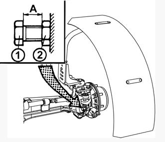
Valve For Filling Tyre Tubes With Liquid
All the tubes of the rear wheels are equipped with a valve that makes it possible to fill the tubes with liquid with the use of an adapter. Filling the tubes of the front tyres and double mounting of the rear wheels with liquid is not permitted.
Procedure Of Filling The Tyres With Liquid
1. Unload the tyre by lifting the tractor and turn it with the valve upwards (A).
2. Deflate the tyre and unscrew the valve insert.
3. Screw the adapter for water filling on and attach the liquid supply hose to it.
4. Fill the tyre with the prescribed quantity of liquid.
5. For the filling you can use a gravity tank (B) or you can fill the tyre under pressure (C).
6. Remove the hose and unscrew the adapter for water filling.
7. Screw on the valve insert and inflate the tyre to the prescribed pressure.
8. After inflating screw the protective cap on the valve.
9. Fill the other tyre in the same way.
Procedure Of Draining Liquid From The Tyres
1. Unload the tyre by lifting the tractor and turn it with the valve upwards (A).
2. Deflate the tyre and unscrew the valve insert; turn the wheel with the valve downwards.
During draining of liquid vacuum may occur in the tyre. Therefore, turn the wheel time after time to get the valve to the upper position (B).
3. Remove the rest of the liquid after screwing on the adapter for water filling by supplying pressurized air (C).
4. Blow out the liquid until it stops running through the tube of the air adapter.
5. Unscrew the adapter for water filling
6. Screw the air part of the valve back on and inflate the tyre to the prescribed pressure.
7. Screw the protective cap on the valve.
8. Drain the liquid from the other tyre in the same way.
Wedging The Front Wheels
Before lifting the rear wheels do not forget to secure the tractor against moving by wedging the front wheels.
Ballast Weights
MAXIMUM LIQUID WEIGHT (KG) BY TYRE DIMENSIONS
Calcium chloride solution CaCl2 (kg) Water (l) Extra load-
The table mentions values for temperatures down to - 30°C.
ANTIFREEZE SOLUTION FOR TYRE FILLING
Ballast Weights
An antifreeze solution may only be used for filling tyres if you have purchases additional tubes! Caution, the tractor is equipped with tubeless tyres by the manufacturer!
Solution preparation:
1.Dry calcium chloride CaCl2 is added to water, never the other way round!
2.The solution is not dangerous, but it is necessary to work carefully with it. Remove spilt drops with clean water.
3.Before filling leave the solution to cool down. Observe the prescribed quantity of hydrated lime.
4.The solution must not get in contact with metal parts and the electric installation! The solution is not harmful for the tube valve.
5.The antifreeze solution with the above mentioned composition must not be used in the cooling system!
6.After draining dispose of the antifreeze liquid as special waste!
No additional interventions into the electric installation (connection of other electric appliances) are permissible due to its possible overloading!
Electric System
Basic Service Information
12V/155Ah 12 V Alternator with a built-in voltage controller (2)
14V / 100A Starter motor with a reducer (3)
12V / 3 kW
Drive V-belts of the alternator and water pump
AVX10x1385Laservice
The battery must always be connected with the “minus” pole to the ground and with the “plus” pole to the alternator. If the battery is connected the other way round, it will destroy the whole semiconductor equipment of the alternator. When starting the tractor with the use of an auxiliary battery, do not forget to connect the terminals “plus” to “plus” and “minus” to “minus”. If you replace a part of the charging circuit, disconnect the battery from the tractor ground (-) with the battery disconnector. This way you will avoid accidental short-circuits on the terminals.
In case of any handling or repair of the started motor the minus pole of the battery must be disconnected and all the shifting levers, incl. the PTO shifting lever, must be in the neutral position (do not forget to check whether the locked PTO switches on the right cabin pillar are off as well to prevent spontaneous start and endangering of the service person's life).
It is forbidden to start the engine by short-circuiting the starter motor terminals.
Only start the tractor from the driver’s seat!
Accumulator Battery
The accumulator battery is installed under the cover on the left side of the tractor under the cab step. The battery is accessible after folding up of the cab step.
During folding up of the cab step the cab door must be closed.
1- Remove the screw (1).
2- Lift the step in the arrow direction
3- Secure the lifted step with a screw inserted to the opening (2) in the step
4- Remove the safety pin (3)
5- Grasp the bottom edge of the cover and remove it.
Battery Disconnector
The battery disconnector is located at the left-hand side of the tractor near the starter motor.
a- Battery connected b- Battery disconnected ¨When shutting down the tractor disconnect the battery with the battery disconnector (1). By this you will interrupt the permanent minimum current consumption of the warning light interrupter (approx. 10 mA).
If the tractor is out of operation for a longer period of time, it is necessary to charge the battery at least once every three months due to its spontaneous discharging.
Accumulator Battery Maintenance
Keep the accumulator battery clean and properly fixed to the vehicle. However, the fixing device must not deform the battery case. In the case of polypropylene batteries the electrolyte level must not be below the minimum mark indicated on the case. Only add distilled water to the battery!
1. When working with the battery first read the attached manual.
2. During work with the battery protect your eyes with goggles or a safety shield!
3. The electrolyte is a caustic substance; therefore, handle it with proper care. If your skin or clothes get stained by electrolyte, wash the skin or clothes with water and neutralize them with soap.
4. During charging hydrogen is released from the electrolyte on the electrodes. Hydrogen mixed with the air forms an explosive mixture. Therefore, it is prohibited to handle open fire near the battery during charging.
5. An explosion may also be caused by a spark created on the disconnection or release of a terminal when the charging circuit is on.
6. Keep the battery out of reach of children!
7. A discarded battery is dangerous waste for the environment - when buying a new battery hand the old one over to the dealer, who will dispose of it free of charge.
Alternator
It is accessible after removal of the right side plate. Charging is monitored by the red indicator on the combined dashboard instrument.
If the 12 V 2 W indicator bulb gets burnt, it must be replaced immediately. During repairs of the tractor by electric welding all the conductors must be disconnected from the alternator. Protect the “+B” conductor from a short-circuit.
Alternator Maintenance
When washing and cleaning the tractor protect the alternator from penetration of water or diesel fuel!
During operation the alternator must not be disconnected from the battery! The alternator must never be put in operation without load, i.e. with the conductor disconnected from the “+B” terminal and the “+D” terminal connected. Such a condition may induce an extremely high voltage when the engine speed is increased, which would destroy the semiconductors! Never short-circuit any alternator terminal during operation! The alternator must not be additionally excited. Such an intervention would damage the semiconductors. Ensure perfect electric connection of the alternator terminals and proper grounding of the alternator!
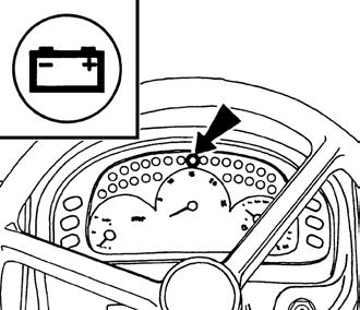
Charging Control
Charging control has two functions. If there is

1. red light with the engine running, it is a charging failure,
2. orange light signalizes a state when electrical installation of tractor has such intake that the performance of alternator is insufficient for charging the accumulator.

If this condition occurs, turn an appliance off and the control is off.
The engine operation with a lit orange charging control can result in accumulator depletion.
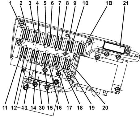
Fuse Box
It is accessible after removing of the left lid of the steering console. The fuses (1) are of the knife type and in case of replacement the prescribed fuse value must be observed. In case of repeated replacement of a fuse consult the nearest repair shop. The glowing fuse (2) is of the band type with the value of 30 A.