2 minute read
ELECTRO-HYDRAULIC SYSTEM

from Zetor Tractor Forterra 100 Forterra 110 Forterra 120 Forterra 130 Forterra 140 Operator’s Manual

Symbol of the minimum lowering speed
Free Position
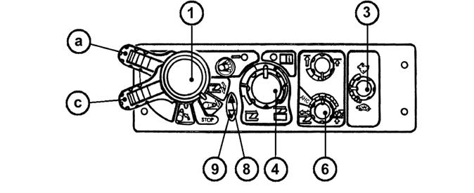
For permanent work with free hydraulic system, e.g. during work with a plough with a support wheel the position of the control (4) under the indication (A) and the position of the control (6) at the positional control symbol is used.
In the vibration dampening mode and during the use of the rear control buttons the lowering speed setting is out of function.
ahc_01
F_02_172a SETTING THE CONTROL OF THREEPOINT HITCH
Electrohydraulics enables two ways of three-point hitch control.
A.Manual control setting - control (6) is set in the range see arrow

B.automatic control - control (6) is set in HitchTronic (AHC) position see arrow
Automatic control can be at any time exchanged for manual and the other way round by a control (6).
MANUAL SETTING OF CONTROL OF THREE-POINT HITCH
Perform according to “Cancel blocking” part and set the required position of elements with regard for the nature of performed works. To reach the depth of working tools, there is a control (4). For setting the kind of control and its mixing, use a control (6).
Power control symbol
The activity of control (lifting and lowering) can be monitored by means of indication diodes (8) and (9). Na shift the lever (1) (a) position, after turning, set again to (c) position. Control system takes the previous working position (memory of ploughing). For setting the required speed of starting, there is a control (3).
Position control symbol
AUTOMATIC CONTROL OF THREE-POINT HITCH
Do the step according to “Cancel blocking” part. Set the control (6) to HITCHTRONIC (AHC) position. By control (4), set the working depth of tools attached to rear threepoint hitch.
When the implement attached in the rear three-point hitch reaches the depth set by the control (4), control system measures the soil resistance and this value is used as default for further control.
The activity of controls (lifting and lowering) can be monitored by means of indicated on diodes (8) and (9).
At dead end, shift the lever(1) to (a) position, after turning set the (c) position again. For setting the required speed of lowering, there is a control (3). After reaching the depth set by the control (4) control system again measures the soil resistance and this value is used as default for further regulation.
Using The Rear Control
The rear control is used to connect and disconnect implements. The lifting switching lever (1) on the EHR-B electrohydraulic control panel must be in position (b) or (c). The designation symbols of buttons on both the tractor fenders correspond to the movement direction of the three-point hitch after their pressing. The movement only lasts as long as the button is held.
Every use of the rear control causes blocking of the control system and the “Blocking cancellation” must be repeated - see page 130.
EXTERNAL CONTROL BUTTONS OF THE ELECTRO-HYDRAULIC SYSTEM

1.Lifting
2.Lowering
The movement only lasts as long as the buttons are held.
The external control buttons of the electro-hydraulic system are functional without prior activation of the system.
Using The Buttons
When handling the three-point hitch with the external control buttons the operator must stand out of reach of the connected implement to avoid being caught or injured by the implement.
F -02 -173
INDICATION OF EHR-B ERRORS
The electronic part of the electrohydraulic system continuously checks proper functioning of the system. Possible errors are indicated by repeated flashing combinations of the diagnostic LED (7).
After the remedy of the error the diagnostic LED (7) goes off.
Permanent illumination of the diagnostic LED (7) indicates the state of blocking of the electro-hydraulic system.