15 minute read
DRIVING OPERATION

from Zetor Tractor Forterra 100 Forterra 110 Forterra 120 Forterra 130 Forterra 140 Operator’s Manual

Before You Start
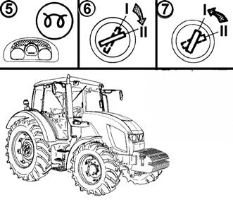
Before you start the engine, make sure:
1.that the tractor is properly braked
2.that the main gear shifting lever and the reversing lever is in the neutral position
3.that the PTO switches on the right cab pillar are off.
If the clutch pedal is not pressed, the engine cannot be started - the starting interlock switch is not actuated.
If The Engine Will Not Start
Return the key to position “0”. Wait for 30 seconds and repeat the start. Never support the stopping engine with the starter motor. There is a danger of damaging the starter motor.
Prohibited Starting Methods
It is forbidden to start the engine by short-circuiting the starter motor terminals. Only start the tractor from the driver’s seat! During any handling or repair of the started motor the minus pole of the battery must be disconnected and all the shifting levers, incl. PTO must be moved to the neutral position. The starter motor contacts are covered with a cap.
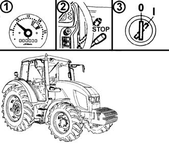
Starting The Tractor Engine


The tractors are equipped with glowing plugs in the cylinder heads as standard.
1.Insert the key into the switching box (position “0”).
2.Depress the clutch pedal.
3.Move the main shifting lever and the reversing lever to the neutral position.
4.Turn the key to position “I”. The yellow indicator signalling proper function of glowing will light up on the dashboard.
5.Wait until the glowing indicator goes off (the time depends on the temperature of the cooling liquid).
If the glowing indicator only flashes instead of lighting, an error has occurred in the glowing system (chapter Indication of errors of the glowing system). Have the reported error repaired in a specialized repair shop.
6.Turn the key to position “II” (start).
7.Release the key immediately after starting the engine. Do not start the engine for more than 15 s.
Indication Of Errors Of The Glowing System
An error of the glowing system is indicated by flashing of the glowing indicator.
-If at engine standstill the glowing indicator flashes once a second, the glowing will occur in the emergency mode as at low temperatures regardless of the coolant temperature.
-If at engine standstill the glowing indicator flashes twice a second, the glowing is off (out of operation).
-If the glowing indicator flashes permanently during engine operation, the glowing controller is faulty and the glowing has not been finished. This failure must be removed immediately as the battery might get discharged.
Coolant Heater
The coolant heater is installed on the engine block.
The output of the heater is 1000 W at the 220 VAC supply voltage.
Starting The Engine With The Use Of The Coolant Heater
Heating the coolant facilitates engine starting at low ambient temperatures. The electric installation of the power supply and its protection against electric shock must comply with valid regulations.
1. First, insert the connector to the heater.
2. Then, connect the heater to electric mains with the voltage of 220 V.
With regard to reduced wear of the engine during starting at low temperatures, the use of the heater is recommended by the manufacturer. The heating time depends on the ambient temperature (1 - 2 hours before the planned start should be sufficient). After the end of heating first disconnect the device from the electric mains and only then remove the connector from the heater!
Electric shock hazard!
It is necessary to ensure instructing of the tractor operator and regular inspections of the coolant heater, incl. the power supply cable in the sense of valid standards of the state where the tractor is operated, at least before every winter.
Immediately After Starting
After starting set the engine speed to 800 - 1000 rpm and let the engine run without loading for approx. 2 minutes.
During this time check the lubrication, charging, hydrostatic steering (the indicators must go off) and other functions ensuring proper operation of the engine. The period of running the engine without loading must be observed, especially in winter.
Engine Preheating
Continue preheating the engine while driving. Preheating the engine by means of a long idle run or abrupt increasing of the engine speed is harmful for the engine.
Until the coolant temperature reaches 45°C, do not exceed the engine speed of 2000 rpm.
Gear Shifting
The tractors are equipped with a fourspeed synchronized gearbox, threestage torque multipliers and two-speed reduction.
The four-speed gearbox is controlled with the main shifting lever with control buttons of the torque multiplier (1). The forward and reverse motion of the tractor is selected with the reversing lever (2). The gearbox does not make it possible to use the fourth speed for the reverse motion.
Reversing Lever
The reversing lever is used to select the driving direction of the tractor (forward, reverse).
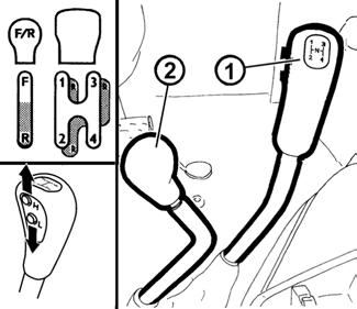
F - Forward drive
N - Neutral
R - Reverse drive
The reversing gearbox offers 18 reverse speeds that are approximately as fast as the forward speeds. Therefore, consider well and select a suitable reverse speed for the particular character of work. Shift the reversing lever with the clutch pedal depressed and the tractor standing. To drive in the reversing direction move the reversing lever to the R position.
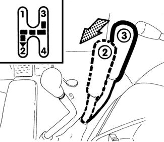
Shifting Of Road And Reduced Gear Speeds
H - Road gears
N - Neutral
L - Reduced gears
Shifting of gears of the main gearbox at reduced gear speeds is the same as in the case of road speeds
The shifting lever of road and reduced speeds can only be shifted with the tractor at standstill.
Shifting From Lower To Higher Gear Speed
Depress the clutch pedal (clutch disengaged). At the same time release the foot throttle pedal and shift the required higher gear. Smoothly release the clutch pedal (the clutch starts engaging) and at the same time increase the engine speed.
Shifting From Higher To Lower Gear Speed
Depress the clutch pedal and move the shifting lever via the neutral position to the lower gear.

Note: To extend the life of the synchromesh you can shift the gear from higher to lower speed using the “double clutch depressing”.
THREE-STAGE TORQUE MULTIPLIER
The three-stage multiplier is standard equipment of all tractor types. Shifting of individual stages of the threestage multiplier is controlled with two buttons on the main shifting lever head. It is performed without depressing of the travelling clutch pedal (under load). The entire shifting is automatic even when the tractor is loaded.
H - 1.00 ratio (high stage)
M - 1.16 ratio (medium stage)
L - 1.34 ratio (low stage)
Indication Of The Multiplier Function
Individual engaged stages of the multiplier (H,M,L) are signalled by indicators on the dashboard with the tortoise symbol.
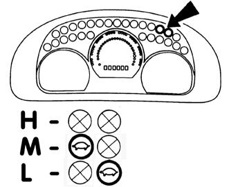
H
- Symbols OFF
M - One indicator with the tortoise symbol is lit.
L - One indicator with the tortoise symbol is lit.
Note: On starting or stopping of the tractor engine the H stage is always engaged automatically.
Shifting The Stages Of The Torque Multiplier
H - Increasing the travelling speed
L - Reducing the travelling speed
INCREASING, REDUCING THE TRAVELLING SPEED BY TWO GEARS
2xH Increases the travelling speed by two gears
2xL Reduces the travelling speed by two gears
F13BN032
Signalizing Failures In Gear Box Hydraulic Circuits
Gear box hydraulic circuit failures are signalized by a repeated combination of gear box failure control (red).
Gear box hydraulic circuits failures description

Blinking combination Long
Failure description Popis závady závady once once or twice Switchboard main valve circuit failure twice once or twice PTO clutch valve circuit failure three times once or twice PTO shaft 540/1000 revolutions switch valve circuit failures four times once or twice Multiplier torque valve circuit failure five times once or twice Multiplier torque valve circuit failure six times once or twice PTO shaft 1000 revolutions control circuit failure
Setting In Motion
1.Select road or reduced gears.
2.Depress the clutch pedal.
3.Shift the main shifting lever and the reverse lever to the neutral position and switch off the PTO switches on the right cab pillar.
4.Start the engine
5.Set the engine speed to 800 rpm.
6.Shift the reversing lever to the requested driving direction of the tractor (forward or reverse).
7.Select the suitable gear for putting the tractor in motion.
8.Slightly increase the engine speed.
9.Get the parking brake ready for releasing.
10.Release the clutch pedal until the travel engagement point and while simultaneously increasing the engine speed continue releasing the clutch pedal smoothly.
11.Release the parking brake completely.
12.Start moving smoothly and slowly. Very fast acceleration may cause overloading of the power train, increased fuel consumption, excessive wear of tyres and damage of the transported load. Only use the 1st gear to put the tractor in motion when driving with a heavy trailer uphill and in rough terrain.
When shifting individual gear speed (1-4) or reversing (F-R) observe the instructions for putting the tractor in motion and gear shifting in this manual. When the tractor has been started and is still standing, depress the clutch pedal and wait for approx. 2 seconds. Only then shift the required gear speed or select the reverse direction.
To increase safety and to avoid unexpected situations use the foot brake during the shifting as well.
Driving Uphill
When driving uphill, shift from the higher to the lower speed in time to avoid the engine speed dropping below 800 rpm and avoid such driving that would lead to stopping of the engine due to overloading.
Driving Downhill
Driving downhill without an engaged gear is prohibited. When driving down a longer slope, shift the lower gear, the steeper the slope is. If possible, shift the lower gear before the slope already.
Note: The gear that allows you to get uphill reliably is also suitable for getting down the hill safely.
Foot Brakes
The foot brakes are of the disc, wet, hydraulically controlled, double-pedal type with an automatic pressure compensator. During driving on a road both the pedals must be connected with a latch. Only use unlatched pedals for braking the right or left wheel separately during terrain work and in the field. Note: When driving down a steep slope with a trailer or semi-trailer equipped with air or hydraulic brakes you must use the foot brake from the beginning of the slope already.
During braking with one brake pedal the trailer brakes are not in operation!
AIR BRAKES OF TRAILERS AND SEMI-TRAILERS
The control of the air brakes of trailers (semi-trailers) and the control of the tractor brakes is designed in such a way that the braking effect of both the vehicles is synchronized.
The working pressure is set by the pressure controller to 740 ± 20 kPa. If the pressure drops below 550 - 40 kPa, the relief valve puts the secondary devices (differential lock, engagement of the front driving axle, etc.) out of operation.
Warning Indication Of An Air Pressure Drop
A pressure drop below 450 kPa is signalled by lighting up of the red indicator located on the dashboard. In case of a pressure drop below 450 kPa in the air pressure system a tractor with a braked trailer or semi-trailer must not continue travelling until the air pressure increases again.
SINGLE-HOSE AND DOUBLE-HOSE BRAKES
1.Coupling of single-hose brakes
2.Couplings of double-hose brakes
After disconnection or without a connected trailer (semi-trailer) the couplings must be closed with a cap.
SINGLE-HOSE BRAKES
The cap is marked black. After connection of a trailer (semi-trailer) with the maximum permissible speed approved for the particular tractor type the maximum allowed speed of the set is 30 km/h.
The maximum permissible speed of the set results from the maximum permissible speed of the slower vehicle in the set.
DOUBLE-HOSE BRAKES
The cap of the left coupling is marked yellow (braking branch) and the cap of the right coupling is marked red (filling branch).
After connection of a trailer (semi-trailer) with the maximum permissible speed approved for the particular tractor type the maximum allowed speed of the set is 40 km/h.
The maximum permissible speed of the set results from the maximum permissible speed of the slower vehicle in the set.
Hydraulic Brakes Of Trailers
Connect the hydraulic brakes of a trailer or semi-trailer to the quick-coupler marked with an arrow.
The control of the hydraulic brakes of trailers (semi-trailers) and the control of the tractor brakes is designed in such a way that the braking effect of both the vehicles is synchronized. The working pressure is applied by oil delivered by a permanent gear pump of the hydraulic system.
The brake valve of the trailer is controlled by the pressure of the brake liquid from the main brake cylinders depending on the force applied onto the brake pedal. At the maximum depression of the brake pedal the pressure at the coupling must amount to 12 - 15 MPa. The brake valve makes sure that the brake function overrides the hydraulic function.
If during depression of the foot brake pedals shocks occur in the hydraulic circuit, it is necessary to bleed the hose leading from the brake valve to the quick-coupling.
During driving with a hitched trailer or semi-trailer the pedals of the foot brake must be connected and secured with a latch.
During braking with one brake pedal the hydraulic brakes of the trailer are not in operation.
CONNECTING AND DISCONNECTING QUICK-COUPLERS OF HYDRAULIC BRAKES OF THE TRAILER
When connecting and disconnecting the quick-couplers pay increased attention with regard to the residual oil that remains in the socket or on the plug of the quick-coupler.
For environmental reasons after every disconnection of quickcouplers this residual oil must be removed with any textile material.
Front Driving Axle Control
a - Front driving axle “OFF” b - Front driving axle “ON”
When the tractor is stopped (the tractor is braked, engine stopped, key of the switching box off), the front driving axle is “OFF”.
Driving With The Front Driving Axle Engaged
Use the front driving axle in case the rear wheels slip to increase the traction of the tractor.
On a road and hard surface driving with the front driving axle engaged is acceptable up to the maximum speed of 15 km/h (driving with the front axle engaged causes increased wear of the front tyres).
Permanent engagement of the front driving axle is permissible if an agricultural machine or implement is attached to the front of the tractor. This condition is mentioned in the operator’s manual of the corresponding machine. The maximum allowable speed of these sets is 15 km/h.
STOPPING THE TRACTOR - PARKING BRAKE
Under normal conditions stop the tractor slowly. Shortly before stopping:
1.Depress the clutch pedal.
2.Shift the main gear shifting lever to the neutral position.
3.After every stopping secure the tractor against accidental movement with the parking brake. Activation of the parking brake is signalled by illumination of the corresponding indicator on the dashboard.
Stopping The Engine
After work of the tractor when the engine was fully loaded, the engine must be left to cool down.
1.Before stopping the engine reduce the engine speed to 800 - 1000 rpm and let the engine run without loading for approx. 5 minutes.
2.Move the manual throttle lever to the STOP position.
3.The engine stops when the key is switched from “I” position to “0” position.
Leaving The Tractor
If the tractor is standing on a slope, it must be secured against spontaneous movement: braked with the parking brake, engine stopped, the reversing lever shifted depending on the tractor inclination on the slope either in the forward or reverse position, the main shifting lever engaged in a low gear position and the wheels secured with wedges. Before leaving a tractor with the safety cab remove the key from the switching box and lock the cab.
Warning Indication Of A Hydrostatic Steering Error
An error of the hydrostatic steering pump is signalled in case of a pressure drop below 120 kPa downstream of the pump on the dashboard by the corresponding symbol.
Note: During starting of the engine or at low engine speed the indicator may flash slightly; if after starting or increase of the engine speed the indicator goes off, it is not an error.
General principles for running in the new tractor in the course of the first 100 hours of operation........................................................................................70 During the first 10 hours............................................................................................70 From 100 hours on....................................................................................................71
General Principles For Running In The New Tractor In The Course Of The First 100 Hours Of Operation
During the first 100 operation hours:
- Load the engine normally
- Avoid operation under partial loading of the engine
- Avoid excessive idle run
- Frequently check the oil level in the engine (increased oil consumption is normal in this period).
- Check screw connections mainly of the supporting parts of the tractor.
- Immediately remove all established shortcomings; thus, you will prevent subsequent damage and possible impairment of operation safety.
- Proceed in the same way after a general overhaul of the tractor as well.
During The First 10 Hours
- Run in the tractor in the transport regime.
- Tighten the fitting nuts of the front and rear wheels, including the bead / rim connections at the prescribed torque.
From 100 Hours On
After running-in you can work with the tractor without any restrictions.
Recommended operation speed 1400 - 2300 rpm
Idle speed 800 ± 25 rpm
Operation oil pressure 0.2 - 0.5 MPa
Oil pressure at the idle speed min. 0.05 MPa
Max. coolant temperature 106°C
Before you start, make sure that the technical condition of the tractor corresponds to requirements for safe operation. When a trailer or implement is attached, check its connection and proper fixation of the load. Never leave the tractor while it is moving to connect the trailer by yourself. Also take care of your assistant’s safety.
CBM stage quick-adjusting hitch...............................................................................74
Height adjustment and disassembly of the CBM stage hitch.....................................74
Automatic mouth of the CBM stage hitch..................................................................74
Modular system of hitches for trailers and semi-trailers............................................75
Swinging draw-bar console module ...........................................................................75
Swinging draw-bar .....................................................................................................75
Swinging draw-bar console with a fixed pin module..................................................75
Console with a ø 80 ball module ...............................................................................76
Hitch for a single-axle CBM semi-trailer ....................................................................76
Maximum permissible vertical static load of hitches for trailers and semi-trailers......77
CBM STAGE QUICK-ADJUSTING HITCH
It is designed for attachment of doubleaxle trailers or lighter single-axle semitrailers. The guiding mouth is height adjustable. During work with various implements it may be necessary to adjust the height of the hitch or to disassemble the entire hitch.
Height Adjustment And Disassembly Of The Cbm Stage Hitch
By moving the control lever in the arrow direction to position (1) you will release the lever and by moving it subsequently to position (2) you will retract the locking pins (3). Now, the stage hitch is released and you can adjust its height or disassemble it.
When you release the lever from position (2), the locking pins (3) will extend and the lever will automatically return to the initial position.
Automatic Mouth Of The Cbm Stage Hitch
When the lever (1) is moved in the direction of the arrow (a), the pin (2) is retracted to the upper position, which is signalled by the extended indicator (3), see fig. (A).
When the mouth gets onto the shaft lug, the pin will automatically slide into the lug of the connected trailer. You can lower the hitch pin (2) manually by moving the lever (1) in the arrow (b) direction. The insertion of the pin is signalled by the retracted indicator (3), see fig. (B).
After the attachment of the trailer you must always check whether the indicator (3) is retracted in accordance with fig. (B).
MODULAR SYSTEM OF HITCHES FOR TRAILERS AND SEMI-TRAILERS
Module types:
Fig. (B) - Swinging draw-bar console
Fig. (C) - Swinging draw-bar console with a fixed pin
Fig. (D) - Console with a ø 80 ball
Disassembly, fig. (A):
1- Remove the locking screw (1).
2- Secure the module against sinking, release and disassemble the pins (2).
3- Slide the module out of the console downwards.
Do the assembly in the reverse order.
SWINGING DRAW-BAR CONSOLE MODULE
The swinging draw-bar console module is located in the stage hitch console.
SWINGING DRAW-BAR
Disassembly:
1- Release and remove the pins (1).
2- Slide the swinging draw-bar out in the arrow direction.
Do the assembly in the reverse order.
SWINGING DRAW-BAR CONSOLE WITH A FIXED PIN MODULE
Perform the assembly and disassembly of the swinging draw-bar in accordance with the “Swinging draw-bar” chapter.
Connecting the shaft lug to the fixed pin (3):
1- Release and remove the pin (1).
2- Lift the locking wedge (2) in the arrow direction.
3- Connect the shaft lug to the fixed pin (3):
4- Return the locking wedge (2) to the original position and secure it with the pin (1).
Console With A 80 Ball Module
The console with a ø 80 ball is only used to connect semi-trailers with a hitching device designed for a ø 80 ball.
Releasing the hitch, fig. (A):
By moving the lever (1) in the arrow direction you will remove the locking wedge (2).
Locking the hitch, fig. (B):
By moving the lever (1) in the arrow direction you will retract the locking wedge (2).
HITCH FOR A SINGLE-AXLE CBM SEMI-TRAILER
The hitch for a single-axle semi-trailer may be equipped with a hook (A) or with a swinging draw-bar (B).
Replacing the hook with the swinging draw-bar (C):
1- Lower the hitch.
2- Release and remove the pin (1).
3- Remove the hook in the arrow direction.
Install the swinging draw-bar in the reverse order.
MAXIMUM PERMISSIBLE VERTICAL STATIC LOAD OF HITCHES FOR TRAILERS AND SEMI-TRAILERS
Hitch pin Ø Hitch type Permissible vertical static load
Hitch pin Ø Hitch type Permissible vertical static load Hitch class C 2,000 kg 31 mm 2,000 kg 38 mm 2,000 kg
Hitch pin Ø 28 mm Hitch class D2 Hitch class D3 2,000 kg 43 mm 2,000 kg 50 mm
The maximum weight of an aggregated braked trailer or semi-trailer must not exceed the value specified on the data plate of the tractor and the value specified in the technical certificate of the tractor. The maximum permissible speed of the set results from the maximum permissible speed of the slower vehicle in the set.
Hitch of class C: max. weight of the trailer 6,000kg.
Hitch of class D2: max. weight of the trailer 14,000kg.
Hitch of class D3: max. weight of the trailer 20,000kg.
MAXIMUM PERMISSIBLE VERTICAL STATIC LOAD OF HITCHES FOR TRAILERS AND SEMI-TRAILERS
The maximum weight of an aggregated braked trailer or semi-trailer must not exceed the value specified on the data plate of the tractor and the value specified in the technical certificate of the traktor. The maximum permissible speed of the set results from the maximum permissible speed of the slower vehicle in the set.