15 minute read
ACQUAINTANCE

from Zetor Tractor Forterra 100 Forterra 110 Forterra 120 Forterra 130 Forterra 140 Operator’s Manual

With The Tractor
The tractor user is obliged to get acquainted with the recommended procedures and instructions for safe operation of the tractor in advance. It is too late to do so during operation!
Safety Cab
Normally use the left side of the tractor to enter and leave the cab. When entering and leaving the cab use the three-stage steps and handles.

Pay increased attention in the area of the shifting lever and the manual throttle lever.
The safety cabin is equipped with tinted glass as standard.
Door Opening From The Outside
The cab doors can be locked from the outside.
Door Opening From The Inside
1.Lever for door opening from the inside
2.Lever for lock opening from the inside The door is held in the fully open position by a gas strut.
Driving with an open door is not recommended as the door may get damaged.
Rear Window
The rear window is equipped with a handle and in the open position it is held by gas struts. The rear window may be * heated.
We recommend you to latch the window in the closed position when driving on an uneven ground - danger of cracking of the window. Before you start work with implements attached to the rear three-point hitch make sure there is no danger of collision between the attached implement in the position of maximum lift of the three-point hitch and the open rear window. In case of interference we recommend you to work with the window closed.
Side Window
The window is secured in the partly open position with a plastic latch.
Acquaintance With The Tractor
Washer Nozzle
The nozzle is adjustable with a needle with the max. thickness of 0.8 mm.
Washer Tank
The washer tank is located on the outer rear wall of the cab.
Washer Control
The windshield washer is activated by pressing of the selector of the front twospeed wiper located on the right pillar of the cab. The maximum period of uninterrupted operation of the washer pump is 20 s.
Storage Compartment And Tool Box
The storage compartment is located at the left side of the driver’s seat. The toolbox is positioned in the rear part of the cab behind the driver’s seat.
Rearview Mirrors
Before driving or starting work adjust the rearview mirrors to be able to see the entire road or the working field. The rearview mirrors may be * heated.
Acquaintance With The Tractor
FH12N020.tif
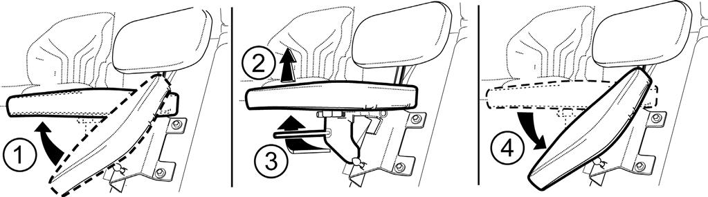
PASSENGER´S SEAT
Passenger´s seat is tiltable and placed on the left mudguard of the cabin.
Seat Tilting Out
Passenger´s seat to be tilted out in the direction of an arrow (1) upward. Locking of the seat is done automatically
Seat Tilting
Lift the passenger´s seat in the direction of an arrow (2), pull the lever (3) to the direction of the driver´s seat, tilt the seat in the direction of an arrow (4).
MARS SVRATKA DRIVER’S SEAT ADJUSTING THE SEAT FOR THE DRIVER’S WEIGHT
The seat suspension is adjustable for the driver’s weight from 50 to 120 kg. The adjustment is performed by turning a square handle. The weight adjustment indicator is located in the recess of the rear seat cover. The spring stroke is 120 mm.
Do not adjust the seat when driving. Danger of accident!
Longitudinal Adjustment Of The Seat
You can adjust the seat longitudinally with the left lever in the range of ± 75 mm (11 positions).
Vertical Adjustment Of The Seat
The seat is adjusted vertically with the lever at the right-hand side in the range of ± 30 mm (3 positions).
DRIVER´S SEAT
1- The control of setting the seat suspension according to the driver´s weight (setting by rotation, in the direction according to pictogram on the boot of the seat)
2- Longitudinal setting of the seat lever
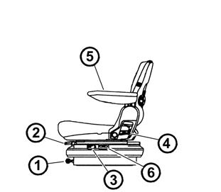
3- Seat vibrations absorption control (by tilt over of the control forward, floating position of the seat is engaged)
4- Setting the angle of rest control
5- Tilting elbow rest
6- Pneumatic suspension of seat setting control (by pulling in the direction upward, the rigidity of the suspension increases, by pulling in downward direction, it decreases)
DRIVER´S SEAT WITH MECHANICAL SUSPENSION
Control according to points 1, 2, 3, 4 and 5
Point 2, lever is placed on the right
DRIVER´S SEAT WITH PNEUMATIC SUSPENSION
Control according to points 2, 3, 4, 5 and 6
Point 2, lever is placed on the left
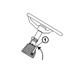
* TILTING STEERING WHEEL
Steering wheel angle adjustment
The adjustment is done by tilting the steering wheel after releasing the lock by turning the lever (1) in the arrow direction. After setting the steering wheel lock the lever (1) by tightening against the arrow direction.
*TILTING AND EXTENSIBLE STEERING WHEEL
The tilting steering column allows variable angle and height adjustment of the steering wheel.
Steering wheel height adjustment
The adjustment is done by extending or retracting the steering wheel after releasing the lock by turning the lever (1) in the arrow direction. After setting the steering wheel lock the lever (1) by tightening against the arrow direction.
Steering wheel angle adjustment
The adjustment is done by tilting the steering wheel after releasing the lock by turning the lever (2) in the arrow direc- tion. After setting the steering wheel lock the lever (2) by tightening against the arrow direction.
*AIR FILTER WITH ACTIVE CARBON
Filters with active carbon are installed instead of the standard dust filter and they are replaced in the same way as the normal filters. The filter must be inserted with the white side towards the grill. You will find the installation instructions in the “Maintenance instructions” chapter.
The filter is only used during spraying of pesticides; then it must be replaced with a paper filter again as flying dust would clog the carbon filter in a very short time. During its use the recirculation control must be in the position of “air suctioned from the outside”
The fan control must be in the “maximum” position.
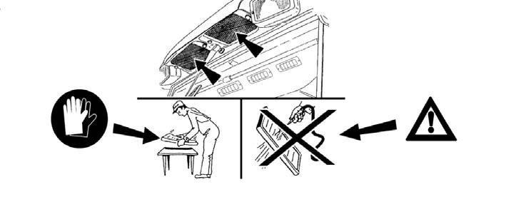
•WARNING: The filter does not provide complete protection from toxic substances
•When handling the filter wear protective gloves
•Do not clean or blow the filter with compressed air.
DANGER: Replace the active carbon filter every 200 hours or 36 months (the production date is printed on the filter). If you feel the smell of pesticides in the cab, replace the filter immediately and have the cab sealing checked. Used filters must be disposed of in specialized collection centres.
When pesticides are sprayed and a heating filter with active carbon is used, the recirculation control must be in the “air suctioned from the outside” position and the fan control in the “maximum” position to create overpressure in the cab.
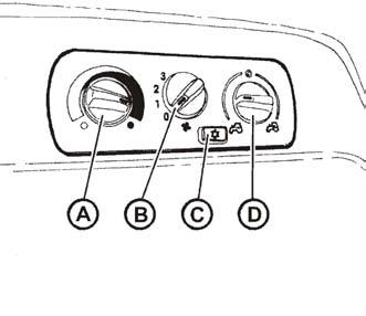
CONTROL PANEL OF HEATING, *AIRCONDITIONING
A -Heating valve control
B -Fan control
C -Air-conditioning switch
D -Control of air circulation in the cab
HEATING VALVE CONTROL (A) a -Heating valve closed b -Heating valve open
FAN CONTROL (B)
0 -Fan off
1 -Slow fan speed
2 -Medium fan speed
3 -Maximum fan speed
*AIR-CONDITIONING SWITCH (C)
The air-conditioning system is switched on and off with the switch with the snowflake symbol (C).
By pressing the switch you will put the air-conditioning system in operation (the snowflake symbol is lit).
You can switch off the air-conditioning system by pressing the switch again (the snowflake symbol is off).
CONTROL OF AIR CIRCULATION IN THE CAB (D)
a -Surrounding (external) air is suctioned to the cab via filters - air suctioning from the cab is closed.
b -Air is suctioned from the inside of the cab and blown into the cab again (air recirculation fast quick adjustment of temperature in the cab). In this position the air inlet from the outside of the cabin is completely closed and in the cabin there is no overpressure that prevents penetration of unfiltered air to the cabin!
Do not use this position of the control during working operation of the tractor!
PROPER FUNCTION OF THE HEATING AND AIR-CONDITIONING SYSTEM
To ensure proper functioning of the heating or air-conditioning system it is necessary to create overpressure in the cab. Therefore, we recommend you to close all the windows, doors and tilting lid of the cabin.
Fast Heating Of The Cab Space
Proceed as follows:
1 - Turn the heating valve control (A) to the right position (heating valve fully open).
2 - Set the control of air circulation in the cab (D) to the internal circulation position.
3 - Use the fan control (B) to select the corresponding fan speed (position 1, 2, 3)
4 - Set the outlets to the required angle to avoid direct blowing of air to the persons in the cab.
5 - After heating of the cab space set the control of air circulation in the cab (D) to the position of suctioning external air - see fig. F_02_17b, position (a).
Quick Cooling Of The Cab Space
Proceed as follows:
1 - Turn the heating valve control (A) to the left position.
2 - Set the control of air circulation in the cab (D) to the position of suctioning external air.
3 - Use the fan control (B) to select the corresponding fan speed (position 1, 2, 3)
4 - Use the switch (C) to switch on the air-conditioning system.
5 - Set the outlets to the required angle to avoid blowing of air directly to the persons in the cabin (possible occurrence of an illness due to intensive cooling of body parts).
HEATING OR AIR-CONDITIONING OPERATION DURING WORK OF THE TRACTOR
When internal air circulation is on, the fresh air inlet is closed and the air in the cab space may be breathed up by the operators. This situation may cause the feeling of tiredness and further due to overpressure loss in the cab dust may penetrate to the cab. Note: During work set the switch (D) in accordance with individual requirements to a temperature in a position between (a) and (b) so that the fan can suction air from the outside via filters.
Immediately After Cooling Down The Cab
Immediately after cooling of the cab and reduction of the internal temperature to the required value we recommend you to:
−Perform smooth regulation of air temperature with the air-conditioning on by partially opening the heating valve (A). At this setting the air entering the cabin from the outlets is not dried so intensively.
−You can also smoothly regulate the air temperature with the air-conditioning on by reducing the fan output by switching the control (B) to position 1 or 2.
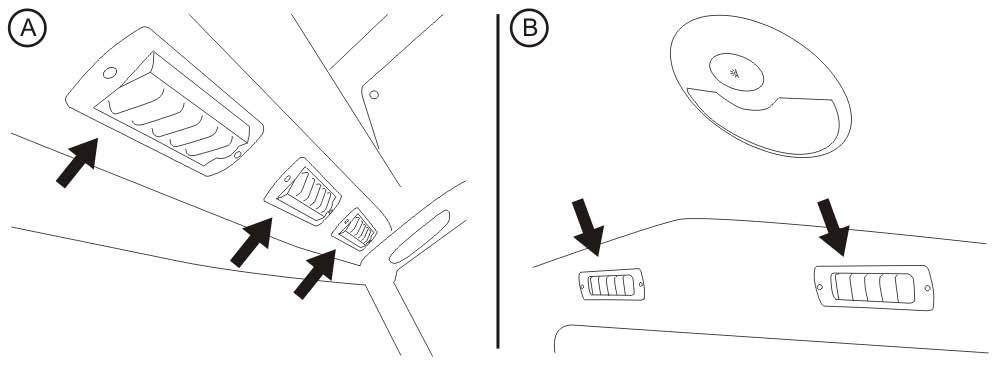
AIR-CONDITION AND HEATING REGISTERS (A)
Positionable heating and ∗ air-condition registers, front (A), rear (B).
FRONT WINDSHIELD (B)
Defrosting
To ensure quick defrosting of the front windshield direct the central heating outlets (1) under the angle of approx. 45° towards the windshield. Direct the side outlets (2) under the angle of approx. 45° to the cab corners.

After defrosting of the front windshield direct the side outlets to the side glasses of the doors as necessary and gradually defrost them. After defrosting direct the outlets in such a way that the air should not be blown directly to the driver, but down to the driver’s legs.
Acquaintance With The Tractor
Tiltable Window
Opens after turning arresting levers of the window (A) and tilting in the direction of arrows.

SUN SCREEN
Sun screen to be drawn out by pulling the ring (B) and locking by hooking the ring by the hook (C).
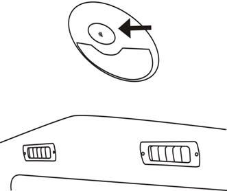
Internal Lighting
To be turned on and off by means of a button marked with the arrow.
Acquaintance With The Tractor
Dashboard Devices Description
A - Indicators
B - Air pressure gauge
C - speedometer
D - fuel gauge
E - coolant thermometer
F - display
Acquaintance With The Tractor
Indicators
1 - High beam lights (blue). Lights up when high beam headlights are on.
2 - Tractor turn signal indicator (green)
3 - 1st trailer turn signal indicator (green)
4 - 2nd trailer turn signal indicator (green)
5 - Indicator of minimum air pressure in the brake system (red). Lights up if the air pressure for the air brakes of the trailer drops below the critical limit, i.e. 450 kPa.
6 - Parking brake (red). Lights up when the parking brake lever is in the “on” position.
7 - Charging. During engine operation it lights up in case of a charging failure. If the engine is stopped, it must light up. For more information see Electrical installation chapter
8 - Lubrication (red). During engine operation it light up if the engine oil pressure drops below 120 to 60 kPa. If the engine is stopped, it must light up.
9 - Air filter clogging indicator (yellow). It lights up with air filter clogging.
10 - Free
11 -indicator of critical temperature of coolant (red) lights up when reaching a temperature of 100°C (disengaged).
12 -Indicator of engagement of multiplier (green – 1st degree).
13 - Indicator of engagement of multiplier (green – 2nd degree).
14 - Indicator of error signalization in the system of hydrostatic steering (red) With engine engaged lights up with failure of hydrostatic steering. If engine is at standstill, it must be lit.
15 - Fuel (orange). It is lit with residue of 1/6 - 1/10 of tank volume.
16 - Indicator of PTO engagement (orange) is not engaged.
17 - Engine glowing (yellow). Signals activity of device for easing the start of engine.
18 - Free
19 - Gearbox disorder control (red), for more see “Driving operation” chapter
20 - Warning indicator (red). Lights up with pressure drop under critical limit i.e. 450 kPa, with engaged parking brake, with charging failure, with low pressure of oil in the engine or with brake lining of the front brake wear off. 21
Acquaintance With The Tractor
Acquaintance With The Tractor
Selectors And Switches
After pressing the selected switch, the applicable symbol and data is displayed on the display.
25 - Battery voltage button: The voltage value is displayed on the display (with the resolution of 0.1 V).
26 - Button of the number of covered kilometres (per day or since the last reset). The number of kilometres is shown on the display. The value can be reset with long pressing of the button.
27 - Button of immediate travel speed in km.h-1, which is displayed on the display.
28 - Free
29 - 1000 rpm PTO button. The rpm value with the resolution of 10 rpm is shown on the display.
Serves only for operation data display
30 - The switch of hours of operation. The information is displayed on the display.
Display Of Pto Speed
By pressing the switch marked with the arrow, you will display the PTO speed in the left and right parts of the display. It is a number of revolutions with engaged PTO independent revolutions.
By pressing the buttons gradually, you will induced the number of PTO revolutions for individual gears of PTO revolutions.

a.for 1000 revolutions b.for 540 revolutions c.for 540E revolutions d.for 1000E revolutions
The button serves only for displaying data.
Acquaintance With The Tractor
SWITCHES, SELECTORS AND LEVERS
a - Light switch (off, parking, main headlights) b - Selector of low beam lights in the tractor grill and working lights on the tractor cab in the roof. c - Fog light switch (off - on). The function of the fog light is indicated by the illuminated symbol on the switch. d - Switch of the working headlight (off-on) The function of the working headlight is indicated by the illuminated symbol on the switch. e - Warning light switch f - Switch of the front driving axle. Engaged front driving axle is indicated by the illuminated symbol on the switch. g - Beacon switch (off - on) h - Switch of the working lights in the tractor grill (off – on) i - Multiplier automatic preselection switch j - Differential lock button k - Switching box l - Selector of turn signal, low and high beam lights and the Selector of turn signal, low and high beam lights and the acoustic and light warning signals

F13BN003
LIGHT SWITCH (A) a - Lights “OFF” b - Sidelights and tail lights, registration sign and instrument lighting “ON” c - All the electric appliances are ON as in position “b” In addition, low or high beam lights are “ON” (depending on the position of the selector of the turn signal, lights and horn)
Switch Of The Front Driving
AXLE (F) a - Front driving axle “OFF” b - Front driving axle “ON”
Use the front driving axle in case the rear wheels slip to increase the traction of the tractor.
Engagement of front drive axle is signalized by a lit symbol on a switch. More in “Driving operation” chapter
WARNING LIGHT SWITCH (E) a - Warning lights “OFF” b - Warning lights “ON”
The function of the warning lights is signalled by intermittent flashing of the indicator on the dashboard.
SELECTOR OF THE GRILL AND CAB
HEADLIGHTS (B) a - Lights in the roof “OFF” b - Lights in the roof “ON”
This selector controls the lights in the grill or roof of the tractor cab. Only use the lights in the cab roof if an implement is attached to the front three-point hitch that covers the headlights in the grill. Switched on lights in the cabin roof are indicated by the illuminated symbol on the switch.
High beam lights are only available in the tractor grill.
FRONT, REAR DIFFERENTIAL LOCK
BUTTON (J) a - Differential lock engaged b - Differential lock disengaged
The differential lock is engaged by pressing of the button, which returns to the original position after being released.
The engagement of the differential lock is indicated by the illuminated symbol on the switch.
The differential lock is automatically disengaged on pressing of the brake pedals.
SELECTOR OF TURN SIGNAL, LOW AND HIGH BEAM LIGHTS AND HORN (L) a - Acoustic horn - push the selector in the axial direction b - Low beam lights c - Right turn signal d - Left turn signal e - Light warning signal f - High beam lights
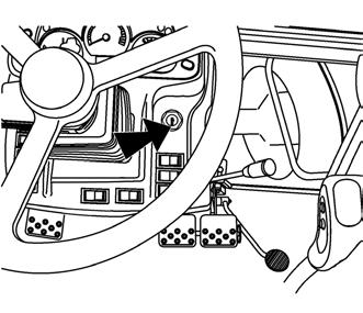
Switching Box
The switching box is located on the dashboard, see arrow.
KEY IN “0” POSITION
The voltage of all appliances controlled via the key is disconnected. The key can be removed.
KEY IN “I” POSITION
Voltage is connected to all appliances except the starter motor. The key is in this position during engine operation.
KEY IN “II” POSITION
In this position the starter motor and all the electric appliances are connected except wipers, washers, cab fan and airconditioning. After starting the key automatically returns to the “I” position.
LIGHTER AND THREE-PIN SOCKET
The lighter (1) and three-pin socket are located on the panel of the right rear fender.
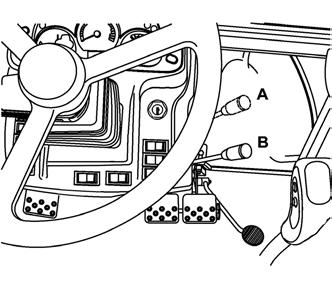
MANUAL THROTTLE LEVER
A - Maximum delivery
B - Idle run
TORQUE MULTIPLIER PRESELECTION SWITCH (I)
a - Preselection switch “OFF” b - Preselection switch “ON”
Position (b) - preselection switch “ON” is indicated by the illuminated symbol on the switch.
If the preselection switch (b) is “ON”, on each pressing of the clutch pedal the medium stage of the multiplier M is automatically engaged - on the dashboard one indicator with the tortoise symbol is lit (see chapter Driving Operation / Indication of the multiplier function of the “Operator’s Manual”)
After releasing of the clutch pedal the multiplier can be controlled with the buttons on the shifting lever.
During engine starting the switch must be in the “OFF” position (a).
Acquaintance With The Tractor
PEDALS AND LEVERS
1 -Travel clutch pedal
2 -Foot brake pedals connected with a latch
3 -Foot throttle pedal
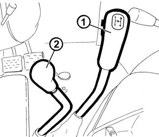
MAIN SHIFTING LEVER AND REVERSING LEVER
1 -Main shifting lever with three-stage multiplier control buttons
2 -Reversing lever
SHIFTING LEVER OF ROAD AND REDUCED GEARS
The lever is located at the left side of the driver’s seat.

H - - Road gears
N - Neutral
L - - Reduced gears
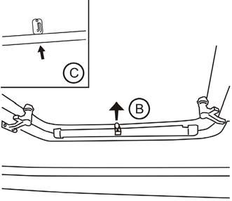
PRESELECTION OF STANDARD AND ECONOMIC REAR PTO SHAFT REVOLUTIONS LEVER
The lever is placed on the right side of driver’s seat. After shifting the lever it is necessary to lift the collar in the direction of the arrow (C).
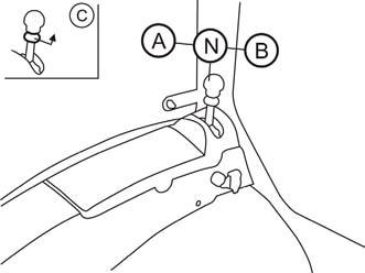
AStandard PTO shaft revolutions engaged
NNeutral position
The ending of rear PTO shaft can be spun freely
BPTO shaft economic revolutions engaged
LEVERS OF THE PARKING BRAKE AND HITCH FOR A SINGLE-AXLE TRAILER
1 - Parking brake lever a - Unbraked b - Braked
2 - Hitch control lever for a single-axle trailer a - Transport position b - Carrying hooks tilted off, the pulling hook with the carrier can be lowered
HYDRAULIC CONTROL PANEL
It is located in the area of the right fender.
You will find a detailed description of the control and functions in the “Hydraulic system” and “Electro-hydraulic system” chapters of this Operator’s Manual.
CONTROL OF THE AUXILIARY HYDRAULIC DISTRIBUTOR (EXTERNAL HYDRAULIC CIRCUIT)
It is located on the upper part of the right fender.
You will find a detailed description of the control and functions of the integrated hydraulic distributor (external hydraulic circuit) in the "Hydraulic system" chapter of this Operator's Manual.
Control Panel On The Right
CAB PILLAR
1 -rear PTO shaft engagement
2 -front PTO shaft engagement
3 -two-position switch of front wiper and front windshield washer control
4 -rear wiper switch
5 -switch of front working lights on the roof of the cabin
6 -switch of rear working lights on the roof of the cabin
7 -rear mirrors heating *switch
8 -rear window heating *switch

9 -rear PTO shaft revolutions switch
Battery Disconnector
In case of long periods of inactivity, repairs, failures or an accident immediately disconnect the battery with the battery disconnector, which is found at the left side of the tractor.

1 -Battery disconnected
2 -Battery connected
F11N091
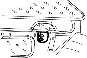
Aggregation Opening
Aggregation opening serves for placing cabling or bowden controls of aggregated implement.
By pulling extend the part of the rear window sealing upwards. Stick the control of the aggregated implement through the originated opening. Insert the controls of the cablings or bowdens to openings of penetration of the aggregated opening. Return the sealing of the rear window to the original position.
Fuel Tank
All the tractor types are equipped with a plastic fuel tank with the volume of 180 l as standard.
Do not step on the fuel tank!
Drain Plug Of The Fuel Tank
The hole for draining dirt and fuel from the fuel tank is found in its bottom.
Before driving the new tractor first get acquainted with the gear shifting pattern and test individual positions of the shifting lever at the engine standstill.
Also check whether the technical condition corresponds to traffic safety requirements.