12 minute read
ASSEMBLY


A WARNING
Before working underneath, raise mower to
highest position and block securely. Blocking up prevents mower dropping due to hydraulic leak down, hydraulic system failures, or mechanical component failures.
Always wear relatively tight and belted clothing
to avoid getting caught in moving parts. Wear sturdy, rough-soled work shoes and protective equipment for eyes, hair, hands, hearing, and head; and respirator or filter mask where appropriate.
A CAUTION
DEALER SET-UP INSTRUCTIONS
Assembly of the mower is the responsibility of the WOODS dealer. It should be delivered to the owner completely assembled, lubricated, and adjusted for normal conditions. The following instructions apply to the assembly of both the RM990-3 and the P990-3, unless otherwise noted. Complete the checklists on page 40 when assembly is complete.
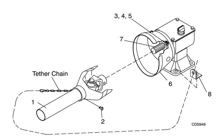
1. Driveline 2. Shield Retainer 3. Screw, HHCS 5/16" x 3/4 4. Screw, HHCS M8 x 1.25 x 20 5. Washer, 5/16" Standard 6. Counter-Cone Shield 7. Gearbox Output Shield 8. Tether Chain Bracket
NOTICE
■ Gearbox was not filled at factory. It must be
serviced before operating mower. Failure to service will result in damage to the gearbox. See page 16.
The mower is shipped partially assembled. Assembly will be easier if the components are aligned and loosely assembled before tightening hardware. Recommended torque values for hardware are located on page 67. Select a suitable working area. Open parts boxes and lay out parts and hardware to make location easy. Refer to illustrations, accompanying text, parts lists and exploded view drawings.
Rear Driveline Installation
RM990 Only
Attach counter-cone shield (6) over gearbox output shield (7) using four 5/16" cap screws (3) OR M8 cap screws (4) and lock washers (5). See Figure 26. Attach implement end of driveline (1) to gearbox output shield (7). Fasten tether chain to bracket (8) as shown, securing with left front gearbox mounting bolt. Chain must be loose enough to allow full joint articulation.
Figure 26. Rear Driveline Installation - RM990
1. Rear drive shield 2. Driveline 3. Retaining ring (SN 788882 and prior) 4. 1/2" Hex lock nut (SN 788882 and prior) 5. 1/2 x 3" Shear bolt (SN 788882 and prior) 6. Gearbox input shaft 7. Left drive shield bracket 8. Gearbox shield 9. Right drive shield bracket 10.3/8 x 1" Bolt (SN 788882 and prior) 10.M8 x 1.25 x 25 Bolt (after SN 788882) 11.3/8" Lock washer 12.3/8" Flanged nut 13.Tether chain 14.Tether chain bracket

Figure 27. Rear Driveline Installation - P990
P990 Only
Remove drive shield (1) from the driveline. Place the yoke horizontally in a vise. Firmly pull shield backward while pushing each of the three bearing tabs down to release them. See Figure 27. To prevent gearbox seal damage, carefully push driveline yoke onto gearbox input shaft until it contacts the housing. Install retaining ring (3) and pull driveline forward. Align driveline yoke and gearbox input shaft holes and install shear bolt (5). Then install and tighten nut (4). Install drive shield (1) by aligning the three shield holes with the three bearing tabs and pushing shield on firmly to ensure the bearing tabs all engage. Remove both front gearbox top cover bolts and lock washers (10 & 11). Place left and right drive shield brackets (7 & 9) on gearbox top cover and secure with bolts and lock washers (10 & 11). Attach gearbox shield (8) to shield brackets with flanged nuts (12). Fasten tether chain (13) loosely (allowing greatest joint articulation) to bracket (14) on left front gearbox mounting bolt.
13
1. 5/8 x 3-1/2" Bolt 2. 5/8" Flat washer 3. .64 x 1.00 x 2.09" Sleeve 4. Hitch pin bracket 5. A-frame bar 6. Category 1 mounting pin 7. 5/8" Hex nut 8. 1/2 x 6" Bolt 9. 3-Point brace bar 10.1/2 Schedule 40 x 2-3/4" pipe 11.Top link clevis 12.1/2" Flanged hex lock nut 13.PTO Hanger bracket

Figure 28. RM990-3 Hitch Installation
RM990-3 HITCH INSTALLATION
(Figure 28)
The RM990-3 is shipped with Category 1 hitch pins in the shipping location. Remove bolt (1) and hitch pin bracket (4). Remove the hitch pin (6) from the shipping location and place it in the end hole. Insert the hitch pin bracket (4) into the mast plate as shown. Slide sleeve (3) through holes flush with outside of mast plate and secure with bolt (1), washers (2), and hex lock nut. Repeat for other side. Remove bolt (8) and assemble 3-point brace bars (9) on outside of A-frame bars (5). Re-install bolt (8) through bars, spacer and top-link clevis (11). Tighten all hitch assembly hardware. (See torque chart in Operator’s Manual.) Install PTO hanger bracket (13) to upper mast assembly. Secure with flange lock nut (12). Do not overtighten lock nut. PTO hanger bracket should be able to rotate freely out of the way when the mower is in operation.
1. Wheel yoke assembly 2. Attitude rod 3. 1-1/4 x 3-1/4" Pin 4. 1-5/16 x 1-3/4 x 2-1/8" Sleeve 5. 3/4 x 3/4" Pipe 6. 3/4" Lock nut 7. Ratchet 8. 5/8 x 2" Bolt 9. 5/8 Hex lock nut GR5 10.5/8 Flat washer

Figure 29. P990-3 Wheel Yoke Installation
P990-3 Wheel Yoke Installation
Remove tongue from wheel yoke. See Figure 29. Loosen the nuts on bolts (8) and pivot the wheel yoke (1) to the rear. Install bolt (8) in each mounting bracket and flat washers (10), secure nut (9). Tighten the hardware.
P990-3 Attitude Rod and Height Adj. Installation
Place sleeve (4) between attitude rod lugs on wheel yoke. Insert pin (3) through sleeve (4) and align the holes. Insert attitude rod (2) through these holes. See Figure 29. Place pipe spacer (5) over attitude rod (2) and start lock nut (6) on rod.
P990-3 Tongue & H-Frame Installation
Place washer (17) and sleeve (18) on bolt (16). See Figure 30. Place tongue assembly (1) into mast plates on mower frame and insert bolt, washer and sleeve assembly to hold in place. Repeat for opposite side. Place an additional washer (17) on bolt (16), then a lock washer (19) and nut (20). Repeat for opposite side and tighten hardware. Attach parking jack (21) to tongue (1) as shown. Install ratchet adjustment link (7) between the tongue and height adjustment post on wheel yoke using pins provided with adjustment link. The optional hydraulic cylinder may be installed in place of the adjustment link (7). Connect attitude rod (5) to tongue (1), as shown, with clevis pin (15) and cotter pin (6). Attach H-frame (2) to tongue (1), as shown, with clevis pin (7) and two cotter pins (6). Apply grease to all sides of rear driveline and slide the rear portion of the front driveline (25) onto it. Attach carrier bearing housing (3) into a set of H-frame adjustment holes with clevis pin (8) and cotter pin (6). Final adjustment will be required when mower is attached to tractor. Attach front drive shield (4) to carrier bearing housing (3) with bolts (13) and lock washers (14). Place spacer (11) between H-frame as shown and secure with bolt (12), lock washer (10) and nut (9). Attach driveline shield tether chains (23 & 24) to Hframe (2). Front tether chain (22) will be attached to tractor.
1. Tongue assembly 2. H-Frame 3. Carrier bearing housing 4. Drive shield 5. Attitude rod 6. 3/16 x 1" Cotter pin 7. 5/8 x 5-21/32" Clevis pin 8. 1/2 x 5-3/4" Clevis pin 9. 1/2" Heavy hex nut 10. 1/2" Heavy lock washer 11. 1/2 x 3-9/16" Pipe 12. 1/2 x 5-1/2" Bolt 13. 3/8 x 1" Bolt 14. 3/8" Lock washer 15. 5/8 x 2-1/4" Clevis pin 16. 5/8 x 3-1/2" Bolt 17. 5/8" Flat washer 18. .64 x 1 x 2" Sleeve 19. 5/8" Lock washer 20. 5/8" Hex nut 21. Parking jack 22. Front tether chain 23. Middle tether chain 24. Rear tether chain 25. Driveline

Figure 30. P990-3 Tongue & H-Frame Installation
1. Right rear shield assembly 2. Left rear shield assembly 3. 3/8 x 1" Carriage bolt 4. 3/8" Flanged hex lock nut 5. Left front shield assembly 6. Right front shield assembly
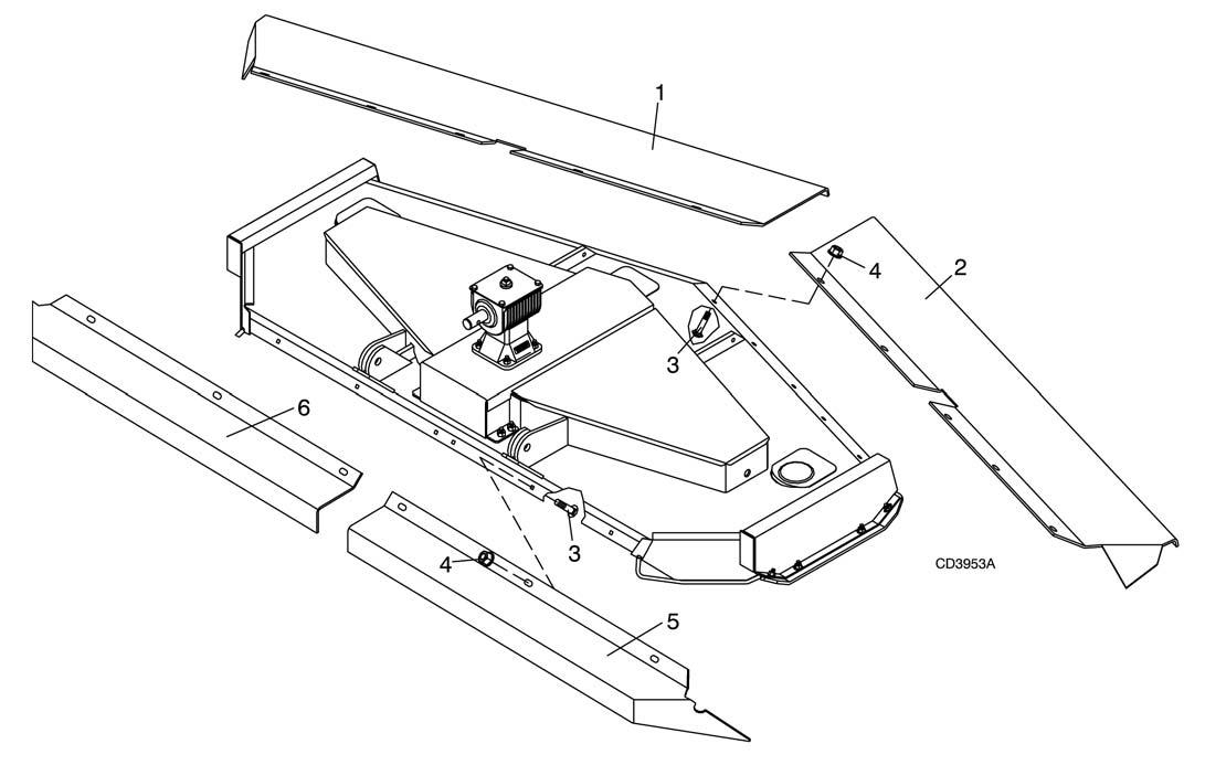
Figure 31. Chain Shielding Installation
Chain Shielding Installation
Chain shielding is assembled. Attach to mower as shown. See Figure 31.
OPTIONAL EQUIPMENT INSTALLATION Optional Hydraulic Cylinder and Standard Transport Bar Installation for P990-3
A CAUTION
Your dealer can supply original equipment
hydraulic accessories and repair parts. Substitute parts may not meet original equipment specifications and may be dangerous.
The transport bar, which is shipped as standard equipment, must be installed when the optional hydraulic cylinder is used to replace the ratchet adjustment link. Do not operate mower unless either the ratchet adjustment link or the optional hydraulic cylinder and transport bar is installed. Install cylinder rod clevis over wheel yoke height adjustment lug and insert clevis pin (3). Place a flat washer (5) over each end of clevis pin. Place transport bar (2) over clevis pin (3) on right side of cylinder clevis, then place another flat washer (5) over pin and secure with cotter pins (4) in each end of clevis pin. Attach butt end of cylinder to tongue with clevis pin and retainer clips provided with cylinder. To engage transport bar, raise mower to the highest position and pivot the transport bar over the hydraulic cylinder rod. Install lock pin through transport bar clevis, beneath hydraulic cylinder rod.
1. 3-1/2 x 8" Single-acting hydraulic cylinder 2. Transport bar 3. Lock-up pin 4. 1/4 x 1-3/4" Cotter pin 5. 1 x 2" x 10 GA Flat washer 6. 3/16" Safety pin
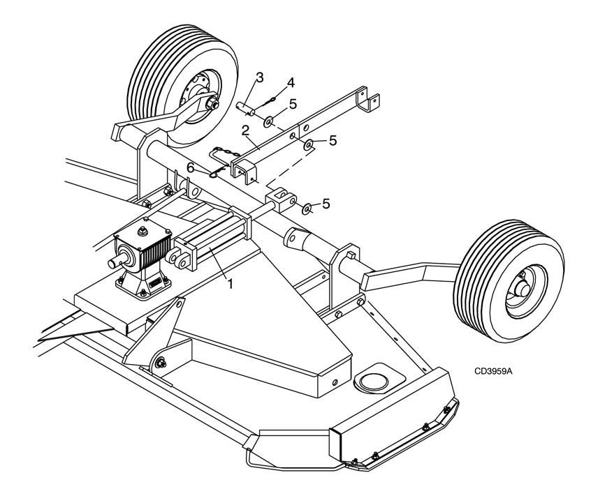
Figure 32. Optional Hydraulic Cylinder Installation for P990-3
Front Gauge Roller Installation for RM990-3 and P990-3 (Figure 33)
Optional front gauge rollers are designed to carry front corners of the mower over uneven ground, minimizing gouging and scalping. Front gauge roller mounting points are provided on both front mower frame corners. The gauge roller and mounting bracket are pre-assembled. Attach the gauge roller assembly (1) to corner of mower frame by installing carriage bolts (3) from inside the mower frame as shown. Secure with flange lock nuts (2). Repeat for opposite gauge roller. 1. Front gauge roller assembly 2. 1/2" Flanged hex lock nut 3. 1/2 x 1-1/4" Carriage bolt

Figure 33. Optional Front Gauge Roller Installation
The optional front roller is designed to carry the center of the mower over uneven ground, minimizing scalping. Front roller mounting brackets use the four mounting bolts of the gear stand. Remove the gear stand front mounting bolts. Hole patterns in the mounting brackets (1 & 2) determine right and left. Position these brackets with the highest hole to the rear, the middle hole forward, and the bracket angle outward as shown. Attach brackets with the carriage bolts (3) and flange lock nuts (7) provided with the front roller kit. Place roller (5) between the brackets and insert rod (6) through brackets and roller, securing with cotter pins (4).
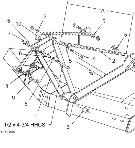
1. Right bracket 2. Left bracket 3. 3/8 x 1" Carriage bolt 4. 3/16 x 1" Cotter pin 5. Front roller 6. Rod 7. 3/8" Flanged lock nut 1.Offset Link 2.38-Link Chain 3.0.91 Sleeve 4.1/2" x 6 Cap Screw 5.1/2" Flat Washer 6.0.5 Sleeve 7.1/2" Flange Lock Nut 8.7/8" Sleeve 9.7/8" Flat Washer 10..81x1.25x1.81 Sleeve
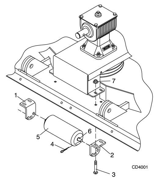
Figure 34. Optional Front Roller Installation Figure 35. Quick Hitch Kit Assembly (RM660 Shown; Other units use same instructions) Note: This kit allows mower to fit only Cat. 1 standard ASAE quick hitch. Attach offset link (1) to mounting pins, using 7/8 sleeve (8) and flat washer (9). Attach upper end of offset link to pivot link, using 1/2 flat washer (5), sleeves (6 & 10), flange lock nut (7), and 1/2 x 4-3/4 cap screw. Remove rear offset links and replace with chains (2). Cut to required length. Attach chain to top of A-frame as shown, using 1/2 x 6 cap screw (4), 1/2 flat washer (5), and nut. Attach opposite end of chain (2) to rear mower frame as shown. Cut chain to 45 inches in length. Vary length slightly as desired. Twist chain to make finite adjustments in length until unit lifts level. Do not bottom out the drive on front of deck.
NOTICE
■ Failure to follow instructions may result in
damage.
Install sleeve (3) on mounting pins and retain with Klik pin.
Remove the front caster wheel and arm assemblies from shipping location along the outer deck rails. Attach adjustment lugs to frame with bolts (16) and nuts (18). Attach caster wheel arm to frame with bolt (20) and nut (22). The wheel comes assembled with bearings and cups installed. Adjust mower cutting height by using chart (page 11) and nut (18). Tighten all hardware (see Bolt Torque Chart). Repeat for opposite front caster wheel.
1. Wheel assembly 3. Support plate 4. Caster wheel arm 8. Caster yoke 15.Grease zerk 16.1/2" x 3-3/4 Cap screw 18.1/2" Flanged nut 20.5/8" x 4 Cap screw 22.5/8" Flanged nut 1. Support plate 2. Caster wheel arm 12.Tire 13.Caster yoke 32.1/2" x 3-3/4 Cap screw 34.1/2" Flange lock nut 36.5/8" x 4 Cap screw 38.5/8" Hex nut

Figure 36. Front Caster Wheel Installation Rear Caster Wheel Installation for RM990-3
Remove the rear caster wheel and arm assemblies from shipping location along the inner deck rails. Discard the shipping bolts. Attach adjustment lugs to frame with bolts (36), lock washers (37) and nuts (38). Attach caster wheel arm to frame with bolt (36), lock washer (37) and nuts (38). The wheel comes assembled with bearings and cups installed. Adjust mower cutting height by using chart (page 11) and secure with bolts (32) and nuts. Tighten all hardware (see page 67). Repeat for opposite rear caster wheel.

Figure 37. RM990-3 Rear Caster Wheel Installation
Initial Filling of Gearbox NOTICE
■ Gearbox was not filled with oil at the factory. It
must be serviced before operating. Failure to service will result in damage to gearbox.
The gearbox was not filled at the factory. Remove the fill plug and pour in one quart of SAE 90W gear lube, wait five minutes and add an additional pint and one half. Allow an additional five minutes for the lube to flow through the bearings, then check to make sure half of the horizontal gear shaft is covered. Replace the fill plug.