19 minute read
DEALER SERVICE


The information in this section is written for dealer service personnel. The repairs described require special skills and tools. If your shop is not properly equipped or your mechanics are not properly trained in this type of repair, you may be time and money ahead to replace complete assemblies.
A WARNING
Before servicing, adjusting, repairing or unplug-
ging, stop tractor engine, place all controls in neutral, set park brake, remove ignition key, and wait for all moving parts to stop.
Keep all persons away from operator control
area while performing adjustments, service, or maintenance.
Make certain all movement of equipment com-
ponents has stopped before approaching for service.
Always wear relatively tight and belted clothing
to avoid getting caught in moving parts. Wear sturdy, rough-soled work shoes and protective equipment for eyes, hair, hands, hearing, and head; and respirator or filter mask where appropriate.
A CAUTION
BLOCKING METHODS
Jack stands, with a load rating of 1,000 pounds or more, are the only approved blocking device for this mower. A minimum of four jack stands, located under the mower as shown in Figure 14, must be installed before working underneath this unit. Do not position jack stands under wheels, axles, or wheel supports because these components can rotate. Do not work underneath unless it is properly attached to tractor (see Operation Section), the brakes set, key removed, and the mower blocked securely. The mounted unit will be anchored to minimize side to side and front to rear movement. The pull-type unit will be anchored front to rear. For the mounted unit, tighten tractor lower 3-point arm anti-sway mechanisms to prevent side to side movement. For the pull-type unit, raise mower with the standard ratchet adjustment link or the optional hydraulic cylinder. When the optional hydraulic cylinder is installed the standard equipment transport bar must be pinned in the raised position. With either the ratchet adjustment link or the optional hydraulic cylinder, lower the mower to transfer its weight to the jack stands, but do not raise the rear wheels off of the ground. When blocking, you must consider overall stability of the unit. Just placing jack stands under the unit will not ensure your safety. The working surface must be level and solid to support the weight on the jacks stands. Ensure jack stands are stable both top and bottom, and mower is approximately level. With full mower weight lowered on jack stands, test blocking stability before working underneath mower.
Figure 14. Jack Stand Placement (Tractor and Connection Not Shown)
BLADE SPINDLE Blade Spindle Repair Tips
As a reference point, the grease fitting is in the top portion of the spindle housing. To minimize wear, the bearing cups, cones and sleeves are press fit to the shaft and will require a press or similar device for removal. When disassembling, support housing casting to prevent damage. Remove bearing cups by placing a punch in housing slots and driving cup out. Alternate punch positions from side to side. Use care to prevent housing damage. Permatex 3-D Aviation Form-A-Gasket® or equivalent is recommended as a sealant for spindle repair.
Blade Spindle Removal
Remove belt. Remove blades from spindle. Remove bolt and washer from top of spindle shaft. Remove split taper bushing (located on top of pulley) by removing the two bolts and inserting them into the threaded holes in bushing flange. Tighten alternately to remove split taper bushing.
Remove key and pulley. Remove the four bolts and nuts attaching spindle to mower frame and remove spindle. Store bushing, pulley and all hardware for reinstallation.
1. Blade Spindle Complete 2. Sleeve 3. Seal 4. Bearing Cone 5. Spindle Housing with Cups 6. Bearing Cup 7. Grease Fitting 8. Flat Washer 9. Spindle Shaft and Crossbar 10. Blade Lock 11. QD Blade Pin 12. 1/2 x 3/4" Nylock Bolt 13. Blade

Figure 15. Blade Spindle Assembly
Blade Spindle Disassembly
Support housing and press blade carrier and shaft (9) out. Remove seals, bearing cones and cups from housing. See Figure 15. Bearing cups and cones are designed to work together. It is important to position them so bearing cone taper mates with bearing cup taper. See Figure 15. Lubricate new cups (6) with a light oil. Place them in spindle housing (5) so they will mate with cones (4). Seat cups (6) against machined shoulder of housing with a press or by placing a large soft drift on the flat lip and driving them into housing. Pack bottom bearing cone (4) with grease and place it into housing against bearing cup (6).
NOTICE
■ Bearing failure is often a result of improper seal
installation and positioning. Follow instructions carefully.
Lightly coat housing area where seals seat with Permatex or equivalent. Lightly lubricate seal, locate spring and place seal squarely on housing with spring toward housing center. Select a pipe or tubing with an outside diameter that will set on outside seal edge. One that is too small will bow seal cage. Carefully press seal into housing, preventing distortion to metal seal cage. Seal should seat firmly and squarely against machined housing shoulder. Make sure seal lip did not roll under. Distortion to seal cage or seal lip damage will cause leakage. Damaged seals must be replaced. Place housing assembly over shaft and blade center (9) and carefully guide over shaft while pressing shaft into bearing cup and cone. Assembly should seat firmly against step in shaft. Fill housing cavity with a lithium grease of No. 2 consistency with a MOLY (molybdenum disulfide) additive. Pack top bearing cone (4) with grease and place it (taper down) on shaft. Place sleeve (2) on shaft and press bearing onto shaft until free play is removed and there is a slight drag (similar to adjusting automobile wheel bearings). Check by turning housing on shaft; it should turn freely.
NOTICE
■ Bearing adjustment is set by pressing sleeve
against bearing until proper adjustment is attained. Adjustment is maintained by seating split taper bushing against sleeve.
Adjusting bearings too tightly will shorten their life. Should you overtighten them, hold housing and rap top of shaft with a lead hammer to loosen bearings. Adjust to obtain proper setting.
Proper bearing adjustment is essential to good bearing life. Lightly lubricate top seal, locate spring and place seal squarely on housing with spring up away from housing. Follow installation instructions given for bottom seal. Top seal should be flush with, to 1/16" above, housing.
Blade Spindle Installation
Insert spindle through bottom of mower, positioning grease fitting outward on outer spindles and to the rear on center spindle. Secure to deck with four bolts and flange lock nuts. Place belt pulley over spindle shaft and seat split taper bushing against spindle sleeve. Place flat washer and bolt into threads of spindle shaft and torque to 35 lbs-ft. Place split taper bushing bolts into threaded holes of pulley and tighten alternately to 12 lbs-ft., securing pulley to bushing. Reinstall blades and belt.

WHEEL SPINDLE REPAIR (For Pull-Type Mowers Only)
Wheel spindle repair is accomplished in a manner similar to blade spindle repair. Refer to the wheel spindle parts list and apply the repair techniques outlined in Blade Spindle Disassembly and Assembly (page 23). Adjustment is set and maintained with the slotted hex nut and cotter key.
UNIVERSAL JOINT REPAIR
Two different style driveline U-joints are used. The repair procedure is basically the same. One has internal snap rings (Figure 16); the other has external snap rings (Figure 17). Determine which type you are repairing and remove all four snap rings. 1. Yoke 2. Journal Cross 3. Seal 4. Snap Ring 5. Cup and Bearings 6. Yoke
Figure 16. U-Joint Exploded View with Internal Snap Rings

1. Yoke 2. Cup and Bearing 3. Snap Ring 4. Journal Cross
Figure 17. U-Joint Exploded View with External Snap Rings
1. Remove snap rings from inside or outside of yokes in four locations. (Figure 18 only shows the style with internal snap rings.)
Figure 18. 2. With snap rings removed, support drive in vise, hold yoke in hand and tap on yoke to drive cup up out of yoke. See Figure 19.
Figure 19
3. Clamp cup in vise as shown in Figure 20 and tap on yoke to completely remove cup from yoke.
Repeat steps two and three for opposite cup. Figure 20. 4. Place universal cross in vise as shown in Figure 21 and tap on yoke to remove cup. Repeat step three for final removal. Drive remaining cup out with a drift and hammer.
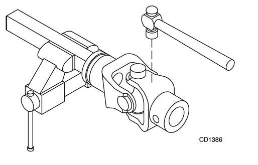
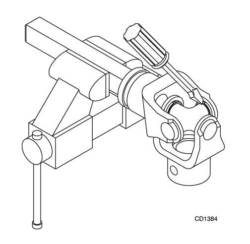
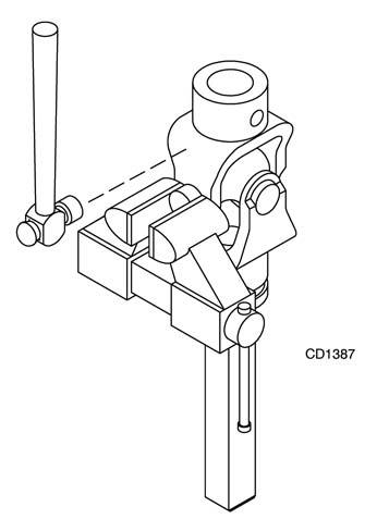
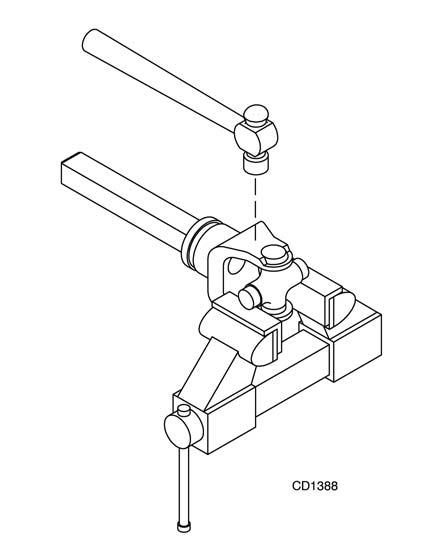
Figure 21.
1. Place seals securely on bearing cups (on internal snap ring style only).
Insert cup into yoke from outside and press in with hand pressure as far as possible. Insert journal cross into bearing cup with grease fitting away from shaft. Be careful not to disturb needle bearings.
Insert another bearing cup directly across from first cup and press in as far as possible with hand pressure.
Trap cups in vise and apply pressure. Be sure journal cross is started into bearings and continue pressure with vise, squeezing in as far as possible.
Tap yoke to aid in process. 2. Seat cups by placing a drift or socket (slightly smaller than the cup) on cup and rapping with a hammer. See Figure 22. Install snap ring and repeat on opposite cup. 3. Repeat steps one and two to install remaining cups in remaining yoke.
Move both yokes in all directions to check for free movement. Should movement be restricted, rap on yokes sharply with a hammer to relieve any tension. Repeat until both yokes move in all directions without restriction.
Figure 22.

GEARBOX MAINTENANCE
Read all of this section before starting any repair. Many steps are dependent on each other. Check gearbox for leakage and shaft side and end play. If excessive shaft play is found, disassemble gearbox and inspect bearings and shafts. Leakage can occur at top cover and at shaft seals. Leakage problems should be corrected immediately to prevent damage to drive belt from gearbox oil. Always clean any spilled lubricant with a cloth moistened with a non-flammable, non-toxic degreasing agent or commercial detergent and water. Be sure to clean pulley grooves. The sealants recommended for gearbox repair are Permatex Aviation 3D Form-A-Gasket® or Loctite 515 Gasket Eliminator® .
Leakage Repair
To repair top cover leakage, clean top cover and housing sides, then remove cover. Remove old sealant from cover and housing. Apply sealant to top cover and replace. Retorque housing bolts. Horizontal seal leakage should be repaired by replacing the seal. The gearbox should be removed from the mower to accomplish this. Remove old seal with care to prevent damage to seal bore and shaft. Sealant should be applied to the seal bore before installing the new seal. The new seal should be seated squarely in the bore against snap ring. Press seal into place with a piece of pipe or tubing that sets against the outside edge of the seal. Tubing with an outside diameter that is too small will bow seal cage and ruin the seal.
Removing Gearbox from Mower
Remove belt and driveline shields. Remove rear driveline shield bearings and remove shield. Remove snap ring from gearbox shaft. Remove shear bolt from end yoke and remove driveline. Remove drive belt from drive sheave. Remove gear stand from mower. Remove drive sheave from mower by removing bolts from split taper bushing and turning them into threaded holes on bushing flange. Tighten evenly, forcing the bushing and drive sheave apart. Remove gearbox from gear stand.
Gearbox Disassembly
(S/N 788882 and prior, Figure 23)
NOTE: A five ton press will be required for vertical gear shaft removal. Remove top cover (12) and drain all gear lube. Clamp gearbox upside-down in a large vise. Place a long 1/2" rod or punch through the horizontal shaft shear bolt hole to prevent shaft rotation. Remove stake
nut (19). If nut is too tight to remove with a spanner wrench, loosen with a punch and hammer. Carefully remove vertical shaft seal (18) to prevent damage to shaft threads and seal bore. Remove gearbox from vise. Use care when removing horizontal shaft seal (1) and retaining ring (2) to prevent damage to shaft seal surface and housing bore. Place puller (20) over horizontal shaft (6) and insert a 1/2" bolt or rod through horizontal shaft shear bolt hole. Tighten puller bolts evenly to remove shaft from housing. Place housing upside-down in a press and remove vertical shaft (14) by pressing through the top of the housing. Remove bearing cone (15) from vertical shaft (14) with a spreader. Remove all cups from housing with a puller or by carefully driving them out with a punch. Inspect gears for excessive wear. Gears are forged and surfaces will appear rough, even when new. Some wear is normal. Gears will show more wear on the loaded side and the pattern should be smooth. Inspect both gear shafts and stake nut for grooves, nicks or bumps where seals seat. Replace if damage cannot be repaired by resurfacing with emery cloth. Clean gearbox housing and inspect for damage. Replace if cracks are found.
Gearbox Assembly
(S/N 788882 and prior, Figure 23)
Press cups (8 & 16) into housing until they seat tightly against machined shoulders. Press bearing cone (15) onto vertical gear shaft (14) and seat it against gear. Insert vertical gear shaft into housing. Invert housing in a press and place supports under gear to hold bearing cone (15) against cup (16). Press bottom bearing cone (15) onto shaft until all free play is removed and there is a slight drag when rotating housing on shaft (similar to setting automobile front wheel bearings). If bearings are too tight, loosen by holding housing and rapping on end of vertical gear shaft (14) with a shot hammer or equivalent. Install O-ring (17) into groove on vertical gear shaft (14) next to bearing cone (15). Place a small bead of gasket sealer on top of O-ring. Use the proper size tubing to press against the outside edge of seal to prevent seal damage. Apply gasket sealant to seal bore and press output shaft seal (18) into housing until it seats against housing shoulder. Coat inner portion of seal with grease. Thread stake nut (19) onto shaft (14) in through seal (18). Tighten until nut is snug against bearing cone (15). Use a punch to stake the lip of stake nut (19) into shaft (14) keyway. Insert shaft (6) through top of housing out through horizontal hole, then set bearing (7) into cup (8). Press bearing (5) onto gear shaft (6). Do not use excessive force to seat bearing. Place bearing cup (4) over horizontal shaft (6) and press into housing until there is a slight drag on bearings when shaft is rotated (similar to setting automobile front wheel bearings). When you have bearings adjusted, select shims from shim kit (3) and place on top of bearing cup (4) until they are flush with bottom of snap ring groove in horizontal shaft (6), then install snap ring (2). Apply gasket sealant to housing seal bore and press seal (1) into housing until it seats against snap ring or is flush with housing. Apply gasket sealant to top of housing flange, replace top cover and secure with bolts (10) and washers (9). Attach gearbox to gear stand and torque mounting bolts. Remove the dipstick and pour in one quart of gear lube. Wait five minutes and add an additional pint and one half. Allow an additional five minutes for the lube to flow through the bearings, then check to make sure half of the horizontal gear shaft is covered. Replace the dipstick.
1. 1.38 x 2.56 x .38" Seal 2. Retaining ring 3. Shim washer kit 4. Bearing cup 5. Bearing cone 6. 30-Tooth gear and horizontal shaft 7. Bearing cone 8. Bearing cup 9. 3/8" Lock washer 10. 3/8 x 3/4" Bolt 11. 1" Vented pipe plug (used prior to S/N 2000) 12. Gearbox cover 13. Housing 14. 17-Tooth gear and vertical shaft 15. Bearing cone 16. Bearing cup 17. O-Ring 18. Double lip seal 19. Stake nut 20. Puller 21. Puller bolts 22. Dipstick (used on SN 2000-788882) 23. O-Ring (used on SN 2000-7888882)

Figure 23. Gearbox Assembly (SN 788882 and Prior)
Gearbox Disassembly
(Units after S/N 788882, Figure 24)
Remove gearbox from cutter as follows: Disconnect and remove the rear driveline from the gearbox. Remove vent plug (27) and siphon gear lube from housing through this opening. Remove cotter pin, washer, and nut from vertical shaft and remove crossbar. Remove the four bolts that hold the gearbox on the cutter. Remove 3/8" plug from side of gearbox and pour out gear oil. Remove oil cap (23) (to be replaced), snap ring (12), and shim (15) from input shaft (3). Support gearbox in hand press and push on the input shaft (3) to remove bearing (9) and spacer (14). Remove top cover (25) from housing and gear (1) from inside housing. Remove oil seal (22) from front of housing (to be replaced). Remove snap ring (12) and shim (15) from front of housing. Support housing in vise in a horizontal position. The castle nut (17), cotter pin (28), washer (18), and hub (24) are already removed with the stump jumper/crossbar. Remove the snap ring (10), washer (19), and seal (21). Remove cotter pin (11), castle nut (16), and washer (20) from output shaft (4). Remove output shaft by using a punch and hammer; tap on the top to drive down. Remove gear (5) and shim (15) from inside housing. Remove bearing (7) by using a punch and hammer
from the top, outside the housing. Support housing upside down (top cover surface) and remove bearing (6) by using a punch and hammer from the bottom side of the housing. Inspect gears for broken teeth and wear. Some wear is normal and will show on loaded side. Forged gear surfaces are rough when new. Check that wear pattern is smooth. Inspect vertical and horizontal shafts for grooves, nicks, or bumps in the areas where the seals seat. Resurface any damage with emery cloth. Inspect housing and caps for cracks or other damage.
1. Crown gear 2. Gearbox housing 3. Input shaft 4. Output shaft 5. Gear pinion 6. Bearing cup & cone 7. Bearing cup & cone 8. Bearing cup & cone 9. Ball bearing 10.Internal retainer ring 11.Cotter pin 12.Snap ring 13.Snap ring 14.Spacer 15.Shim kit 16.Castle nut 17.Castle nut metric M24 x 2 18.Protective washer 19.21 x 37 x 3 Washer 20.25 x 48 x 2.5 Washer 21.Metric seal 40 x 80 x 12 22.Oil seal 23.Oil cap 25.Top cover 26.M8 x 16 Bolt 27.Vented plug
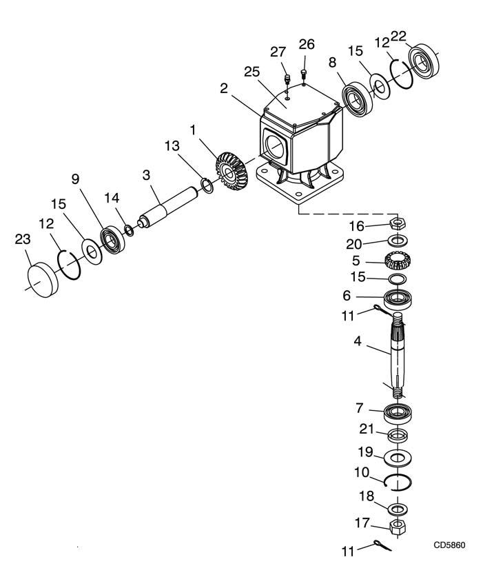
Figure 24. Gearbox Assembly (After SN 788882)
Gearbox Assembly
(Units after SN 788882, Figure 24)
NOTE: Repair of this gearbox is limited to replacing bearings, seals, and gaskets. Replacing gears, shafts, and a housing is not cost effective. Purchasing a complete gearbox is more economical. Clean housing, paying specific attention to the areas where gaskets will be installed. Wash housing and all components thoroughly. Select a clean area for gearbox assembly. Replace all seals, bearings, and gaskets. All parts must be clean and lightly oiled before reassembling. Insert output bearings (6 & 7) in the housing, using a round tube of the correct diameter and a hand press. Slide output shaft (4) through both bearings (6 & 7) until it rests against bearing (6). Slide shim (15) over output shaft (4). Press gear (5) onto output shaft (4) and secure with washer (20), castle nut (16), and cotter pin (11). Apply grease to lower seal lips (21) and press seal (21) over output shaft (4), using a tube of the correct diameter. Be sure not to damage the seal lip. Press in housing so that seal is recessed. Insert protective washer (19) by hand. Install snap ring (10) and position it
together with dual lip seal (21) by pressing into position. Verify that snap ring is seated correctly. Press bearing (8) into the housing, using a round tube of the correct diameter and a hand press. Secure with shim (15) and snap ring (12). Secure snap ring (13) on input shaft (3) if not already secure. Place gear (1) through top of housing and align gear (1) and gear (5) so that gear teeth are a match. While holding gear (1) in place, slide input shaft (3) through gear (1) and bearing (8). Align splines on shaft (3) and gear (1). Slide spacer (14) over input shaft (3) and press bearing onto input shaft (3), using a round tube of the correct diameter and a hand press. Slide shim (15) over input shaft (3) and secure with snap ring (12). Check input shaft end float by moving the input shaft (3) by hand. If end float is higher than 0.012", insert shim between input shaft (3) and rear bearing (8). Repeat until end float is less than 0.012". Check rotational torque by hand. The torque should be less than 2.2 lbs.-inch. Check that the gear backlash is between 0.006" and 0.016". You should not have to adjust the backlash. Press in input oil seal (22), using a tube of the correct diameter. Be careful not to damage the seal lip. Press oil cap (23) on to cover the rear of housing, using a tube of the correct diameter. Check gearbox housing for leaks by plugging all holes except one. Apply 4 psi compressed air and immerse the gearbox in water to verify that there are no leaks. Remove gearbox from water and dry off with compressed air. Add SAE 80W or 90W EP oil until it runs out of side level hole. Tighten all plugs. Invert gear stand. Install drive pulley and split taper bushing with key on gearbox vertical shaft. The distance between the centerline of the lower pulley and the bottom of the gear stand is critical. Place a straightedge along the bottom of the gear stand and measure from it to the centerline of the pulley. This measurement should be 2.35", plus or minus .03". Variation from this dimension could cause belt misalignment and premature belt failure. See Figure 25. Tighten the bolts in the split taper bushing alternately until they are torqued to 12 lbs-ft. Check the dimension when tightening is complete; remove and realign if the dimension was not held. Install the gear stand on the mower frame. Install the belts, driveline and driveline shielding.
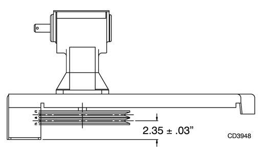
Figure 25. Drive Pulley Installation