8 minute read
OWNER SERVICE


A WARNING
Before servicing, adjusting, repairing or unplug-
ging, stop tractor engine, place all controls in neutral, set park brake, remove ignition key, and wait for all moving parts to stop.
Keep all persons away from operator control
area while performing adjustments, service, or maintenance.
A CAUTION
Your dealer can supply original equipment
hydraulic accessories and repair parts. Substitute parts may not meet original equipment specifications and may be dangerous.
Always wear relatively tight and belted clothing
to avoid getting caught in moving parts. Wear sturdy, rough-soled work shoes and protective equipment for eyes, hair, hands, hearing, and head; and respirator or filter mask where appropriate.
The information in this section is written for operators who possess basic mechanical skills. Should you need help, your dealer has trained service technicians available. For your protection, read and follow all safety information in this manual.
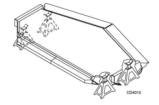
BLOCKING METHODS
Jack stands, with a load rating of 1,000 pounds or more, are the only approved blocking device for this mower. A minimum of four jack stands, located under the mower as shown in Figure 8, must be installed before working underneath this unit. Do not position jack stands under wheels, axles, or wheel supports because these components can rotate. Do not work underneath unless it is properly attached to tractor (see Operation Section), the brakes set, key removed, and the mower blocked securely. The mounted unit will be anchored to minimize side to side and front to rear movement. The pull-type unit will be anchored front to rear. For the mounted unit, tighten tractor lower 3-point arm anti-sway mechanisms to prevent side to side movement. For the pull-type unit, raise mower with the standard ratchet adjustment link or the optional hydraulic cylinder. When the optional hydraulic cylinder is installed the standard equipment transport bar must be pinned in the raised position. With either the ratchet adjustment link or the optional hydraulic cylinder, lower mower to transfer its weight to the jack stands, but do not raise the rear wheels off of the ground. When blocking, you must consider overall stability of the unit. Just placing jack stands under the unit will not ensure your safety. The working surface must be level and solid to support the weight on the jack stands. Ensure jack stands are stable both top and bottom, and mower is approximately level. With full mower weight lowered on jack stands, test blocking stability before working underneath mower.
Figure 8. Jack Stand Placement (Tractor and Connection Not Shown)
LUBRICATION INFORMATION (FIGURE 9)
Figure 9 shows the lubrication points. The accompanying chart gives the frequency of lubrication in operating hours, based on normal conditions. Severe or unusual conditions may require more frequent lubrication. Do not let excess grease collect on or around parts, particularly when operating in sandy areas. Use SAE 90W gear lube in gearbox. Check gearbox daily for evidence of leakage at both seals and the gasket between the housing and cover. If leakage is noted, repair immediately. There may be a small amount of lube emitted from the vent plug; this is not considered leakage. Check the gearbox every day using the dipstick. Oil level is to be up to the ring but not over. Overfilling the gearbox will cause the excess gear lube to blow out vent plug. The gear lube could then ruin the belt. Use a lithium grease of No. 2 consistency with a MOLY (molybdenum disulfide) additive for all locations. Be sure to clean fittings thoroughly before attaching grease gun. When applied according to the lubrication chart, one good pump of most guns is sufficient. Do not overgrease. Daily lubrication of the driveline slip joint is necessary. Failure to maintain proper lubrication can result in
damage to U-joints, gearbox, tractor PTO and/or the mower driveline. Disconnect driveline from the tractor. To lubricate driveline slip joint, insert a grease gun through shield slots (keep fingers out of slots to prevent injury) and apply grease to grease fitting. Move driveline in and out to distribute grease over the entire working area. Connect driveline to tractor. Driveline shield bearings (12) must be greased every eight hours. This operation requires a needle point adapter for a grease gun. Insert the needle point into the bearing hole and apply one good pump.
Ref No. Description Frequency
1 Front U-Joint 8 Hours 2 Rear U-Joint 8 Hours 3 Gearbox, Cover half of horizontal shaft with SAE 90W gear lube Check Daily 4 Tailwheel Pivot Arm 8 Hours, Repack 5 Tailwheel (Mounted Model) 250 Hours 6 Slip Joint Zerk (Mounted Model) 8 Hours 7 Tailwheels (Towed Model) 10 Hours 8 Driveline Carrier Bearing (Towed
Model) 10 Hours
9 Slip Joint Zerk (Towed Model) 10 Hours 10 Center U-Joint (Towed Model) 10 Hours 11 Ratchet Adjustment Link 100 Hours 12 Shield Bearing 8 Hours 13 Left Blade Spindle 10 Hours 14 Center Blade Spindle 10 Hours 15 Right Blade Spindle 10 Hours
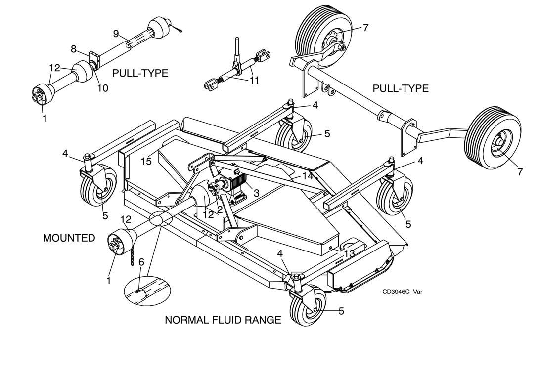
Ref No. Description Frequency
Figure 9. Lubrication Points
Figure 10. Belt Installation

BELT REPLACEMENT (FIGURE 10)
One of the major causes of belt failure is improper installation. Before a new belt is installed, check pulley shafts and bearings for wear. Check pulley grooves for cleanliness. Make sure spindles turn freely and without wobble. If grooves require cleaning, use a cloth moistened with a non-flammable, non-toxic degreasing agent or commercial detergent and water. Avoid excessive force during installation. Do not use tools to pry belt into pulley groove. Do not roll belt over pulleys to install. This can cause hidden damage and premature belt failure.
NOTICE
■ Use care when installing or removing belt from
spring-loaded idler in step 6. Springs store energy when extended and, if released suddenly, can cause personal injury.
Belt replacement is accomplished in these steps: 1. Loosen nut and swing belt guide (G) away from pulley (F). 2. Loosen nut on eyebolt (H) to relax tension in spring. 3. Slide belt under and around drive pulley (A). 4. Route belt around pulley (F), idler (E) and pulley (D) as shown. 5. Make sure belt is on drive pulley (A) and route belt around spring-loaded idler (C). 6. Grasp belt between spindle pulley (B), springloaded idler (C) and spindle pulley (D). Pull springloaded idler with belt and route belt over pulley (B). 7. Tighten nut on eyebolt (H). Make sure springloaded idler arm pivots freely with belt installed. 8. Set belt guide (G) 1/8" away from belt. Tighten to 85 lbs-ft.
SHEAR BOLT REPLACEMENT NOTICE
■ Always use approved 1/2" NC x 3" grade 2
shear bolt as a replacement part. Using a hardened bolt or shear pin may result in damage to driveline or gearbox.
Rotate driveline to align holes in yoke and shaft. Install shear bolt and secure with lock nut.
CHAIN OR RUBBER SHIELDING REPAIR
A DANGER
Full chain or rubber shielding must be installed
when operating in populated areas or other areas where thrown objects could injure people or damage property. • If this machine is not equipped with full chain or rubber shielding, operation must be stopped when anyone comes within 300 feet (92 m). • This shielding is designed to reduce the risk of thrown objects. The mower deck and protective devices cannot prevent all objects from escaping the blade enclosure in every mowing condition. It is possible for objects to ricochet and escape, traveling as much as 300 feet (92 m).
Inspect chain shielding each day of operation and replace any broken or missing chains as required.
SIDE SKID REPAIR
Side skids are replaceable. Check them periodically and replace as necessary.
1. Side skid bar 2. 3/8 x 1-1/4" Clipped head bolt 3. 3/8 " Lock washer 4. 3/8" Hex lock nut
Figure 11. Side Skid Repair

BLADE SERVICING
A CAUTION
Your dealer can supply genuine replacement
blades. Substitute blades may not meet original equipment specifications and may be dangerous.
Make certain all movement of equipment com-
ponents has stopped before approaching for service.
Low suction and general purpose suction blades are available. Use low suction blades in sandy areas where abrasive action could cause excessive blade wear. General purpose suction blades are recommended for all other applications. Inspect blades before operation for condition and ensure they are securely fastened. Replace blades that are bent, excessively nicked, worn or have any other damage. Small nicks may be ground out when sharpening. Replace blades on a spindle in pairs; an old blade and a new blade may vary excessively in weight and cause vibration. Never mix blade types.
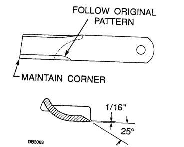
Blade Sharpening
Follow the original sharpening pattern. Make an effort to maintain balance on both blades from a spindle by grinding the same amount from them. Blades that vary excessively in weight can cause vibration. Figure 12. Blade Sharpening
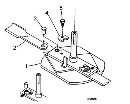
Blade Removal
This mower is equipped with quick change blades. Open blade access cover, loosen bolt (5) and rotate blade lock (4) to allow for removal of blade pin (3). Remove blade (2). Rotate spindle and remove opposite blade in same manner.
Blade Installation
Make sure to position blade so the cutting edge leads in a counter-clockwise rotation. Install blade (2), then place blade pin (3) in hole and rotate blade lock (4) to secure blade. Tighten bolt (5). Rotate spindle and install opposite blade in same manner. Repeat for remaining spindles.
1. Blade spindle 2. Blade 3. Blade pin 4. Blade lock 5. 1/2 x 3/4" Nylock bolt
Figure 13. Blade Installation and Lock
WHEEL BEARING MAINTENANCE RM990-3 ONLY
At least once each mowing season or 250 hours of operation, whichever occurs first, the bearings in the tailwheel should be removed, cleaned and repacked. Replace bearings and cones if broken or worn excessively. Install the wheel in the wheel yoke and tighten the inner nut until there is a slight bearing drag (similar to automobile wheels). Hold the inner nut and tighten the lock nut against it to maintain bearing adjustment.