11 minute read
Instruments and Controls


This chapter describes the instruments, panels and controls Volvo Penta sells for your engine. If you would like to complement your instrumentation, or if your boat is equipped with instruments not described here, we ask that you contact your Volvo Penta dealer.
Ignition Lock
The start keys are supplied with a plate bearing the start code to be used when ordering spare keys. Keep the code beyond the reach of unauthorized people. S = Stop position. 0 = The key can be inserted or removed. I = Operating position. System voltage is connected. II = Not used. III = Start position. Start motor is engaged. Read the starting instructions in chapter Starting page 28 to ensure you use the correct start procedure.
Start/Stop Panel
The start/stop panel is used for starting and stopping the engine. To start the engine it is necessary for the start key at the main station to be in the ”I” operating position. The engine can only be stopped from an activated control panel. Read the starting instructions in chapter Starting page 28 to ensure you use the correct start procedure.
1
P0005255
Gauges
Tachometer
The tachometer displays engine speed; multiply the value shown on the dial by 1,000 to get the number of engine revolutions per minute. Boat and engine information is displayed in the tachometer window. Information displayed depends on engine type, the number of sensors and which accessories are installed.
Optional instruments
These instruments are sold as engine options by Volvo Penta.
1 Fuel level gauge
The fuel level gauge shows the quantity of remaining fuel. 2 Voltmeter, battery charging
The meter shows the alternator charge current.
During operations the charge voltage should be around 14 V. When the engine is stopped and electrical power switched on the battery voltage should be around 12 V.
If a 24 V system is installed, the charge voltage should be around 28 V during operations. 3 Coolant temperature gauge
The instrument shows engine coolant temperature.
During operations coolant temperature should normally be between 75-90°C (167-194°F). 4 Oil pressure gauge
The oil pressure gauge displays engine oil pressure. During operations the oil pressure gauge should normally show 4-5.5 bar. At idle, lower values are normal. 5 Rudder position indicator
The instrument shows rudder position. 6 Fresh water level sensor
Freshwater tank level gauge. 7 Alarm monitor
The alarm monitor gives a visual warning to call attention to any alarms that occur.
Control panel single installation
Control panel twin installation
Control Panel
The control panel is used for station handling, disengaging the gear/drive and to navigate the EVC system menu. There is one control panel for single installations and one for twin installations. Always push the buttons firmly and for at least one second.
Activation button
The control panel and station are activated by pushing the activation button once. Push twice to lock the station. On boats with only one station, this is always active. The lamp above the activation button shows the status of the station. Red lamp: Active station Lamp off: Station not activated. Lamp flashing: A fault that limits the function of the station has been detected.
Padlock
The padlock symbol lights when the station is locked with the activation button or if change of stations is under way, please refer to section Helm Stations page 34. Lit: The station is locked and the boat can only be controlled from this station. Flashing: Another station is locked.
Neutral button
The neutral button is used to disengage the drive/gear enabling the engine rpm to increase without affecting the drive/gear, to warm up the engine. The lamp above the neutral button shows the status of the station. Green lamp: Gear in neutral. The drive/gear is in neutral position and the engine runs at idle speed. Lamp off: The drive/gear is engaged for movement forward/astern. Flashing lamp: The drive/gear is disengaged and the engine speed can be adjusted.
Knob
Navigate the display menu by turning the knob. Push the knob to confirm a selection or acknowledge an alarm.
Tachometer Display Selection
Boats with twin installations with one tachometer for port engine and one for starboard can choose which engine menu to handle from the station. The lamp
above the button shows which engine is chosen, green lamp for starboard engine and red lamp for port engine. Lamp off: Menu inactivated. Lamp lit: Menu activated.
Multifunction Button
With the multifunction button the instruments and panels backlighting is adjusted. Push the button for over a second to turn the backlighting on or off. The backlighting can be adjusted in five stages by repeatedly pushing the multifunction button quickly (less than 1 second). If the button is pressed on an inactive station, operating information is shown on the display(s) and the menu structure is activated.
Back Button
Used to return a step up in the menu structure.
EVC System Display
In the EVC system display it is possible to show multiple windows with different information. There are four display modes which can be chosen using the buttons on the instrument. Button 1–4 shows the different display modes. Button 5 i used to adjust the contrast and to access the configuration menu, please refer to section Configuration menu. The EVC menu can be shown in the display by entering System information, refer to section Multi, button 2, or the Configuration menu. In this mode the display works the same way as the display in the tachometer and is handled via the separate control panel, please refer to section Instruments and Controls page 19. If no tachometer is installed the EVC meny can be reached by pressing the knob on the control panel. To get back to the display modes, press . At start up, the display performs a self-test. If an constant signal is heard, the system has discovered a malfunction. The display will work but may act in an unexpected way. NOTICE! Only installed functions will be shown in the display.
Press button 1–4 to view the function menu for the buttons, apperaring in the lower part of the display. Press button 1–4 to choose the desired display mode. 1 Engine 2 Multi 3 Trip 4 Graph To leave the menu, wait a few seconds or press button 5 (EXIT).
Contrast
In the display modes Engine, Trip and Graph, it is possible to adjust the contrast. Press button 5 when outside the menu and then + (button 4) and – (button 3).
Engine, button 1
Rpm and speed is shown in the upper part of the display. In the lower part it will show trip computer and a fuel level indicator, if these functions are installed. If speed information is missing, coolant temperature will be shown instead. Navigate in the trip computer by repeatedly press button 1. • Fuel Rate, fuel consumption per hours
Fuel Economy, fuel consumption per distance • Trip Fuel, fuel used since last reset • Fuel Remaining, remaining fuel in tank • Dist. to Empty, remaining distance until tank is empty, based on fuel consumption per distance • Trip Distance, trip distance since last reset


In the multi mode the information can be shown in several windows, analogue or digital. The display can show windows with different information or be divided to show windows and system information. To handle the system information, see section Instruments and Controls page 19. To go between the different display modes, press button 2 repeatedly.
By pressing button 5 (the right arrow) you can choose which information to be shown in the different windows. Press repeatedly on the button which correspond to the window, until desired information is shown.
Trip, button 3
The display works as trip computer and shows:
Trip Fuel, since last reset
Fuel Rate, fuel consumption
Trip hours, since last reset
Engine hours, total amount of operating hours Reset by pressing button 3 for three seconds until a beep is heard. For twin installations the values are summarized, except for engine hours that are shown for each engine.
Graph, button 4
The information is shown as graphs. Press button 4 repeatedly to choose which information will be shown. The time interval is set in the Configuration menu. If the connection is broken there will be a straight line in the display.
Single installation
Twin installation In a twin installation the port engine is shown as a black line and the starboard engine as a grey line.
Configuration menu
Press button 5 for five seconds to enter the Configuration menu. Navigate with the up and down arrows, select with the right arrow. NOTICE! The port engine, or both engines, must have the ignition on when display settings are made.
System information
System information shows the EVC-menyn and is handled by the knob on the control panel. For more information, see Instruments and Controls page 19.
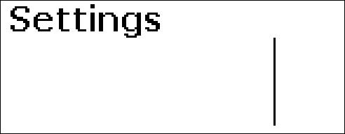
Settings
- Language: Setting of what language the information is to be presented in are made in the EVC menu, see Instruments and Controls page 19. - Bleep: On/Off, setting if pressing the instrument buttons will be followed by a beep or not. - Engine: Setting of what kind of installation the display is a part of and which engine is to be shown in the display.
- Display: Setting of intervals (unit settings are made in the EVC menu, see Instruments and Controls page 19):
Rpm interval, 2500–9000 rpm, in steps of 500 rpm
Speed, on/off
Speed interval, 10–100 knots, in steps of 10 knots
Graph interval, 2 min, 10 min, 30 min, 60 min, 2 h, 4 h or 8 h
EVC menu
A B

P0001006 The EVC menu can be shown in both the EVC system display and the tachometer display. The main menu shows operating information, the settings menu and the fault menu (only shown when a fault in the system is detected). Only installed functions are shown in the menu. Turn the knob to navigate through the menus. Press the knob to access sub menus and to confirm selections in the settings menu. It is always possible to return to the previous menu by pressing . Press repeatedly to return to the main menu; alternatively, hold down the button for a couple of seconds.
A This field displays engine operating data. B This field displays warning symbols and active function symbols.
P0001015

P0001315 Turn the control panel wheel until the start screen for the settings menu is displayed. Press the wheel to reach the sub menus. Turn to move between the available setting functions. For further information, refer to section Settnings menu page 88.
Fault
The fault window is only shown in the main menu if a fault has been detected. For further information, refer to section Fault Handling page 39.

Controls
This section describes the controls Volvo Penta sells for your engine. Contact your dealer if your boat is equipped with controls other than those described here, and you feel uncertain about their function.
Single Lever Control
Maneuvering
A single-lever control operates both gearshift and throttle functions with the same lever. The engine can only be started with the control lever in the neutral position. N = Neutral position. Reverse gear/drive disengaged and engine at idle. F = Reverse gear/drive engaged for forward motion. R = Reverse gear/drive engaged for rearward motion. T = Engine rpm control (throttle).
Disconnecting the gearshift function
The gearshift function can be disconnected so that the control lever only operates the throttle. 1 Put the control lever in neutral (N). 2 Depress the neutral button (N) and keep it depressed at the same time as the lever is moved forwards to the gearshift position (F). 3 Release the neutral button. The green indicator will flash as confirmation that the gearshift function is disconnected and the that lever will only affect engine revolutions. The gear shift function is reconnected automatically when the lever is returned to the neutral position. This is confirmed by the green indicator shining continuously.
CAUTION!
Take care not to engage the drive by mistake.


Control A The control lever is fitted with a friction brake that can be adjusted to apply more or less resistance to lever movement. The friction brake only affects movement of the throttle control lever. 1 Stop the engine. 2 Move the control lever forward so that the groove in the lever hub is accessible. 3 Remove the plug with the aid of a screwdriver. 4 Adjust the friction brake (wrench, 8 mm) by turning the bolt clockwise (+) for stiffer lever movement, and counterclockwise (-) for easier movement. 5 Reinstall the plug.
Dual lever control
Maneuvering
A twin-lever control has separate levers for the gearshift function (1) and rpm control (throttle) (2). The engine can only be started with the control lever in the neutral position.
Black lever (1)
N = Neutral position. Reverse gear/drive disengaged and engine at idle. F = Reverse gear/drive engaged for forward motion. R = Reverse gear/drive engaged for rearward motion.
Red lever (2)
Engine rpm control (throttle).
Control B

The control lever is fitted with a friction brake that can be adjusted to apply more or less resistance to lever movement. Adjust the friction brake by turning the screw (control A), or by twisting the lever (control B). Turn clockwise (+) for stiffer lever movement, and counterclockwise (-) for easier movement.