4 minute read
Lower gear

from Volvo Penta 280, 280-DP, 285, 290, 290-DP SP-A, SP-C, DP-A, DP-B, DP-C Drives Workshop Manual - PDF

Reconditioning the lower gear, models 280, 285, 290 and SP
Disassembly
The propeller shaft
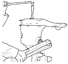
NOTE! In order not to damage the oil deflector during the dismantling, apply the bending tool close to the 2 carrier pins (3). (This is valid for sterndrives of earlier manufacture). On sterndrives of later manufacture the carrier pins have been replaced by a load pin.
13. Lift out the pinion (1) and the needle bearing washer (2).
NOTE! The needle bearing is a full needle type of bearing with loose needles (3). Remove all 27 needles.
884381 884143
15. Press (knock) off the outer ring of the needle bearing. Use special tools 884381 and 884143. Insert the tool from underneath and the shaft from above.
14. Carefully lift off the lower gear housing from the vertical drive shaft.
NOTE! Take care of the shims (1).
16. Press off the ball and roller bearings from the vertical shaft (against the frame of the press).
NOTE! There are spacer pads between the bearings.
884316
Assembly
Oil all moving parts and the screws prior to assembly.
17. Should the needle bearing of the propeller shaft be damaged, use special tool 884316 to remove it. Insert the puller into the needle bearing in a way that the barbs of the puller end up at the backside of the needles. Then tighten the puller forcing the barbs apart and pull out the bearing.
1. Fill up with grease between the two sealing rings (1) and press them home in the propeller bearing housing. Use special tools 884283 and 9991801
NOTE! Turn the sealing rings correctly. They are to seal against the oil in the gear housing as well as against water.
9991801
884283
18. Remove the bearing race on the propeller shaft by cracking it. Clean all parts and check them for wear. Replace parts if necessary.
NOTE! The gear wheels are sold in matched pairs in order to obtain the correct contact pattern.
2. Install the needle bearings for the propeller shaft. The side of the needle bearing carrying the description must be turned facing aft. Use special tools 884283 and 9991801.
NOTE!
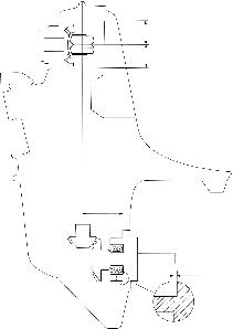
8. Install the vertical shaft with a 0.35 mm (0.14") thick shims package (1) consisting of a paper shim 0.25 mm (0.01") between two metal shims 0.05 mm (0.002") each.
884830
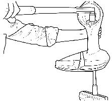
9. Install the washer and the nut. Tighten the nut with a torque of 160 Nm (118 lbf.ft.). Use special tool 884830 on the splined end as a counter hold.
NOTE! Don’t lock just yet.
884140
884143
The propeller shaft
12.
) deflector coincide with the carrier pins (on sterndrives of earlier manufacture). On sterndrives of later manufacture a load pin acts as carrier of the oil deflector.
NOTE! Make sure that the two holes on the
Shimming Method 1
1. The lower gear housing is stamped with a ‘F’-measurement (center vertical shaft – contact surface of the propeller bearing box), the propeller bearing box is stamped with a ‘G’-measurement (shoulder of the propeller bearing – contact surface of the propeller bearing box). Add these measurements together.
2. The gear length is fixed at 5.85 mm (0.230"). Add or subtract the plus or minus marking of the gear wheel. Subtract from this sum the sum of the ‘F’ and ‘G’ measurements. The sum thus obtained denotes the thickness of the shim.
NOTE! On some gear housings for instance the figures 03 can be stamped or some other figure. In these cases add the number 5.00 to that of the ‘F’-measurement and the figure 1.00 to that of the ‘G’-measurement. Then the ‘F’-measurement ends up being for instance 5.03 or some other measurement above 5 mm and the ‘G’-measurement for instance 1.03 or some other measurement above 1.0 mm*
If the sum obtained does not coincide with available shims, select the closest five – or ten – number. How to calculate the shim thickness can be seen in the following example:
Measurement ‘F’*
4.97(0.195")stamped
Measurement ‘G’* +0.98(0.039")stamped
5.95(0.234")5.95
Gear wheel5.85(0.230")fixed
Gear wheel marking+0.04(0.002")etched**
5.89....5.89
Calculated sum always positive!0.06 (0.002")
As per this example a 0.05 mm (0.002") shim is inserted between the propeller bearing box and the propeller thrust bearing. Carry on according to points 4–12 below!
*These measurements are examples.
**Only the figure 4 is etched on the gear wheel
Method 2
3. Insert the 0.2 mm (0.008") shim (1) in the propeller bearing housing. This is a value of experience.
4. Install the propeller shaft along with bearings in the gear housing. Be careful so that the bearing does not end up obliquely in the bearing housing or that the sealing rings are damaged. Make sure that the six holes in the washer coincide with the screws. Insert the nuts before the bearing is pushed home completely in the bearing box. Tighten the six nuts.
5. Install the propeller shaft with its bearing box in the gear housing. Tighten the screws with a torque of 40 Nm (29.5 lb.ft.)
NOTE! The two O-rings (1) on the bearing housing should not be installed.
7. If the backlash is found not to be correct, adjust as follows:
If the method 1 has been used: If the backlash is too small, increase the shim thickness underneath the ball bearing (1) and if the backlash is too big, decrease the shim thickness.
If method 2 has been used: If the backlash is too small decrease the shim thickness in the propeller bearing housing (2) and if the backlash is too big, increase the shim thickness.
6. Check the gear backlash and measure it directly against the vertical splines shaft. The clearance should be 0.06–0.10 mm (0.002–0.004") resulting in a gear backlash of 0.15–0.25 mm (0.006–0.020")
8. Remove the screws and pull out the propeller shaft. Coat the gear teeth of the gear wheel and the pinion with marking dye. Then install the propeller shaft with the bearing box in the gear housing. Tighten the screws with a torque of 40 Nm (29.5 lb.ft.).
9. Install special tool 884830 onto the splines end and turn the gear in the set direction of rotation, clockwise for left handed propeller. At the same time brake the movement on the propeller shaft, as forcefully as possible.
11. Should the contact pattern correspond to that of picture “B”, reduce the shim thickness for the vertical shaft and the propeller shaft.
Contact pattern
10. Check that the contact pattern on the teeth surfaces of the drive side coincide with that of the picture “A”, which is correct. The contact pattern should be positioned in the middle of the tooth but displaced towards the small end.
12. Should the contact pattern correspond to that of picture “C”, increase the shim thickness for the vertical shaft and the propeller shaft.
NOTE! If the pinion is moved the gear wheel must be moved correspondingly in order not to alter the gear backlash.