
4 minute read
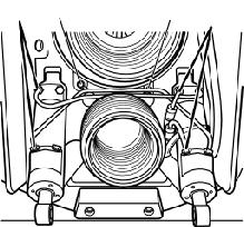
Transom shield

from Volvo Penta 280, 280-DP, 285, 290, 290-DP SP-A, SP-C, DP-A, DP-B, DP-C Drives Workshop Manual - PDF

Changing trim cylinders, models 290, SP and DP
1. Remove the sterndrive when the boat is on land. Also remove the exhaust bellows and the universal joint bellows. Remove if necessary barnacles etc and clean the shield.
Trim cylinders, earlier models
Trim cylinders, later models
4. Remove the 2 hoses (A) from the starboard cylinder. If only the port cylinder is to be replaced, remove the pipe connections on that cylinder (B).
WARNING! Be sure to catch any oil which will leak when the hydraulic lines are disconnected.
2. Remove the 2 hoses and the pipes from the starboard cylinder. If only the port trim cylinder is to be replaced, remove the pipe connections. Watch out for oil running out.
WARNING! Be sure to catch any oil which will leak when the hydraulic lines are disconnected.
3. Remove the plastic plug with a 5 mm Allen-head key.
5a. Port Cylinder:
If the port cylinder is to be removed, remove the ground strap terminal (C, figure above) and insert from the transom shield.
5b. Starboard Cylinder: Remove the plastic plug (D, figure above) adjacent to the trim cylinder attachment pin.
Trim cylinders, all models
Part no. 940194
6.
Use grease nipple, Volvo Penta part no. 940194.
8. Use a grease gun and inject grease into the grease nipple. The dowel pin will then be pushed out and the trim cylinder can be removed.
884978
9. If the dowel pin will not come out by using a grease gun, special tool 884978 should be used as follows: Remove the grease fitting.
Fill the tool with grease.
Screw the tool into the transom shield and carefully tighten.
Unscrew the locking trim cylinder pin locking bolt (1) approx. 10 mm (¼”).
Hit the tool piston (2) with a hammer so that the trim cylinder pin is forced against the locking bolt.
IMPORTANT! The transom must have cutouts called for on the transom template to allow sufficient clearance for the pins to be removed. If the cutouts are not made, the transom shield must be removed from the boat to enable trim cylinder pin removal.
11. Always use a new O-ring (1) on the dowel pin during reassembly. Check the pin hole and pin for scratches or other damage. Position (2) is the locking bolt.
12. Remove the grease fitting that was used to remove the attachment pin. Grease and install the trim cylinder dowel pin. Install the new trim cylinder. Remove the attachment bolt from the end of the pin and lock the pin in position with the bolt.
NOTE!
Trim cylinders, earlier models
Trim cylinders, later models
13. Remove any shipping plugs installed in the new trim cylinder.
Install the pipes and the hoses on the new trim cylinder.
WARNING! Make sure all the pipes and hose fittings are attached finger tight before torquing any of the fittings. Final tightening of any of the fittings before all fittings are started could cause cross-threaded fittings and damage the cylinder.
Install the sterndrive according to chapter Installing the Sterndrive
Raise and lower the sterndrive several times to bleed any air trapped in the hydraulic system.
14. Remove any shipping plugs installed in the new trim cylinder.
Install the pipes and the hoses on the new trim cylinder. Hoses to starboard cylinder (A) and port cylinder (B).
WARNING! Make sure all the pipes and hose fittings are attached finger tight before torquing any of the fittings. Final tightening of any of the fittings before all fittings are started could cause cross-threaded fittings and damage the cylinder.
15a. Port cylinder:
Remove the block off plugs from the old cylinder and install in the same holes of the new cylinder. Install the ground strap insert (C), attach the ground strap to the insert.
WARNING! Be sure there is good electrical contact (low resistance) between the trim cylinders and the transom shield. High resistance between the transom shield and the trim cylinders will result in corroded trim cylinders. For more information on electrochemical corrosion, consult publication 7733534-7 Marine Electrical Systems available from Volvo Penta parts.
15b. Starboard cylinder:
Install the plastic plug (D).
Install the sterndrive according to chapter Installing the Sterndrive
Raise and lower the sterndrive several times to bleed any air trapped in the hydraulic system.
Trim cylinders, all models
Trim pump, earlier model
IMPORTANT! The hydraulic pump must be installed vertically, as reflected by the picture.
16. Remove the oil filler/indicator plug to check the oil level. Top up if necessary. Install the sterndrive in the transom shield. Raise and lower the drive simultaneously to facilitate the topping up and to make sure that the system is properly filled up. The oil level should be level with the oil filler hole. Use the same oil quality as for the engine or ATF oil. See below.
Trim pump, later model
17. Oil level, hydraulic pump – power trim: Trim in the drive as far as possible. Check that the oil level is between the max and min. marks on the reservoir. Top up if necessary with ATF oil.
NOTE! Early production drives were filled with engine oil and have that recommendation in the Owner’s Manual. Late production drives have ATF oil filled.
IMPORTANT! We recommend the use of ATF oil. Observe strict cleanliness so that dirt is not drawn in by the oil.
ATF oil and engine oil must never be mixed. If ATF oil is to be used, the engine oil must first be drained from the system. If the system has been drained, fill up with new oil and trim the drive 6 to 10 times in and out to purge air from the system. Check the oil level and top up if necessary.
Trim pump, earlier model
Trim pump, later model
18. Should the low pressure hoses (1) and high pressure hoses (2) need to be disconnected for any reason it is vital that they be reconnected to the correct hose connection.
The figures above show how the hoses shall be connected on the inside and outside of the transom shield.
NOTE! The outer low pressure hose (3) is marked white and the outer high pressure hose (4) is marked red.
