11 minute read
Chapter 3 Machine Disassembly and Replacement


Machine Disassembly and Replacement
This chapter contains step-by-step procedures on how to disassemble the notebook computer for maintenance and troubleshooting. To disassemble the computer, you need the following tools: Wrist grounding strap and conductive mat for preventing electrostatic discharge Small Philips screw driver Philips screwdriver Plastic flat head screw driver Tweezers NOTE: The screws for the different components vary in size. During the disassembly process, group the screws with the corresponding components to avoid mismatch when putting back the components. When you remove the stripe cover, please be careful not to scrape the cover.
Before You Begin
Before proceeding with the disassembly procedure, make sure that you do the following: 1. Turn off the power to the system and all peripherals. 2. Unplug the AC adapter and all power and signal cables from the system. 3. Remove the battery pack.
The flowchart on the succeeding page gives you a graphic representation on the entire disassembly sequence and instructs you on the components that need to be removed during servicing. For example, if you want to remove the system board, you must first remove the keyboard, then disassemble the inside assembly frame in that order.
Start
Battery
Middle Cover
Lower Case Assembly
O*2 H*2
DIMM Cover Memory
P*1
Keyboard E*1 ODD Module
J*2 on bottom side K*2 on top side
LCD Module
E*1 on upper case assemby E*12 on bottom side F*3 on bottom side A*2 on rear side
RTC Battery
Bluetooth Module
Lower Case Main Board Assembly
*2
Speaker Set 86.9A353.3R0*2 C*1 D*2
North Bridge Plate CPU Heatsink Upper Case
86.9A353.3R0*2
Modem Board O*2
Fan H*3
HDD Cover Wireless LAN Card
O*4
HDD Module
M*4
HDD Bracket HDD
Upper Case Assembly Microphone
Touchpad Bracket Touchpad Assembly
N*3
Touchpad
CPU ODD Module
G*2
ODD ODD Bracket
LCD Module
4 screw caps
J*4 for 15" J*8 for 15.4"
LCD Bezel
LCD Panel I*2
LCD Assembly
G*8 I*2
LCD Inverter
LCD LCD Wire Cable LCD Brackets
Screw List
Item Description
Part Number
A SCW HEX NYL I#R-40/O#4-40 L5.5 34.00015.081 B SCREW MACH WAFER M2*L4 NI 86.00059.220 (PC Card slot x4) C CPU SCREW M2.5*4.3L (2.3 KG) 86.00D01.230 D CPU SCREW M2.5*4.3L (1.55 KG) 86.00D02.230 E SCREW M2.5-6 86.9A323.6R0 F SCRW M2.5*L8(NON NYLOK) 86.9A323.8R0 G SCREW M2*3 NYLON 1JMCPC-420325 86.9A352.3R0 H SCREW 86.9A352.4R0 I SCREW M2.5*4L(NYLOCK)BLACK ZN 86.9A353.4R0 J SCREW M2.5X6 86.9A353.6R0 K SRW M2.5*8L B/ZN NYLOK 700 86.9A353.8R0 L SCRW M2.5*L3(NON NYLOK) 86.9A523.3R0 M SCREW M3x4(86.9A524.4R0) 86.9A524.4R0 N SCREW WAFER NYLOK NI 2ML3 86.9A552.3R0 O SCRW M2*4 WAFER NI 86.9A552.4R0 P SCRW M2.5*3 WAFER NI 86.9A553.3R0
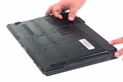
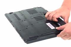
1. Unlock the battery lock. 2. Slide the battery latch then remove the battery.
Removing the Wireless LAN Card/the HDD Module/the Memory/the ODD Module and the LCD Module
Removing the Memory and the HDD Module
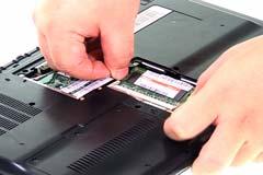
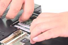
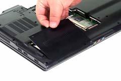
1. Remove the five screws fastening the DIMM cover. 2. Detach the DIMM cover carefully.
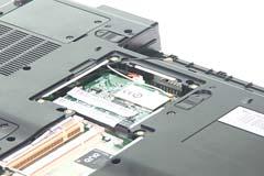
3. Pop out the memory carefully. 4. Disconnect wireless main and auxiliary antenna from the wireless LAN card. 5. Pop out the wireless LAN card and remove it.
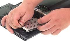
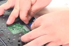
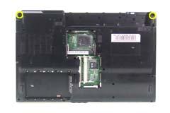
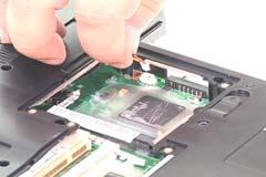
6. Remove the three screwss fastening the HDD cover. 7. Detach the HDD cover from the main unit.
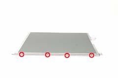
8. Remove the four screws fastening the HDD module. 9. Then detach the HDD module carefully.

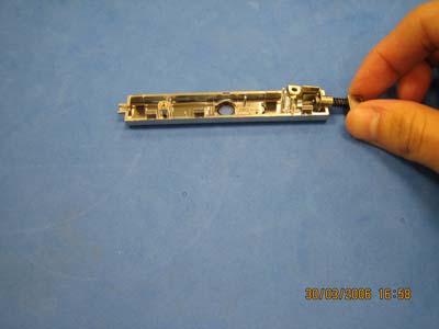
Removing the ODD Module
1. First, remove the screw fastening the ODD module as shown. 2. Push the ODD module outwards then remove it.

Removing the LCD Module
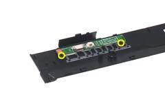
1. Detach the middle cover from the main uiit carefully. 2. Disconnect the launch board FFC from the launch board.
3. Remove the middle cover (with launch board and microphone) from the main unit. 4. Disconnect the microphone cable from the launch board.
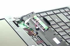
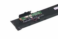
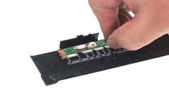
5. Take out the microphone from the middle cover. 6. Remove the two screws fastening the launch board. 7. Then remove the launch board from the middle cover.
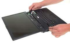
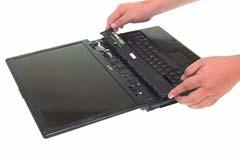
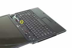
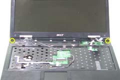
8. Remove the screw holding the keyboard. 9. Turn over the keyboard as shown. 10. Disconnect the keyboard cable.
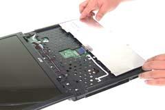
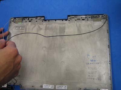
11. Remove the keyboard from the main unit. 12. Tear off the tapes fastening the wireless antenna cable.

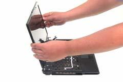
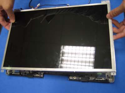
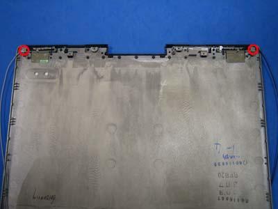
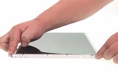
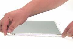
13. Pull the antenna set from the main unit. 14. Disconnect the LCD cable. 15. Turn over the notebook then remove two screws fastening the LCD module.
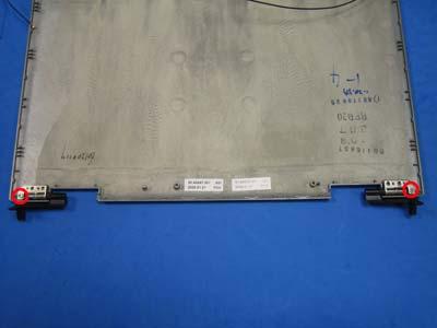
16. Remove two screws fastening the LCD hinges. 17. Then detach the LCD module from the main unit.
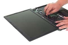
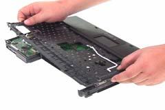
Separate the Main Unit Into the Upper and the Lower Case Assembly
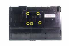
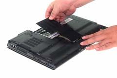
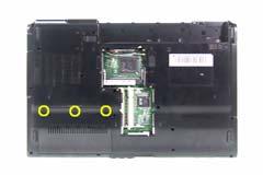
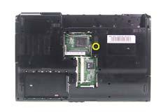
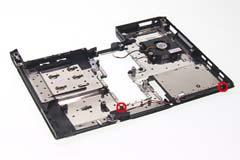
1. Disconnect the touchpad cable and the LED FFC from the main board. 2. Remove the 15 screws on the bottom as shown. 3. Detach the upper case assembly from the lower case assembly carefully.

Disassembling the Lower Case Assembly
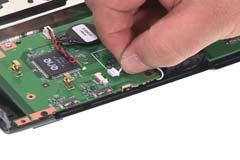
4. Turn over the lower case assembly to the bottom side, then disconnect the fan cable. 5. Turn over the lower case assemlby to the fron side, then detach the bluetooth module.
6. Disconnect the Bluetooth cable from the main board. 7. Disconnect the Bluetooth cable from the Bluetooth module as shown.
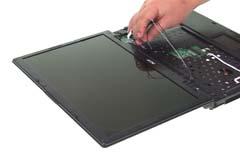
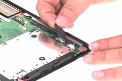
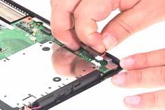
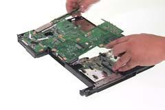
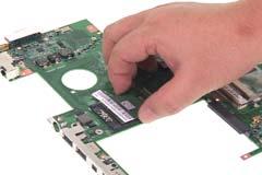
8. Disconnect the speaker set cable from the main board. 9. Remove the four screws fastening the main board to the lower case. 10. Detach the main board from the lower case carefully.

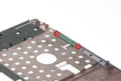
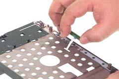
11. Remove the two screws holding the speaker set. 12. Take out the speaker set from the lower case.
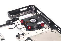
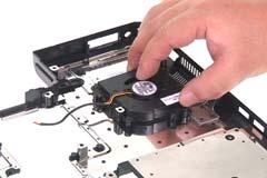
13. Remove the three screws fastening the system fan. 14. Detach the fan from the lower case.
15. Disconnect the RTC battery cable then detach the RTC battery. 16. Disconnect the launch board FFC from the main board.
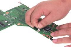
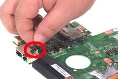
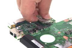
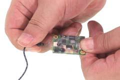
17. Disconnect the modem cable from the main board. 18. Disconnect the modem board from the main board. 19. Disconnect the modem cable from the modem board as shown.
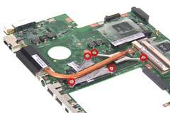
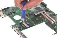
20. Remove the five screws fastening the heatsink. 21. Remove the heatsink from the main board.

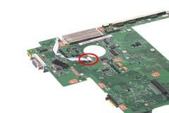
22. Use a flat-headed screwdriver to release the CPU socket lock. 23. Remove the CPU from the CPU socket carefully.
Disassembling the Upper Case Assembly
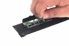
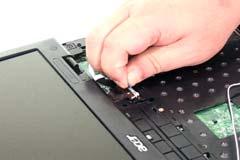
1. Remove the two screws fastening the LED board. 2. The remove the LED board from the upper case assembly carefully.
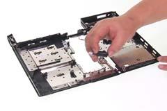
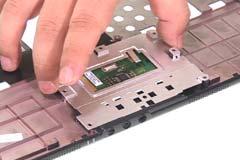
3. Disconnect the LED board FFC from the LED board. 4. Disconnect the touchpad FFC then remove it.

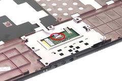
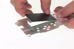
5. Remove the four screws fastening the touchpad bracket. 6. Remove the touchpad bracket (with touchpad). 7. Detach the touchpad from the touchpad bracke.t

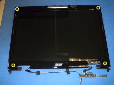
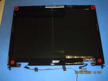
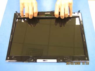
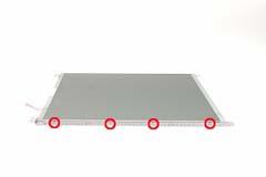
1. Remove the four screw caps as shown. 2. Remove the four screws holding the LCD bezel. 3. Then detach the LCD bezel from the LCD module.
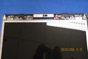
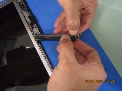
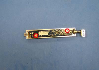
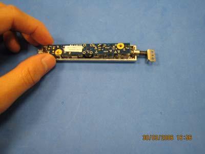
4. Remove the two screws fastening the LCD inverter. 5. Take out the LCD inverter from the LCD cover, then disconnect the LCD cable from the inverter. 6. Remove the two screws holding the digital camera to the LCD panel.
7. Detach the CCD panel from the CCD bezel assembly. 8. Disconnect digital camera to LCD cable as shown. 9. Remove the two screws fastening the CCD.
10. Take out the CCD from the CCD bezel. 11. Then remove the CCD hinge from the CCD bezel. 12. Slide the CCD latch to the right to remove the CCD latch. NOTE: The edges of the CCD latch is very fragile, please practice this step very carefully.
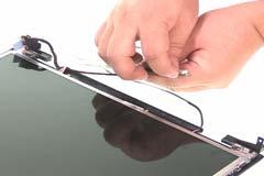


13. Take out the LCD assembly from the LCD panel. 14. Disconnect the LCD cable from the LCD. 15. Tear off the tape fastening the LCD cable and detach the LCD cable from the LCD.
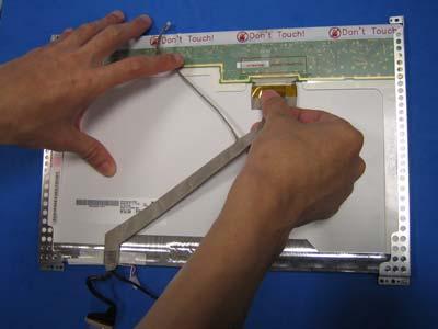
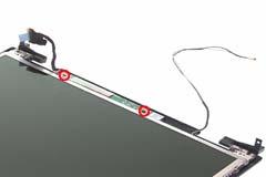
16. Remove the two screws holding the wireless antenna set to the LCD panel. 17. Take out the wireless antenna set from the LCD panel. 18. Remove the two screws holding the LCD hinges then remove the hinges.
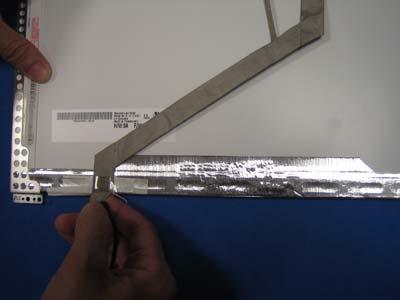
19. Remove the four screws fastening the LCD right bracket. 20. Remove the right bracket from the LCD.
21. Remove the four screws fastening the LCD left bracket. 22. Remove the left bracket from the LCD.
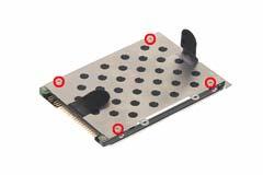
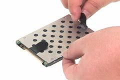
Disassembling the HDD Module
1. Remove the four screws fastening the HDD bracket. 2. Remove the HDD bracket.
Disassembling the ODD Module
1. Remove the two screws holding the ODD fix holder bracket. 2. Then remove the ODD fix holder bracket. 3. Reove the two screws fastening the ODD rail bracket then remove the rail bracket.