7 minute read
Chapter 3 Machine Disassembly and Replacement


Machine Disassembly and Replacement
This chapter contains step-by-step procedures on how to disassemble the notebook computer for maintenance and troubleshooting. To disassemble the computer, you need the following tools: Wrist grounding strap and conductive mat for preventing electrostatic discharge Small Philips screw driver Philips screwdriver Plastic flat head screw driver Tweezers NOTE: The screws for the different components vary in size. During the disassembly process, group the screws with the corresponding components to avoid mismatch when putting back the components. When you remove the stripe cover, please be careful not to scrape the cover.
Before You Begin
Before proceeding with the disassembly procedure, make sure that you do the following: 1. Turn off the power to the system and all peripherals. 2. Unplug the AC adapter and all power and signal cables from the system. 3. Remove the battery pack. NOTE: TravelMate 3000 series product uses mylar or tape to fasten the FFC/FPC/connectors/cable, you may need to tear the tape or mylar before you disconnect different FFC/FPC/connectors. NOTE: There are several types of screws used to secure bottom case and upper case assembly. The screws vary in length. Please refer the picture below, group the same type of screws together during service disassembling. Please also remember the screw location for each screw type. If you fasten the screw to the wrong location, the screw may be too long to damage the main board.
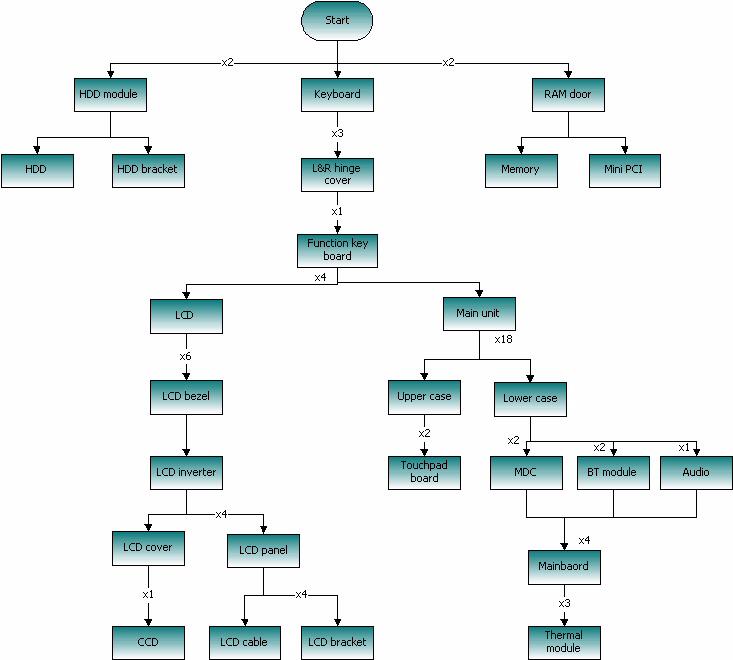
The flowchart on the succeeding page gives you a graphic representation on the entire disassembly sequence and instructs you on the components that need to be removed during servicing. For example, if you want to remove the main board, you must first remove the keyboard, then disassemble the inside assembly frame in that order.
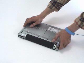
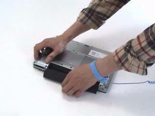
1. Release the battery lock. 2. Slide the battery latch. 3. Remove the battery pack.
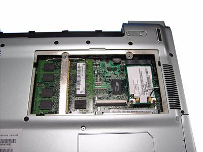
Removing the miniPCI/Memory/HDD Module/ Keyboard
Removing the miniPCI and Memory
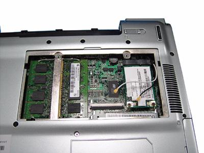
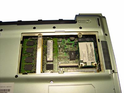
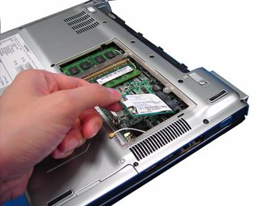
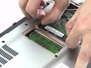
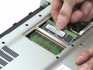
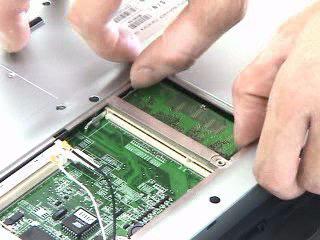
1. Remove the two screws that secure the RAM door and remove the RAM door. 2. Release the wireless antenna. 3. Remove the two screws securing the miniPCI card. 4. Press the latch on left and right side to pop out the miniPCI and remove it. 5. Press the latch on left and right side to pop out the memory and remove it. 6. Press the latch on left and right side to pop out the other memory and remove it.
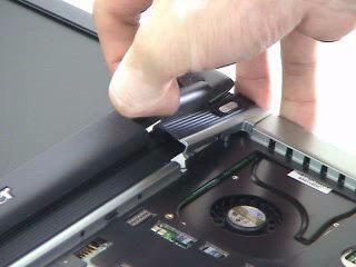
Removing the HDD
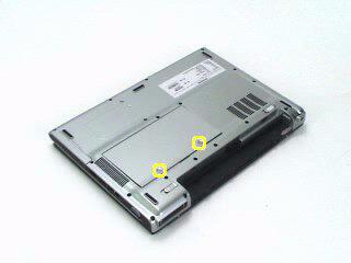
1. Remove the two screws that secure the HDD. 2. Pull the HDD out and remove it from the main unit.

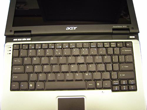
Removing the keyboard
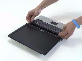
1. Open the LCD panel.
2. Press the two inner keyboard latches that secure the keyboard with flat screw driver. 3. Release another two outer keyboard latches. 4. Pull the keyboard and trun it over. 5. Disconnect the keyboard FFC from the mainboard. 6. Remove the keyboard from the main unit.
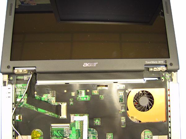
1. Disconnect the function key board FFC from the mainboard. 2. Disconnect the LCD cable from the mainboard. 3. Disconnect the touchpad board FFC from the mainboard.
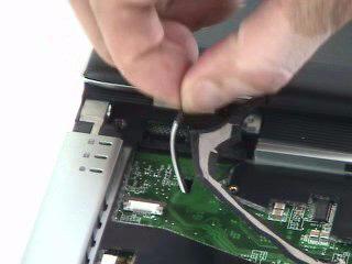
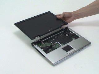
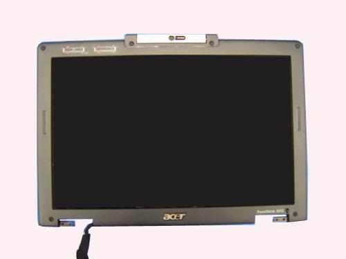
4. Remove the three screws that secure the left and right hinge cover. 5. Pull the left hinge up and slide it out as show. 6. Pull the right hinge cover up and slide it out as show. 7. Disconnect the function key board FFC from the function key board. 8. Remove the screw that secures the function key board. 9. Remove the function key board from the left hinge cover. 10. Pull the wireless antenna out. 11. Remove the two screws securing the left and right hinges. 12. Detach the LCD module from the main unit.
Function keyboard FFC LCD cable
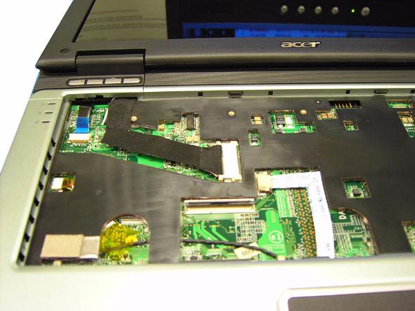
Touchpad FFC

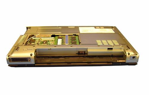
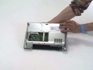
Separate upper and lower case
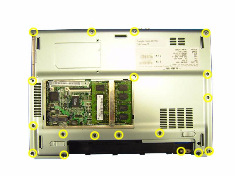
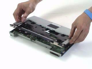
1. Turn the main unit over. 2. Remove the eighteen screws that secure the lower case. 3. Detach the upper case from the lower case assembly.
Removing the Bluetooth module
1. Tear off the mylar on the Bluetooth cable 2. Disconnect the Bluetooth cable from the mainboard. 3. Remove the two screws that secure the Bluetooth module. 4. Remove the Bluetooth module from the mainboard. 5. Disconnect the Bluetooth cable from the Bluetooth module.
Removing the MDC module
1. Tear off the mylar on the MDC cable. 2. Disconnec the MDC cable from the mainboard. 3. Remove the MDC cable from the wire groove. 4. Remove the two screws that secure the MDC board. 5. Remove the MDC board from the mainboard.
Removing the audio module
1. Remove the screw that secures the audio board. 2. Remove the audio board from the mainboard.
Removing the mainboard from lower case
1. Press the button and remove the dummy card from the PCMCIA card slot.
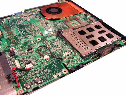
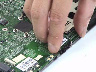
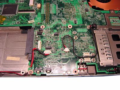
2. Disconnect the speaker cable from the mainboard. 3. Disconnect the microphone cable from the mainboard.
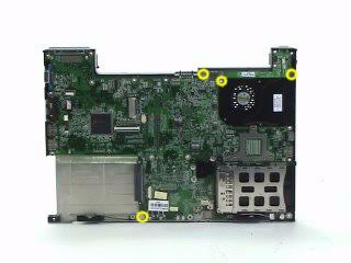
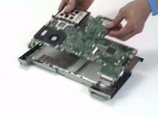
4. Remove the four screws that secure tha mainboard. 5. Detach the mainboard from the lower case. 6. Disconnect the power board cable from the mainboard and remove the power board from the mainboard.
Speaker cable Microphone cable
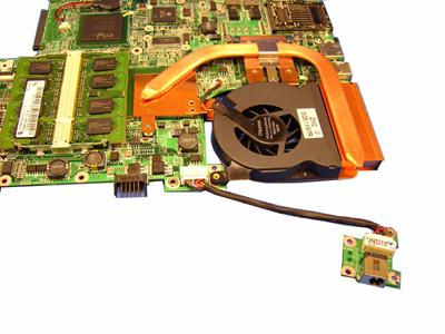
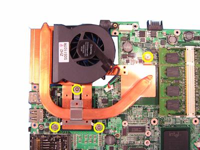
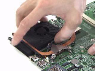
7. Remove the three screws that secure the thermal following the order 1, 2, 3. 8. Disconnect the fan cable from the mainboard. 9. Remove the thermal module from the mainboard.
10. Tear off the mylar on the touchpad board FFC. 11. Disconnect the touchpad board FFC from the touchpad board. 12. Disconnect another FFC from the touchpad board. 13. Remove the two screws that secure the touchpad board. 14. Remove the touchpad board from the upper case. 15. This completes the main unit disassembly.
1. Remove the six screw pads. 2. Remove the six screws that secure the LCD bezel.
3. Release the latches one by one. Please note that the bezel is fragile. Need to follow the following disassembly pictures from left to right.
4. Pull the bezel a little bit forward that paralleled LCD cover and remove the LCD bezel.
5. Pull the inverter board out. 6. Disconnect the LVDS cable from the inverter board. 7. Disconnect the LCD cable from the inverter board. 8. Remove the inverter board.
9. Remove the four screws that secure the LCD and disconnect the CCD cable. 10. Remove the LCD from the cover assembly. 11. Remove the screw securing the CCD. 12. Remvoe the CCD from the cover assembly.
14. Remove the two screws that secure the left LCD bracket. 15. Remove the left LCD bracket from the LCD. 16. Remove the two screws that secure the right LCD bracket. 17. Remove the right LCD bracket from the LCD.
18. Turn the LCD back. 19. Tear off the tape on theLCD cable. 20. Disconnect the LCD cable from the LCD. 21. This completes the LCD disassembly.
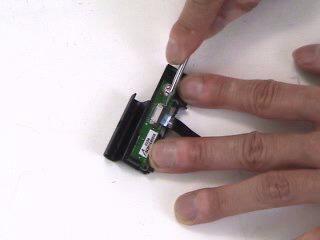
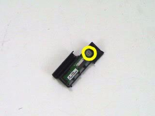
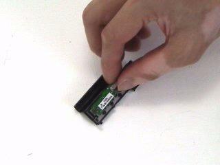
1. Remove the two screws that secure the HDD holder on on side. 2. Remove the two screws that secure the HDD holder on the other side. 3. Lift up the HDD and remove it from the HDD holder. 4. Place the HDD back to the HDD holder 5. Secure the HDD with two screws on one side. 6. This complete the HDD module disassembly and reassembly.