12 minute read
Chapter 2 System Utilities


System Utilities
BIOS Setup Utility
The BIOS Setup Utility is a hardware configuration program built into your computer’s BIOS (Basic Input/ Output System). Your computer is already properly configured and optimized, and you do not need to run this utility. However, if you encounter configuration problems, you may need to run Setup. Please also refer to Chapter 4 Troubleshooting when problem arises. To activate the BIOS Utility, press m during POST (when “Press <F2> to enter Setup” message is prompted on the bottom of screen). Press m to enter setup. The default parameter of F12 Boot Menu is set to “disabled”. If you want to change boot device without entering BIOS Setup Utility, please set the parameter to “enabled”. Press <F12> during POST to enter multi-boot menu. In this menu, user can change boot device without entering BIOS SETUP Utility.
There are six menu options: Info., Main, System Devices, Security, Boot, and Exit. Follow these instructions: To choose a menu, use the cursor left/right keys (zx). To choose a parameter, use the cursor up/down keys ( wy). To change the value of a parameter, press por q. A plus sign (+) indicates the item has sub-items. Press e to expand this item. Press ^ while you are in any of the menu options to go to the Exit menu. In any menu, you can load default settings by pressing t. You can also press u to save any changes made and exit the BIOS Setup Utility.
NOTE: You can change the value of a parameter if it is enclosed in square brackets. Navigation keys for a particular menu are shown on the bottom of the screen. Help for parameters are found in the Item Specific Help part of the screen. Read this carefully when making changes to parameter values. Please note that system information is subject to different models.
NOTE: The system information is subject to different models.
Parameter Description
CPU Type This field shows the CPU type and speed of the system. IDE1 Model Name This field shows the model name of HDD installed on primary IDE master. IDE1 Serial Number This field displays the serial number of HDD installed on primary IDE master. IDE2I Model Name This field displays the mofel name of devices installed on secondary IDE master. The hard disk drive or optical drive model name is automatically detected by the system. IDE2 Serial Number This field shows the serial number of devices installed on secondary IDE master. System BIOS ver Displays system BIOS version. VGA BIOS Ver This field displays the VGA firmware version of the system. KBC Ver This field shows the keyboard Serial Number This field displays the serial number of this unit. Asset Tag Number This field displays the asset tag number of the system. Product Name This field shows product name of the system. Manufacturer Name This field displays the manufacturer of this system.
Parameter
Description
UUID Number This will be visible only when an internal LAN device is presenting. UUID=32bytes
The Main screen displays a summary of your computer hardware information, and also includes basic setup parameters. It allows the user to specify standard IBM PC AT system parameters.
NOTE: The screen above is for your reference only. Actual values may differ.
ItemSpecificHelp
SystemTime: [13:51:27] SystemDate: [10/17/2006]
SystemMemory: 640KB ExtendedMemory: VideoMemory: 1022MB 128MB <Tab>,<Shift-Tab>,or <Enter>selectsfield. Showssystembasememorysize Showsextendedmemorysize
QuietBoot: [Enabled] Powerondisplay: [Auto] Networkboot [Enabled] F12BootMenu [Disabled] D2DRecovery [Enabled]
The table below describes the parameters in this screen. Settings in boldface are the default and suggested parameter settings.
Parameter Description Format/Option
System Time Sets the system time. The hours are displayed with 24-hour format.
Format: HH:MM:SS (hour:minute:second) System Time System Date Sets the system date. Format MM/DD/YYYY (month/day/ year) System Date
System Memory This field reports the memory size of the system. Memory size is fixed to 640MB Extended Memory This field reports the memory size of the extended memory in the system. Extended Memory size=Total memory size-1MB VGA Memory Shows the VGA memory size. VGA Memory size=64/128MB Quiet Boot Determines if Customer Logo will be displayed or not; shows Summary Screen is disabled or enabled. Enabled: Customer Logo is displayed, and Summary Screen is disabled. Disabled: Customer Logo is not displayed, and Summary Screen is enabled. Option: Enabled or Disabled
Power on display Auto: During power process, the system will detect if any display device is connected on external video port. If any external display device is connected, the power on display will be in CRT (or projector) only mode. Otherwise it will be in LCD only mode. Both: Simultaneously enable both the integrated LCD screen and the system’s external video port (for an external CRT or projector). Option: Auto or Both
Network Boot Enables, disables the system boot from LAN (remote server). Option: Enabled or Disabled
F12 Boot Menu Enables, disables Boot Menu during POST. Option: Disabled or Enabled D2D Recovery Enables, disables D2D Recovery function. The function allows the user to create a hidden partition on hard disc drive to store operation system and restore the system to factory defaults. Option: Enabled or Disabled
NOTE: The sub-items under each device will not be shown if the device control is set to disable or auto. This is because the user is not allowed to control the settings in these cases.
The Main screen displays a summary of your computer hardware information, and also includes basic setup parameters. It allows the user to specify standard IBM PC AT system parameters.
NOTE: The screen above is for your reference only. Actual values may differ.
Serialport: [Auto]
Parallelport: Mode: [Enabled] [ECP]
InfraredPort(FIR): [Enabled] ItemSpecificHelp
ConfigureserialportAusing options:
BIOSorOSchooses configuration (OSControlled)
Displayedwhencontrolled byOS
The table below describes the parameters in this screen. Settings in boldface are the default and suggested parameter settings.
Description Option
Serial Port Configure serial port A using options: [Disabled]: No configuration [Enabled]: User configuration [Auto]: BIOS or OS chooses configuration (OS Controlled) Displayedd when controlled by OS Infrared Port Configure serial port B using options: [Disabled]: No configuration [Enabled]: User configuration [Auto]: BIOS or OS chooses configuration (OS Controlled) Displayedd when controlled by OS Disabled Enabled
Auto
Disabled Enabled
Auto
Parallel Port Configure serial port B using options: [Disabled]: No configuration [Enabled]: User configuration [Auto]: BIOS or OS chooses configuration (OS Controlled) Displayedd when controlled by OS Disabled Enabled
Auto
Mode Set the mode for the parallel port Output only Bi-directional EPP ECP
NOTE: The sub-items under each device will not be shown if the device control is set to disable or auto. This is because the user is not allowed to control the settings in these cases.
The Security screen contains parameters that help safeguard and protect your computer from unauthorized use.
NOTE: Please refer to “Remove HDD/BIOS Password” section if you need to know how to remove HDD/BIOS Password.
Information Main PhoenixBIOSSetupUtility
Security Boot
SupervisorPasswordIs: Clear UserPasswordIs: HDD0Password Clear Clear
SetSupervisorPassword SetUserPassword SetHDD0Password
PasswordonBoot [Enter] [Enter] [Enter]
[Disabled] Exit
ItemSpecificHelp
SupervisorPassword controlsaccessesofthe wholesetuputility. Itcanbeusedto bootupwhenPassword onbootisenabled.
The table below describes the parameters in this screen. Settings in boldface are the default and suggested parameter settings.
Parameter Description
Option
User Password is Shows the setting of the user password. Clear or Set Supervisor Password is Shows the setting of the Supervisor password Clear or Set Set User Password Press Enter to set the user password. When user password is set, this password protects the BIOS Setup Utility from unauthorized access. The user can enter Setup menu only and does not have right to change the value of parameters. Set Supervisor Password Press Enter to set the supervisor password. When set, this password protects the BIOS Setup Utility from unauthorized access. The user can not either enter the Setup menu nor change the value of parameters. Primary HardDisk Security Enables or disables primary hard disk security function. Password on Boot Defines whether a password is required or not while the events defined in this group happened. The following sub-options are all requires the Supervisor password for changes and should be grayed out if the user password was used to enter setup. Disabled or Enabled
NOTE: When you are prompted to enter a password, you have three tries before the system halts. Don’t forget your password. If you forget your password, you may have to return your notebook computer to your dealer to reset it.
Setting a Password
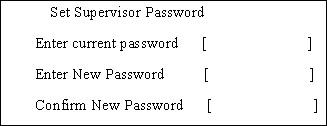
Follow these steps as you set the user or the supervisor password: 1. Use the w andy keys to highlight the Set Supervisor Password parameter and press the e key. The
Set Supervisor Password box appears:
2. Type a password in the “Enter New Password” field. The password length can not exceeds 8 alphanumeric characters (A-Z, a-z, 0-9, not case sensitive). Retype the password in the “Confirm New
Password” field.
IMPORTANT:Be very careful when typing your password because the characters do not appear on the screen. 3. Press e. After setting the password, the computer sets the User Password parameter to “Set”. 4. If desired, you can opt to enable the Password on boot parameter. 5. When you are done, press u to save the changes and exit the BIOS Setup Utility.
Follow these steps: 1. Use the w and y keys to highlight the Set Supervisor Password parameter and press the e key. The
Set Password box appears:
2. Type the current password in the Enter Current Password field and press e. 3. Press e twice without typing anything in the Enter New Password and Confirm New Password fields.
The computer then sets the Supervisor Password parameter to “Clear”. 4. When you have changed the settings, press u to save the changes and exit the BIOS Setup Utility.
Changing a Password
1. Use the w and y keys to highlight the Set Supervisor Password parameter and press the e key. The
Set Password box appears:
2. Type the current password in the Enter Current Password field and press e. 3. Type a password in the Enter New Password field. Retype the password in the Confirm New Password field. 4. Press e. After setting the password, the computer sets the User Password parameter to “Set”. 5. If desired, you can enable the Password on boot parameter. 6. When you are done, press u to save the changes and exit the BIOS Setup Utility.
If the verification is OK, the screen will display as following.

If the current password entered does not match the actual current password, the screen will show you the Setup Warning.

If the new password and confirm new password strings do not match, the screen will display the following message.

This menu allows the user to decide the order of boot devices to load the operating system. Bootable devices includes the distette drive in module bay, the onboard hard disk drive and the CD-ROM in module bay.
Bootpriorityorder: 1: IDE0: WDCWD200EB-(PM) 2: IDE1: SAMSUNGCD-ROM 3: 1394CD-ROM: 4: NetworkBoot: 5: USBHDD: 6: USBCD-ROM: 7: USBFloppy: 8: USBKey:
Excludedfrombootorder: ItemSpecificHelp
Keysusedtovieworconfigure device: UseUpandDownarrowsto selectadevice. <+>and<->movesthedevice upordown. <f>and<r>specifiesthe devicefixedorremovable. <x>excludeorincludethe devicetoboot. <Shift+1>enablesordisables adevice. <1-4>Loadsdefaultboot sequence.
The Exit screen contains parameters that help safeguard and protect your computer from unauthorized use.
The table below describes the parameters in this screen.
ExitSavingChanges ExitDisardingChanges LoadSetupDefaults DiscardChanges SaveChanges ItemSpecificHelp
ExitSystemSetupandsave yourchangestoCMOS.
Parameter Description
Exit Saving Changes Exit System Setup and save your changes to CMOS. Exit Discarding Changes Exit utility without saving setup data to CMOS. Load Setup Default Load default values for all SETUP item. Discard Changes Load previous values from CMOS for all SETUP items. Save Changes Save Setup Data to CMOS.
The BIOS flash memory update is required for the following conditions: New versions of system programs New features or options Restore a BIOS when it becomes corrupted. Use the Phlash utility to update the system BIOS flash ROM. NOTE: If you do not have a crisis recovery diskette at hand, then you should create a Crisis Recovery Diskette before you use the Phlash utility. NOTE: Do not install memory-related drivers (XMS, EMS, DPMI) when you use the Phlash. NOTE: Please use the AC adaptor power supply when you run the Phlash utility. If the battery pack does not contain enough power to finish BIOS flash, you may not boot the system because the BIOS is not completely loaded. Fellow the steps below to run the Phlash. 1. Prepare a bootable diskette. 2. Copy the flash utilities to the bootable diskette. 3. Then boot the system from the bootable diskette. The flash utility has auto-execution function.
This section provide you with removing HDD/BIOS method:
Remove HDD Password:
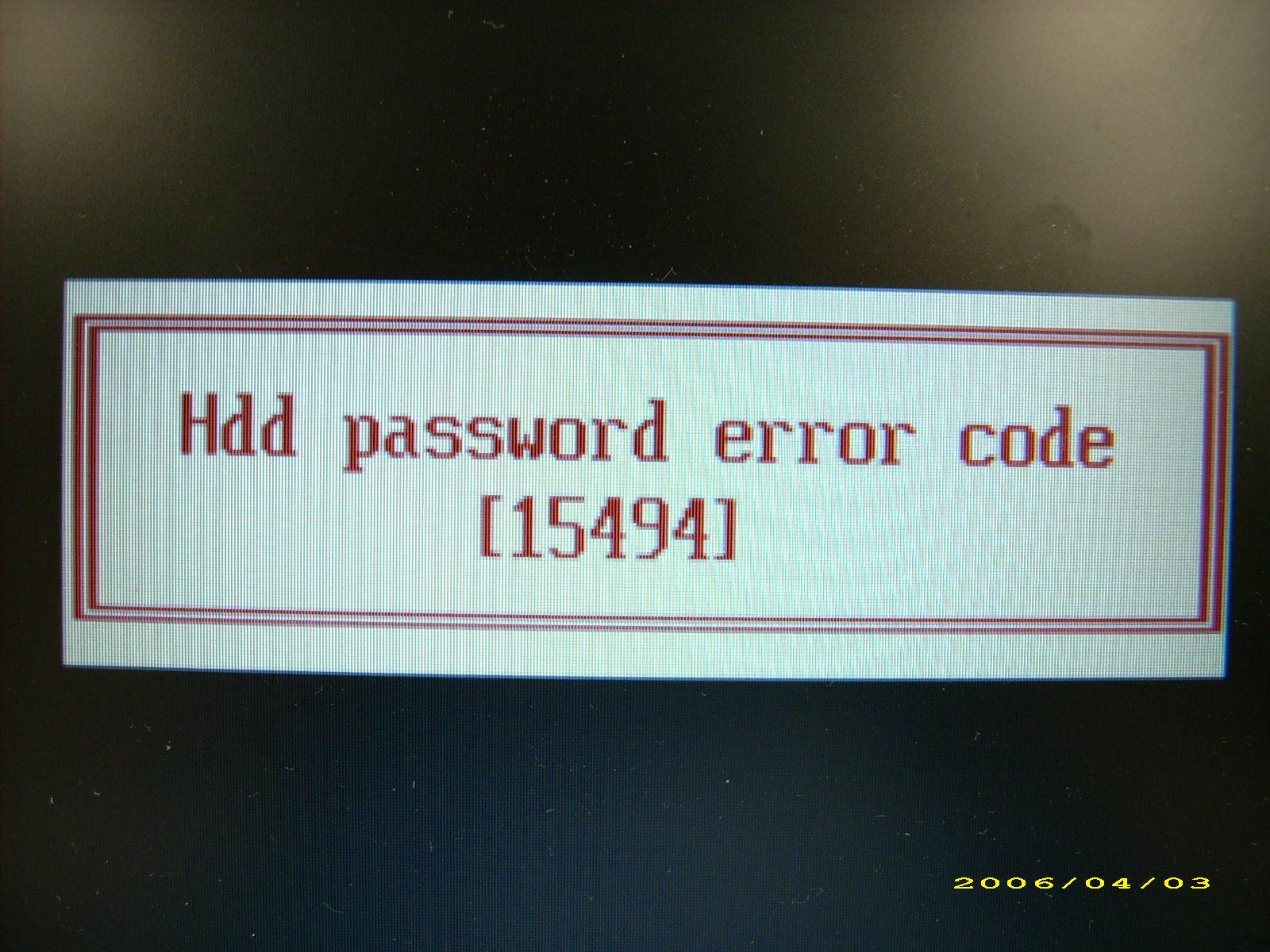
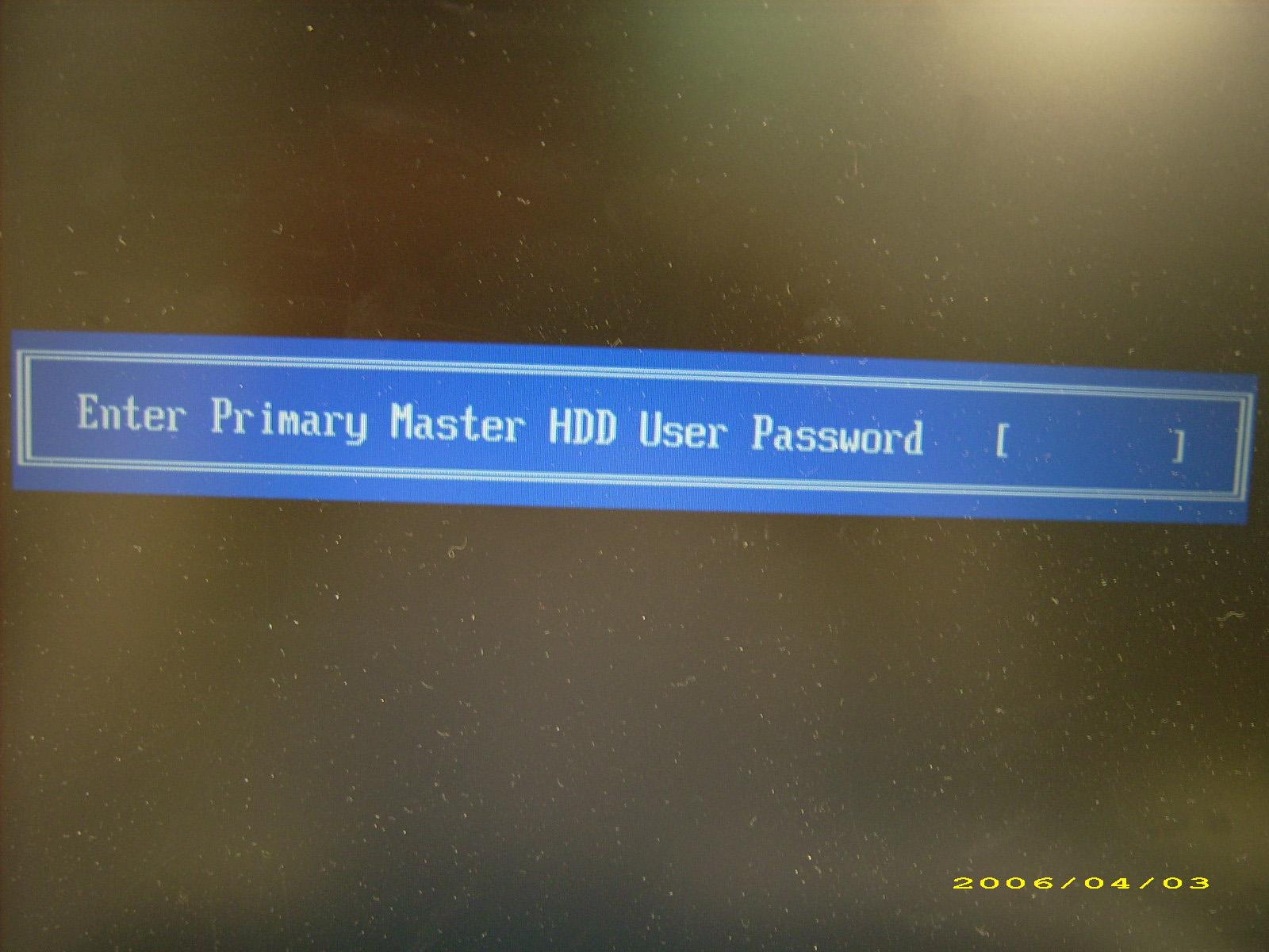
If you key in wrong HDD password for three time, “HDD password error code” would display on the screen. See the image below.
If you need to solve HDD password locked problem, you can run HDD_PW.EXE
1. Key in “hdd_pw 15494 0” 2. Select “2” 3. Choose one upper-case string
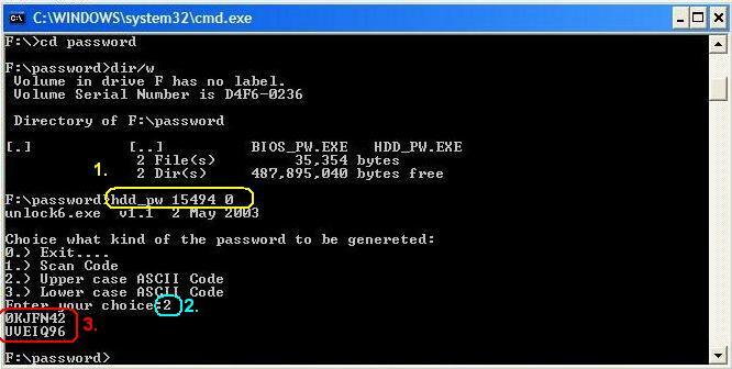
Reboot system and key in “0KJFN42” or “UVEIQ96” to HDD user password.
Remove BIOS Password:
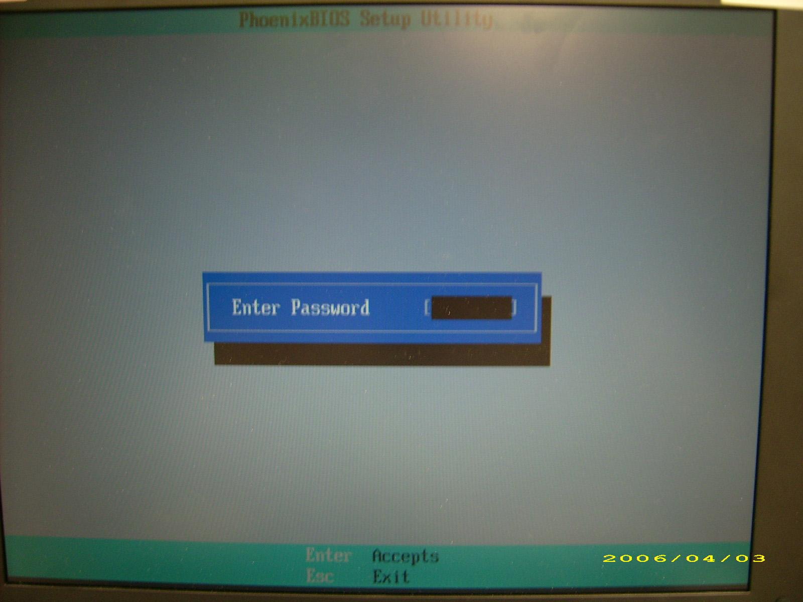
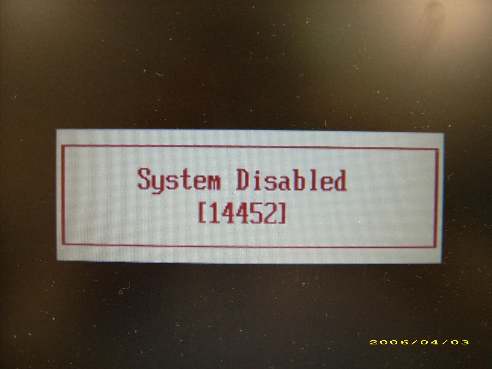
If you key in wrong Supervisor Password for three time, “System Disabled” would display on the screen. See the image below.
If you need to solve BIOS password locked problem, you can run BIOS_PW.EXE
1. Key in “bios_pw 14452 0” 2. Choose one upper-case string
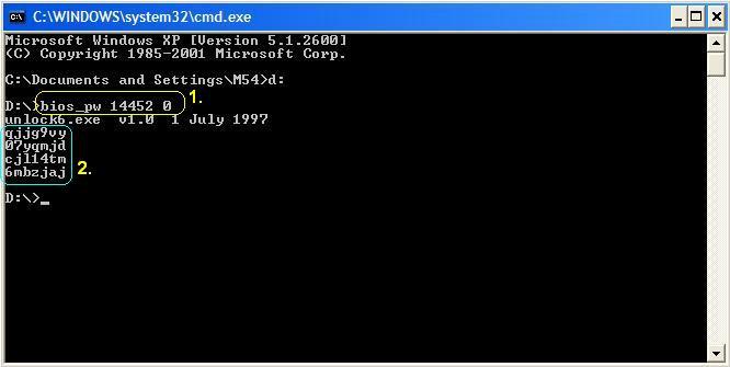
Reboot the system and key in “qjjg9vy” or “07yqmjd” to BIOS user password.