1 minute read
Chapter 5 Jumper and Connector Locations


Jumper and Connector Locations
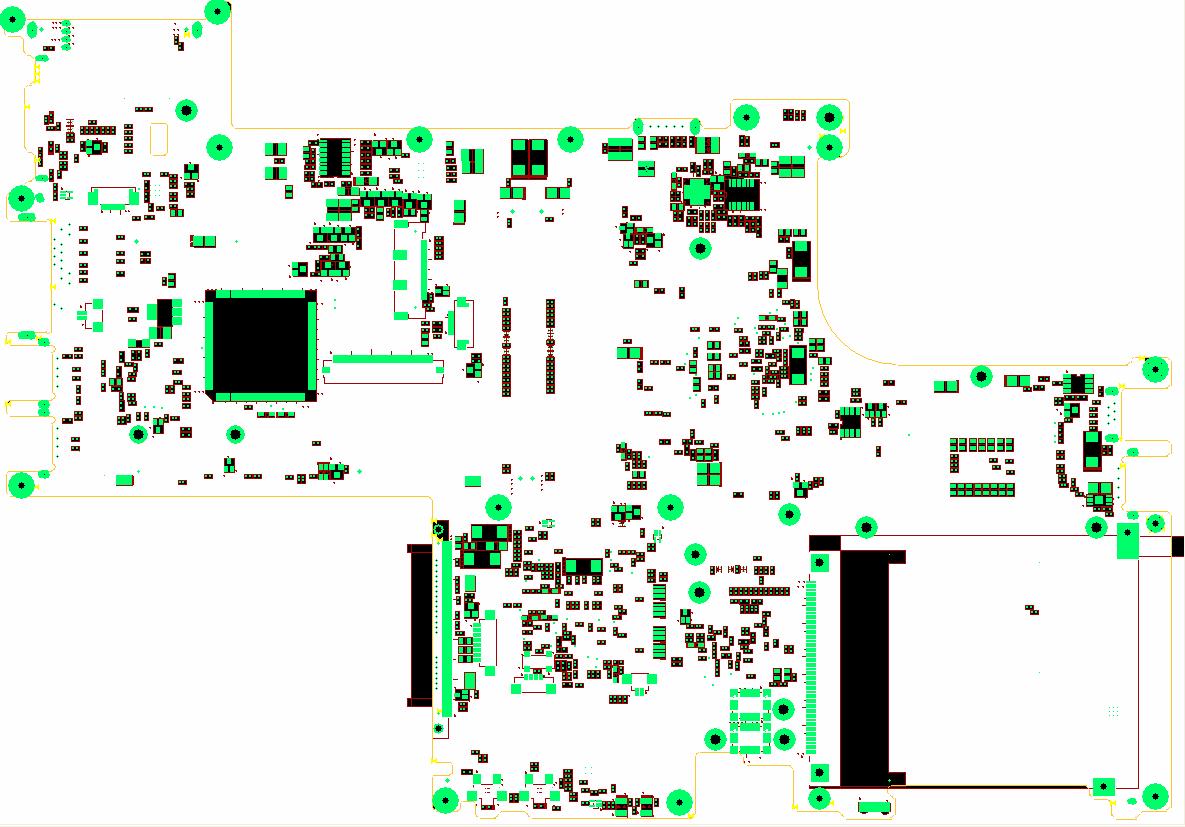
Top View
14 15 16
13 17
12
11 18 19
20 21
10
9
7 6 8
3
4
5 1
2
1 PCMCIA Connector 12 Keyboard Connector 2 FIR 13 EC Controller 3 Modem Board Connector 14 MDC Connector 4 Audio Board Connector 15 SW Board Connector 5 Power/Charger LED 16 3V/5V Converter IC 6 Wireless Switch 17 LCD/CCD Connector 7 Bluetooth Switch 18 Touchpad Connector 8 Internal Microphone Connector 19 Battery Connector 9 Internal Speaker Connector 20 Charger IC 10 Bluetooth Cable Connector 21 +1.05V Converter IC 11 SATA HDD Connector
22
17
16
15 21
18 23
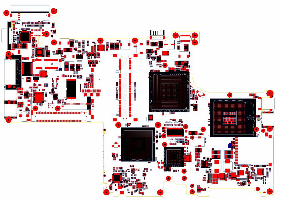
20 H5(Ness2) Bot-side
Layout Placement
Description
24
14
13 19
11
12 10
8
6 25 26
9 27
7
5 4 28
29
3 30 31
32
1
2
1 5-in1 Card Reader Connector 17 2 CPU Power IC 18 3 +1.5V Power IC 19 Mini Card Connector 4 Card Bus IC 20 DVI (CH7307C) IC 5 Audio AMP 21 SIO (PC87383) IC 6 Audio Codec AL883 22 VGA Connector 7 South Bridge ICH7-M 23 EZ dock Connector 8 RTC Battery 24 DDRII Power IC 9 G Sense 25 Battery Connector 10 DDRII soDIMM socket 26 DC-in Connector 11 BIOS 27 North Bridge 945GM 12 Mini PCI Connector 28 FAN Connector 13 LAN Controller 29 Clock Genarator 14 LAN Switch 30 CPU 15 USB Connector 31 1394 Connector 16 USB Connector 32 USB Connector