
9 minute read
Removal and Installation of Supply Pump


[7] Removal of base plate (2-1)
Loosen the hexagon socket head bolts (33) and remove the base plate (2-1).
Caution: When removing the base plate (2-1), observe the following precautions.
•The base plate (2-1) is pushed upwards by the springs (26). For this reason, loosen the hexagon socket head bolts (33) evenly when loosening. •Positioning knock pins (27) are mounted between the base plate (2-1) and main unit.
For this reason, pull the base plate (2-1) straight off in alignment with the center axis of the motor when removing it so that it does not become stuck with the knock pins (27). If it becomes stuck, lightly strike the base plate (2-1) with a plastic hammer to put the knock pins (27) in the correct position, and then remove the base plate (2-1). •When removing the base plate (2-1), the valve plate (5) is attached to the base plate (2-1). The valve plate (5) sliding surface is easily scratched, so be careful not to let the valve plate (5) fall.
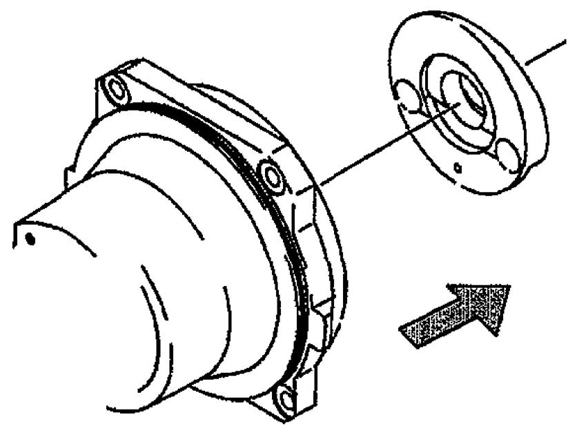
[8] Removal of valve plate (5)
Remove the valve plate (5) on the motor (cylinder block (4)).
Caution: When removing the valve plate (5), observe the following precaution.
•The cylinder block (4) and valve plate (5) sliding surfaces are easily scratched. If the sliding surface is scratched, prescribed capabilities will disappear, so prevent scratching from occurring.

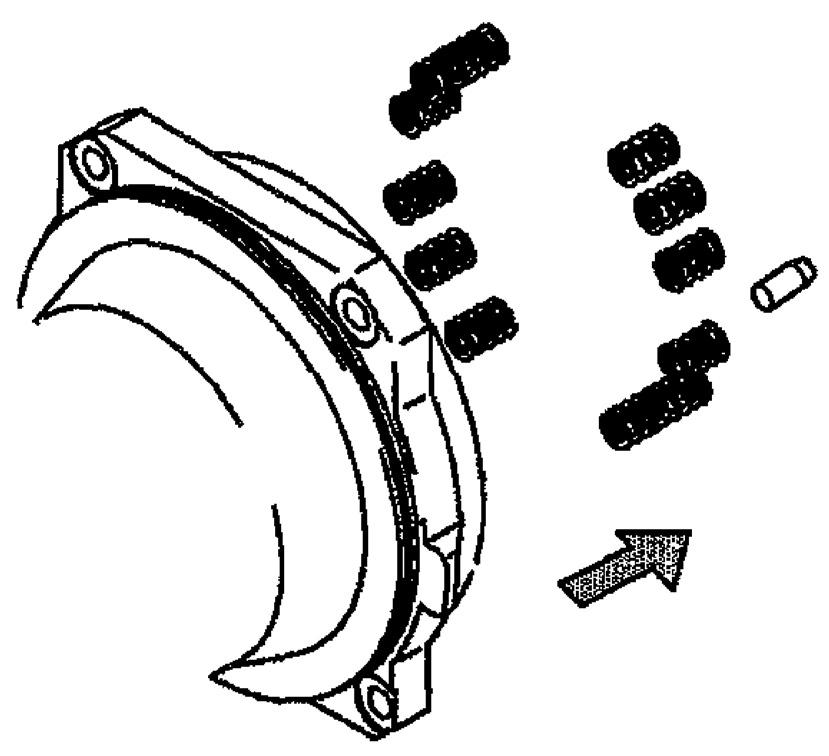
[9] Removal of O-rings, knock pin and spring
Remove the O-rings (29), (30) and the knock pins (27). Also, remove the springs (26).
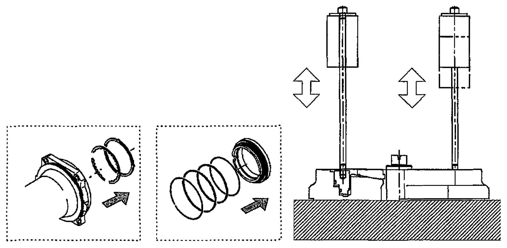
[10]Removal of brake piston (21)
Screw the brake piston removal jig (special tool 1) into the 2 knock pin hole threaded sections of the brake piston (21), grasp the grip section of the jig, hit upward, gradually make the brake piston (21) float up and remove. After removing the brake piston (21), remove the disk plates (19) and friction plates (18), (20), and remove the Orings (22), (24) and backup rings (23), (25) from the brake piston (21).
Caution: When removing the brake piston (21), observe the following precaution. a.Fasten the case (1) securely. Unless it is fastened securely, the operation of the brake piston (21) pulling up may move the case and cause injury and damage to motor parts.

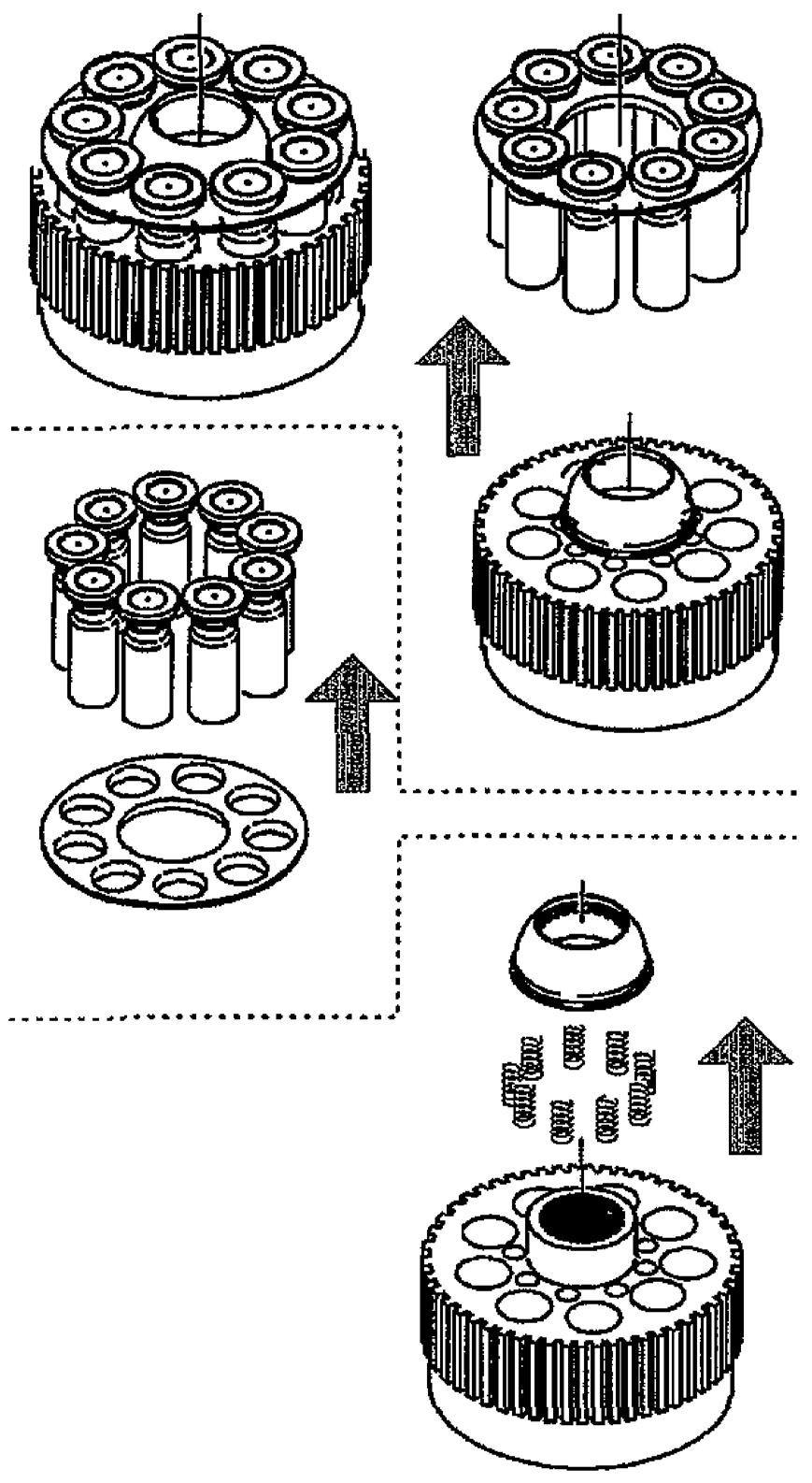
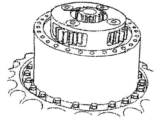
[11]Removal of cylinder block (4) assembly
Remove the cylinder block (4), piston assemblies (6), retainer holder (8), and retainer plate (7) from the case (1).
Caution:
When removing the cylinder block (4) assembly, observe the following precautions. •Grasp the cylinder block (4) with both hands and lightly rotate it left and right to slowly remove the cylinder block and all the parts up to and including the retainer plate (7). •Be careful not to scratch the cylinder block (4) sliding surface against the valve plate (5). If this surface is scratched, the machine will no longer display prescribed capabilities. •Be careful not to scratch the piston assembly (6) shoe sliding surfaces. If this surface is scratched, the machine will no longer display prescribed capabilities. [12]Disassembly of cylinder block (4) assembly •Mark the piston assemblies (6) and cylinder block (4) with permanent ink so that parts can be reassembled in the exact same configuration, and remove the piston assemblies (6) and retainer plate (7) from the cylinder block (4). •Mark the piston assemblies (6) and retainer plate (7) with permanent ink so that parts can be reassembled in the exact same configuration, and remove the piston assemblies (6) from the retainer plate (7). •Remove the retainer holder (8) from the cylinder block (4) and remove the springs (17) from the cylinder block (4).

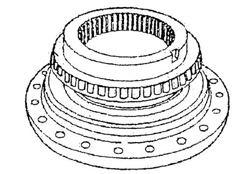
[13]Removal of swash plate (9)
Remove the swash plate (9) from the case (1).
Caution: When removing the swash plate (9), observe the following precautions.
•Be careful not to scratch the swash plate (9) sliding surface. If this surface is scratched, the machine will no longer display prescribed capabilities. • Piston assemblies (11) and steel balls (10) may be attached to the swash plate (9). When any are attached, be careful not to let the piston assemblies (11) or steel balls (10) fall.
[14]Removal of piston assemblies (11) and steel balls (10)
Remove the piston assemblies (11) from the case (1) and remove the springs (12).
Remove the steel balls (10) from the case (1).
Caution: The steel balls (10) are difficult to remove, so use the following procedure to do this.
•With the steel balls (10) mounted in the case (1), use white kerosene or thinner to degrease. •Use a magnet to remove the steel balls (10) from the case (1).
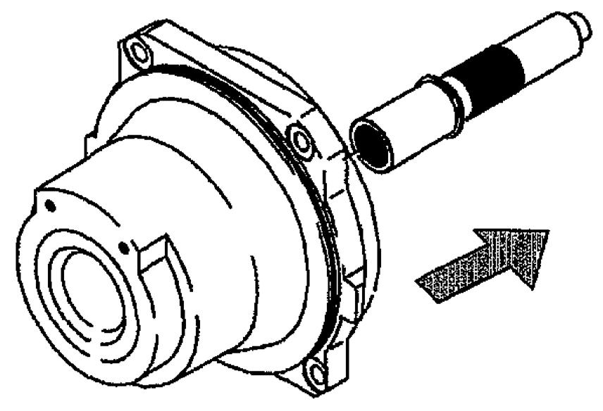
[15]Removal of shaft (3)
Remove the shaft (3) from the case (1).
Caution:
When removing the shaft (3), observe the following precautions. •Be careful not to scratch the spline on the shaft (3). •Be careful not to scratch the sliding section of the shaft (3) oil seal (28). Scratching this surface may cause oil leaking.
[16]Parts storage
This completes the disassembly. Place disassembled parts in plastic bags in a cool, dark and dry location after cleaning the parts and applying anti-rust oil. If parts are stored in a hot, moist location, rust will develop even if anti-rust oil is applied. Also store them in a way so that dust does not collect on them.

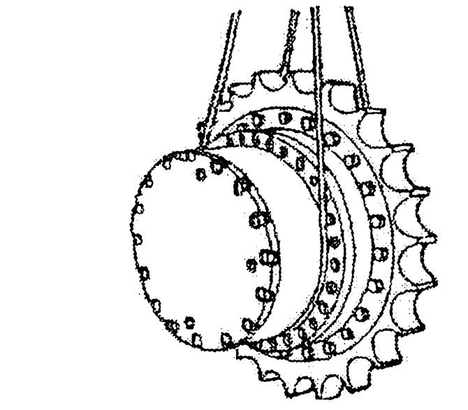
[17]Removal of reduction gear
Remove lines related to the hydraulic motor and remove the reduction gear from the machine body.
Danger: When lifting a product for disassembly, no one must enter underneath the product. The product falling may cause personal injury.
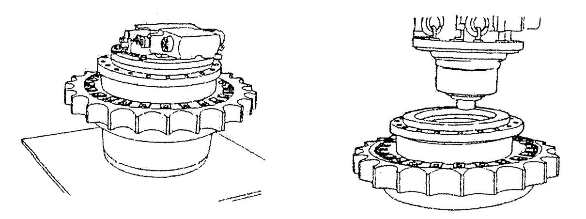
[18]Disassembly of inside of reduction gear and removal of hydraulic motor a.Loosen the plugs (36) attached to the cover (32) halfway and bleed off the pressure in the reduction gear. After the pressure in the reduction gear is bled off, remove the plugs (36), then drain the lubricating oil. Caution: Be careful that if the plug is loosened all at once, the hot lubricating oil might spray out.
b.Remove the 4 hexagon socket head bolts (38) linking the reduction gear and the hydraulic motor, then remove the hydraulic motor (*1) from the reduction gear.
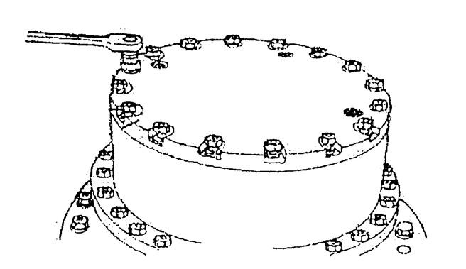
c.Remove the 20 hexagon socket head bolts (35) and the cover (32).
d.Remove the sun gear A (20) and the 1st stage carrier assembly (*2).

e.Remove the 2nd stage sun gear B (21) from the 2nd stage carrier assembly (*4), install the jig (the eyebolt M10 (*3)) on the 2nd stage carrier assembly, and remove the 2nd stage carrier assembly with a liftcrane.
f. Remove the 3rd stage sun gear C (22) from the 3rd stage carrier assembly.
g.Install the jig (the eyebolt M10 (*5)) on the ring gear (23), lift up with the liftcrane, then remove the parallel pins (31) and ring gear (23) from the drum case (30).
h.Install the jig (the eyebolt M10 (*7)) on the 3rd stage carrier assembly (*6), lift up with the liftcrane, then remove the 3rd stage carrier assembly.
i. Remove the 2 bolts with washers (29), then remove the lock plate (28).
j.Put the jig (*8) in the nut (27) hole, then remove the nut (27).


k.Press the motor case (24) spline side end with the press with the drum case (30) installation surface as the receiving surface to remove the reduction gear side roller bearing (26).
l. Remove the floating seal (25) from the drum case (30). In the same way, also remove the floating seal (25) from the motor case (24). •Be careful not to damage the seal surface of the floating seal and O-ring. m.Remove the motor case (24) side roller bearing (26). •Investigate the condition of each part in this state. If there is any wear, abnormality, or the like, replace the affected part with a new one. (See Table 7 Usage limit criteria.) [19]Disassembly of carrier assembly 1) Drive in the spring pin (6) so that they fit within shaft A (5), and remove shaft A (5) from carrier A (1).
2) Remove planetary gear A (2), needle bearing (3), thrust washer (4), and washer (7) from the carrier assembly. •Disassemble the 2nd stage and the 3rd stage in the same way.
In the 3rd stage, there is no needle bearing to remove.


4.Maintenance standards (1) Motor parts maintenance standards Table 6 shows maintenance standards for motor parts. Check each part according to the maintenance standards in Table 6. When a permissible limit value has been exceeded or is near being exceeded, perform part repair or replacement according to repair and solution procedures.
Table 6. Motor parts maintenance standards
Applicable part Inspection and measurement location
1. Shoe sliding surface
Piston assembly (6) 2. Piston outer diameter
3. Piston outer diameter and cylinder block (4) bore inner diameter Permissible limit value Repair, solution procedure
0.8 a degree of roughness Or the surface is rough and there is scratching at least 0.02 mm deep.
1.2 a degree of roughness Or the surface is rough and there is scratching at least 0.02 mm deep.
Gap 0.060 mm Lap the shoe sliding surface (#1000). If the scratching cannot be removed, replace the cylinder block (4), valve plate (5) and piston assembly (6).
Replace the cylinder block (4), valve plate (5), and piston assembly (6).
4. Shoe ball backlash 0.4 mm of backlash
Cylinder block (4) 1. Sliding surface against the valve plate
2. Bore inner diameter
3. Bore inner diameter and piston assembly (6) outer diameter
4. Shaft bonding section spline
Valve plate (5) 1. Sliding surface
Retainer plate (7) Retainer holder (8) 1. Sliding surface 0.8 a degree of roughness Or the surface is rough and there is scratching at least 0.02 mm deep. 1.6 a degree of roughness Or the surface is rough and there is scratching at least 0.02 mm deep. Replace the cylinder block (4), valve plate (5), and piston assembly (6).
Gap 0.060 mm
Diameter between parts φ46.987 Diameter of measurement pin φ2.743 Or breaking damage is occurring. 0.8 a degree of roughness There is scratching at least 0.02 mm deep on the sliding surface. Or seizing is occurring. There is abnormal wear on the sliding surface.
0.8 a degree of roughness There is scratching at least 0.02 mm deep on the sliding surface. Or seizing is occurring. Replace the cylinder block (4), valve plate (5), and piston assembly (6).
Replace the cylinder block (4), valve plate (5), and piston assembly (6).
Replace the retainer plate (7) and retainer holder (8).
