3 minute read
Removal and Installation of Alternator


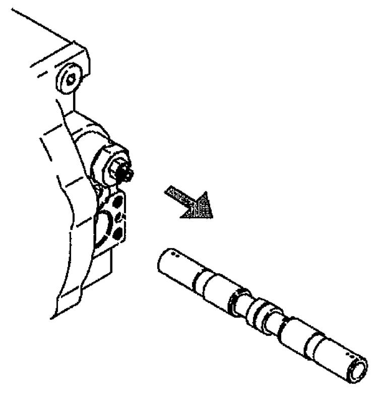
[2] Removal of spool assembly (2-2)
Lightly press the end of the spool assembly (2-2) and eject one part of the spool assembly (2-2) out from the base plate (21). Next, while grabbing the end of the spool assembly (2-2) by hand and rotating, remove the spool assembly (2-2) from the base plate (2-1).
Caution:
The spool assembly (2-2) and base plate (2-1) are fit together with a very small gap.
For this reason, observe the following precautions when working. •Do not try to force out the spool assembly (2-2) with extreme force if the spool assembly (2-2) becomes stuck when it is being removed. If it is forced out, this could scratch the inner diameter surface of the base plate (2-1) hole or the outer diameter surface of the spool assembly (2-2). If it becomes stuck, do as follows.
Lightly hit the end surface of the spool assembly (2-2) with a plastic hammer to once insert it into the base plate (2-1). After this, check that the spool assembly (2-2) moves smoothly and try again to remove it while rotating it. •Do not perform disassembly of the spool assembly (2-2) if it is not necessary. Disassembly can cause scratching on the outer diameter surface of the spool assembly.
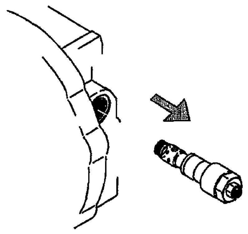
When disassembly is necessary, contact our company. [3] Removal of relief valves (2-7)
Loosen the plug (2-7-6) and remove the relief valves (2-7).
Caution:
The relief valves (2-7) is at a set pressure.
The motor driving force and braking force are both determined by this set pressure.
For this reason, do not perform the following actions. •Loosen the nut (2-7-9) and do not tamper with the locking screw (2-7-8). If this part is tampered with, the set pressure of the relief valve will change and the machine will no longer display prescribed capabilities. •Do not perform disassembly of the relief valve. The set pressure will change and the machine will no longer display prescribed capabilities.
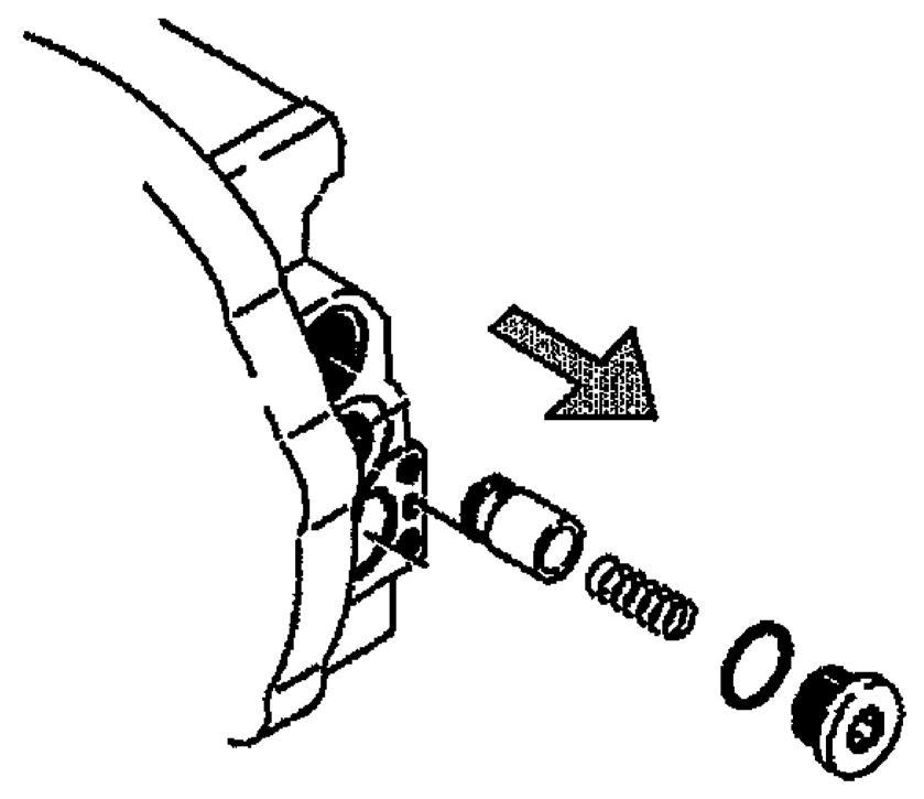
[4] Removal of check valves (2-19)
Next, loosen the plugs (2-21) and remove the plugs (2-21), springs (2-20) and check valves (2-19).
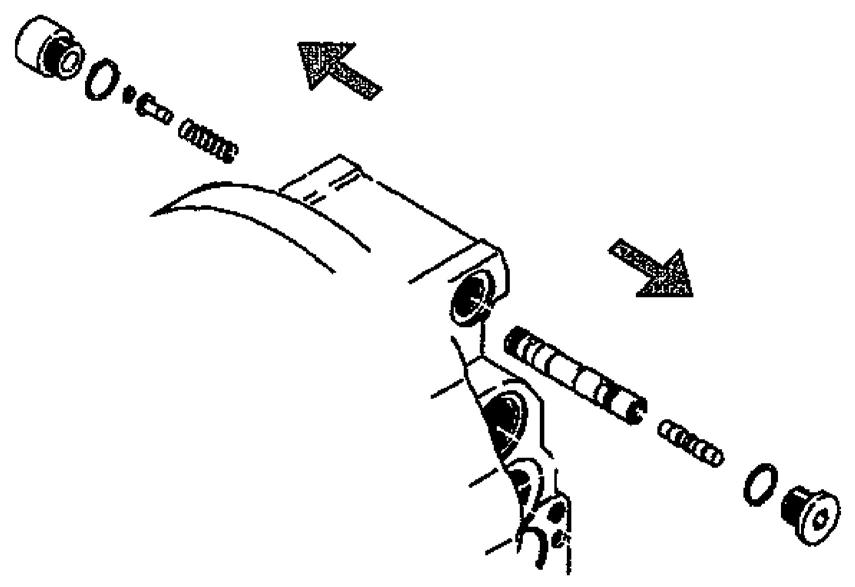
[5] Removal of valve assembly (2-9)
Loosen the plugs (2-14), (2-17) and remove the plugs (2-14), (2-17), spring guide (2-16), washer (2-18), and spring (213). Next, lightly press the end of the valve assembly (2-9) and eject one part of the valve assembly (2-9) out from the base plate (2-1). Next, while grabbing the end of the valve assembly (2-9) by hand and rotating, remove from the base plate (2-1).
Some motor models do not use (2-16) (217) or (2-18).
Caution: The valve assembly (2-9) and base plate (2-1) are fit together with a very small gap. For this reason, observe the following precautions when working.
•Do not try to force out with extreme force if the valve assembly (2-9) becomes stuck when it is being removed. If it is forced out, this could scratch the inner diameter surface of the base plate (2-1) hole or the outer diameter surface of the valve assembly (2-9). If it becomes stuck, do as follows.
Lightly hit the end surface of the valve assembly (2-9) with a plastic hammer to once insert it into the base plate (2-1). After this, check that the valve assembly (2-9) moves smoothly and try again to remove it while rotating it. •Do not perform disassembly of the valve assembly (2-9) if it is not necessary. When disassembly is necessary, contact our company.
[6] Do not remove the plugs (2-25) if it is not necessary. (2-23) and (2-24) are caulked so that they do not come loose. Do not perform disassembly.