15 minute read
29 thru 28


c. Remove the spring, detent ball and retainer from the valve body at the forward and reverse valve. d. Remove forward-reverse valve after stop clip has been removed from the valve body. e. Remove inching control valve by first removing stop clip, then seal, springs and spool. f . Remove cap at regulator valve and then the spring and spool. g. Remove cap at dump valve and then the spring and spool. Inspect all valves and springs and cavities in valve body for wear, damage, or presence of dirt. Clean all parts thoroughly before reassembly and replace oil seals and gaskets at reassembly.
SUGGESTED ASSEMBLY PRECAUTIONS
1. Make sure a gasket is in place at the suction inlet opening and not damaged when installing the oil filter screen.
2. Machined reliefs in idler shaft cap must be positioned down so that the oil cap can drain into the housing. 3. As gears and bearings are being installed they should be coated with lubricant and it should be made certain that they rotate freely. 4. Be sure match marks are aligned on the oil pump assembly with the housing, and rear collector ring with the housing, or oil passages will not be open. 5. Be sure snap rings are properly installed and thoroughly seated. 6. Use a new gasket when replacing the valve body assembly.
NOTE: Refer to Trouble Diagnosis, pages 16 and 17, when overhauling or repairing.
SERVICE POLICY (Optional)
In the event of a T12 Transmission failure and for the convenience of those customers desiring this service, we have an exchange policy on the T12 Transmission. We will furnish a new or rebuilt T12 Transmission and ship to the customer on a conditional invoice basis. When the old transmission is received at our plant, transportation charges , prepaid, this conditional invoice will be cancelled We will then rebuild the returned T12 Transmission and invoice the customer for the actual parts and labor required to put the returned transmission in the same condition as the one shipped.
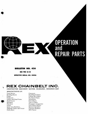
WARNER GEAR MODEL T 12 TRANSMISSION
OIL ENTERING CONVERTER
OIL LEAVING CONVERTER LIFTER HOLES
CONVERTER CHARGING PR. TAP
REV. CLUTCH PR. TAP
MAIN PR. TAPS
OIL LEVEL DIPSTICK MAIN PR. REG. VALVE
INCHING VALVE (LOCKED OUT)
DUMP VALVE
F-R SELECTOR VALVE
FORWARD CLUTCH PR. TAPS
INPUT PUMP
COOLER BYPASS VALVE
DRAIN PLUG
CONVERTER OIL OUT TO COOLER
CONVERTER OIL OUT PR. TAP PROVISION FOR EXTERNALLY INED S SPL FLANGELIP
FIGURE 11 EXTERNAL NOMENCLATURE
LUBE PR. TO CLUTCH ASSEMBLY
COOLER RETURN
BYPASS LINE FROM MAIN PR. REG. VALVE
REMOVAL AND REPAIR OF THE ROCKWELL PH312 DIFFERENTIAL
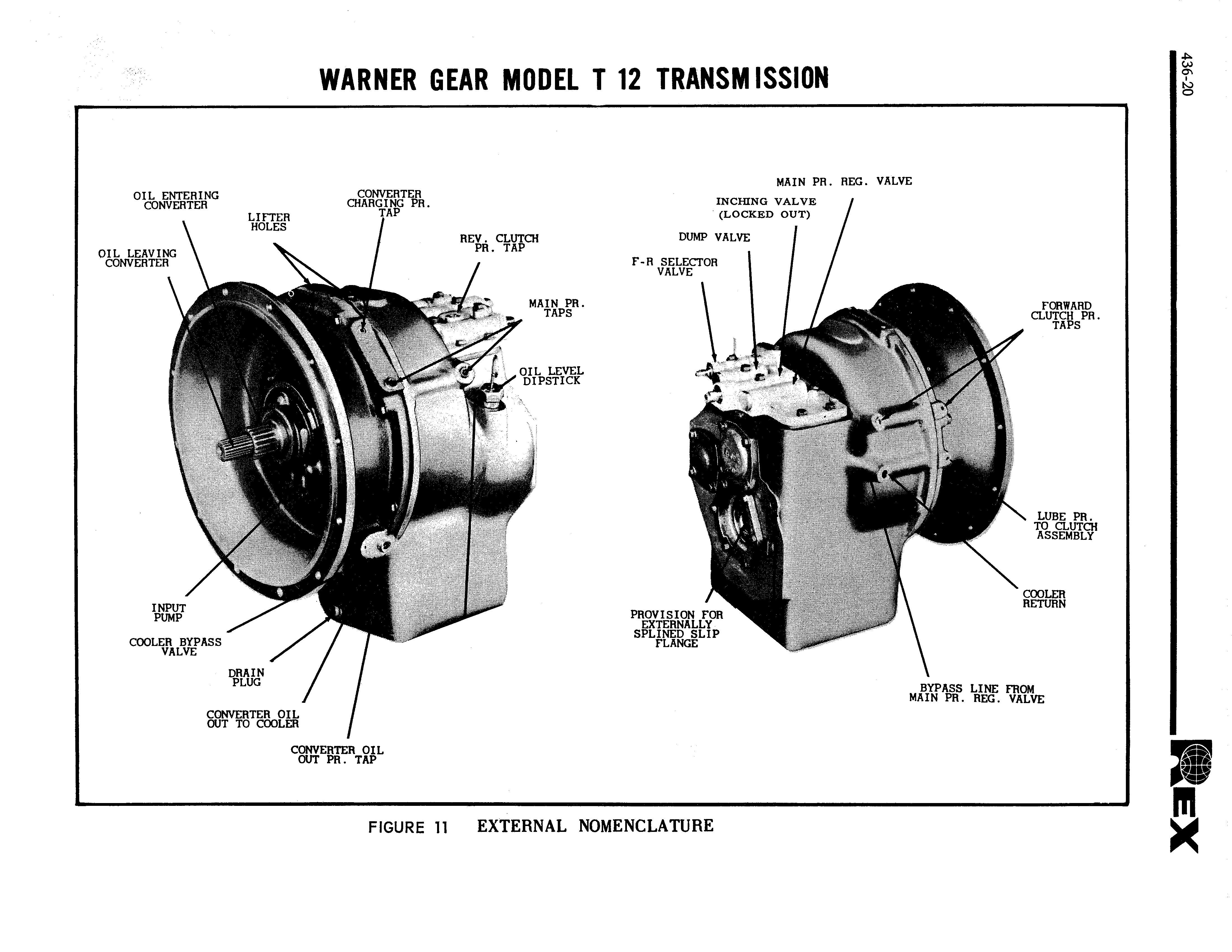
The removal and repair of this differential should be made in a machine shop with adequate facilities to per- form a major overhaul. The following general outline will aid in preparation for removal of the differential. For additional reference refer to the repair parts section for various components. 1. Refer to Figures 12, 13 and 14A. Drain oil from the differential and the two chain drive cases. Remove hood, fuel tank and floor plate.
T-12 TRANS
DIFFERENTIAL
BELLY PLATE BOTTOM COVER
FIGURE 12
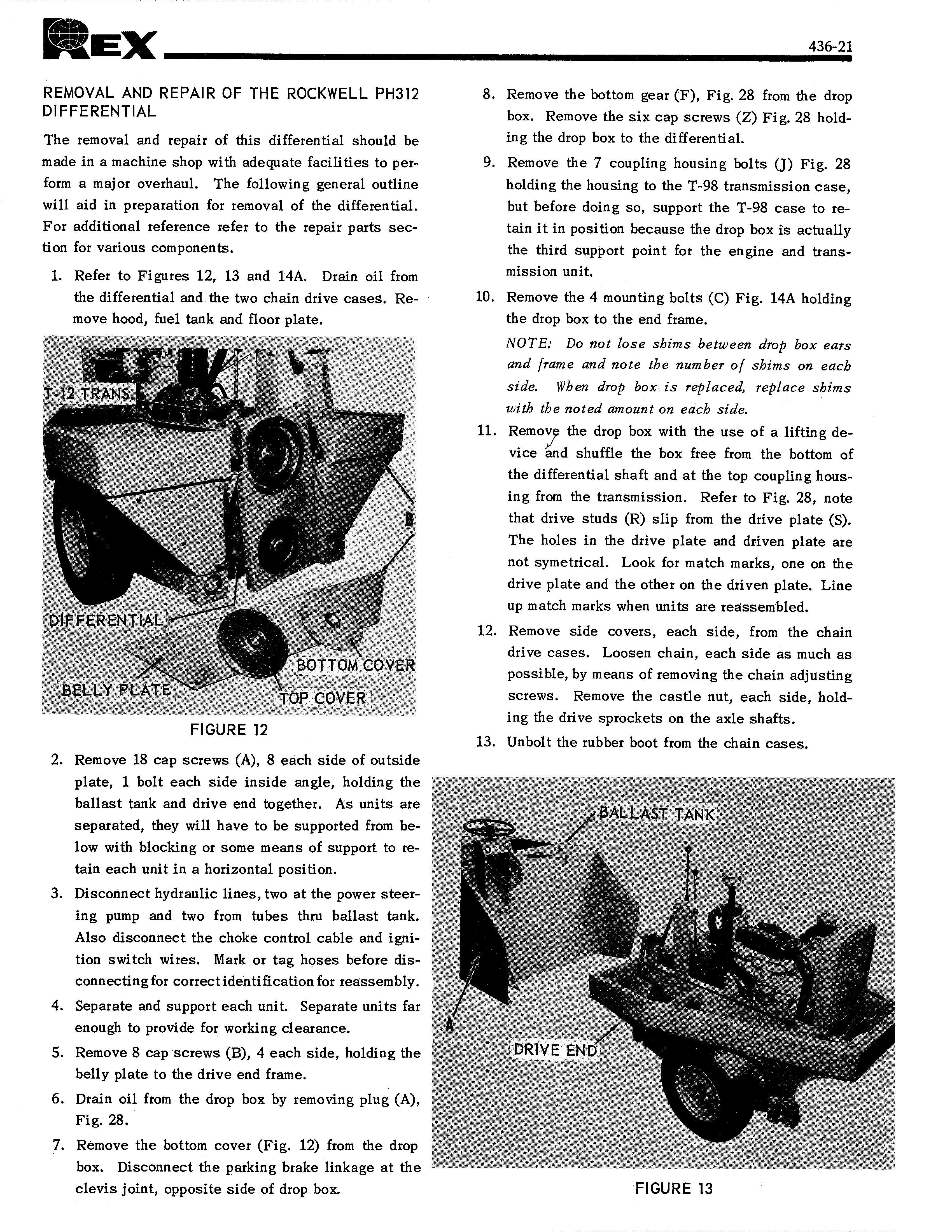
2. Remove 18 cap screws (A), 8 each side of outside plate, 1 bolt each side inside angle, holding the ballast tank and drive end together. As units are separated, they will have to be supported from below with blocking or some means of support to retain each unit in a horizontal position. 3. Disconnect hydraulic lines, two at the power steering pump and two from tubes thru ballast tank.
Also disconnect the choke control cable and ignition switch wires. Mark or tag hoses before disconnecting for correct identification for reassembly. 4. Separate and support each unit. Separate units far enough to provide for working clearance. 5. Remove 8 cap screws (B), 4 each side, holding the belly plate to the drive end frame. 6. Drain oil from the drop box by removing plug (A),
Fig. 28. 7. Remove the bottom cover (Fig. 12) from the drop box. Disconnect the parking brake linkage at the clevis joint, opposite side of drop box. 8. Remove the bottom gear (F), Fig. 28 from the drop box. Remove the six cap screws (Z) Fig. 28 holding the drop box to the differential. 9. Remove the 7 coupling housing bolts (J) Fig. 28 holding the housing to the T-98 transmission case, but before doing so, support the T-98 case to retain it in position because the drop box is actually the third support point for the engine and transmission unit. 10. Remove the 4 mounting bolts (C) Fig. 14A holding the drop box to the end frame.
NOTE: Do not lose shims between drop box ears and frame and note the number of shims on each side. When drop box is replaced, replace shims with the noted amount on each side.
11. Remove the drop box with the use of a lifting device and shuffle the box free from the bottom of the differential shaft and at the top coupling housing from the transmission. Refer to Fig. 28, note that drive studs (R) slip from the drive plate (S).
The holes in the drive plate and driven plate are not symetrical. Look for match marks, one on the drive plate and the other on the driven plate. Line up match marks when units are reassembled. 12. Remove side covers, each side, from the chain drive cases. Loosen chain, each side as much as possible, by means of removing the chain adjusting screws. Remove the castle nut, each side, holding the drive sprockets on the axle shafts. 13. Unbolt the rubber boot from the chain cases.
BAL. LAST"TANK
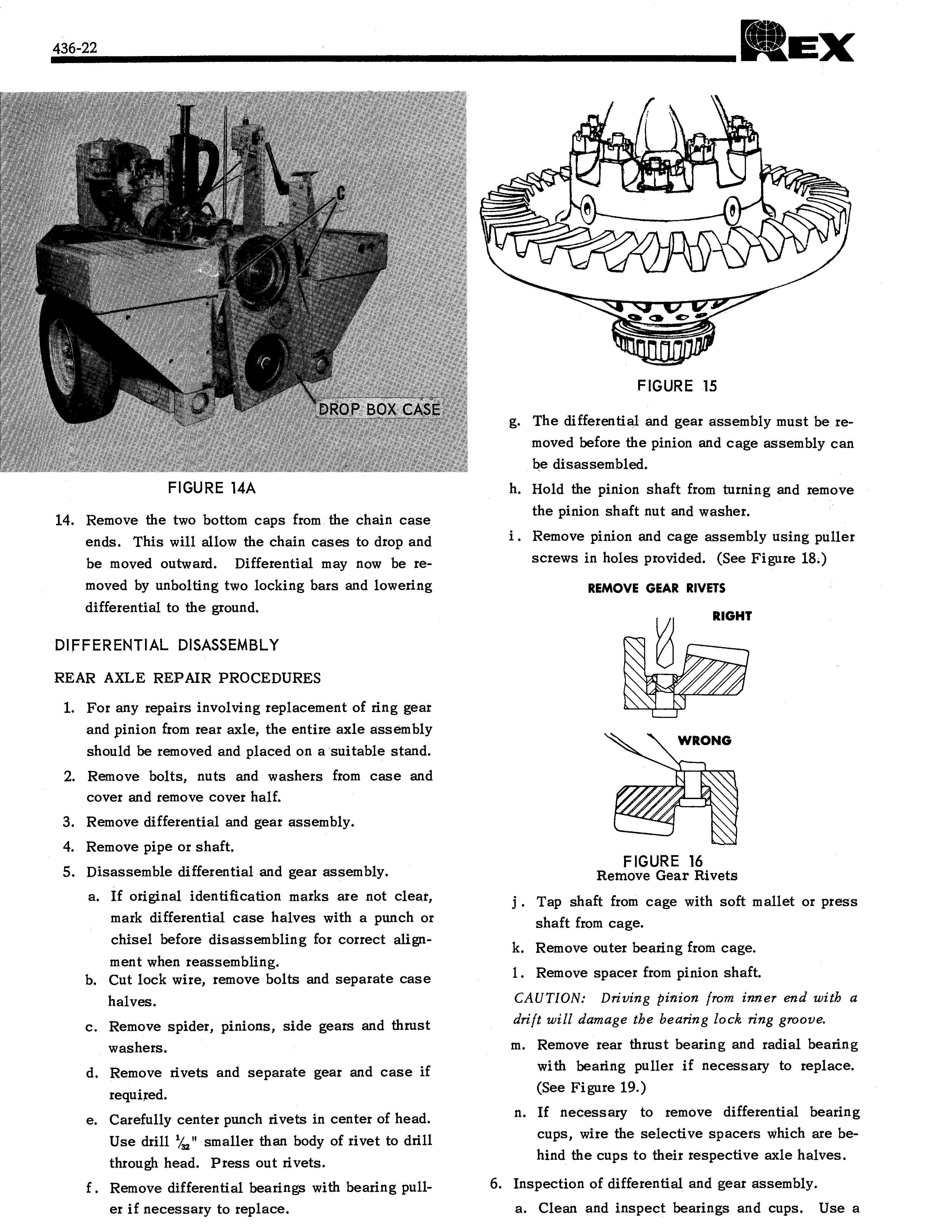
DROP BOX CASE
FIGURE 14A
14. Remove the two bottom caps from the chain case ends. This will allow the chain cases to drop and be moved outward. Differential may now be removed by unbolting two locking bars and lowering differential to the ground.
DIFFERENTIAL DISASSEMBLY
REAR AXLE REPAIR PROCEDURES
1. For any repairs involving replacement of ring gear and pinion from rear axle, the entire axle assembly should be removed and placed on a suitable stand. 2. Remove bolts, nuts and washers from case and cover and remove cover half. 3. Remove differential and gear assembly. 4. Remove pipe or shaft. 5. Disassemble differential and gear assembly. a. If original identification marks are not clear, mark differential case halves with a punch or chisel before disassembling for correct alignment when reassembling. b. Cut lock wire, remove bolts and separate case halves. c. Remove spider, pinions, side gears and thrust washers. d. Remove rivets and separate gear and case if required. e. Carefully center punch rivets in center of head. Use drill 113 " smaller than body of rivet to drill through head. Press out rivets. f . Remove differential bearings with bearing puller if necessary to replace.
FIGURE 15
g. The differential and gear assembly must be removed before the pinion and cage assembly can be disassembled. h. Hold the pinion shaft from turning and remove the pinion shaft nut and washer. i . Remove pinion and cage assembly using puller screws in holes provided. (See Figure 18.)
REMOVE GEAR RIVETS
FIGURE 16 Remove Gear Rivets
Tap shaft from cage with soft mallet or press shaft from cage. k. Remove outer bearing from cage. 1. Remove spacer from pinion shaft.
CAUTION: Driving pinion from inner end with a drift will damage the bearing lock ring groove.
m. Remove rear thrust bearing and radial bearing with bearing puller if necessary to replace. (See Figure 19.) n. If necessary to remove differential bearing cups, wire the selective spacers which are behind the cups to their respective axle halves. 6. Inspection of differential and gear assembly. a. Clean and inspect bearings and cups. Use a
16 18 20 19 2 21 23 26 30 31
29 34
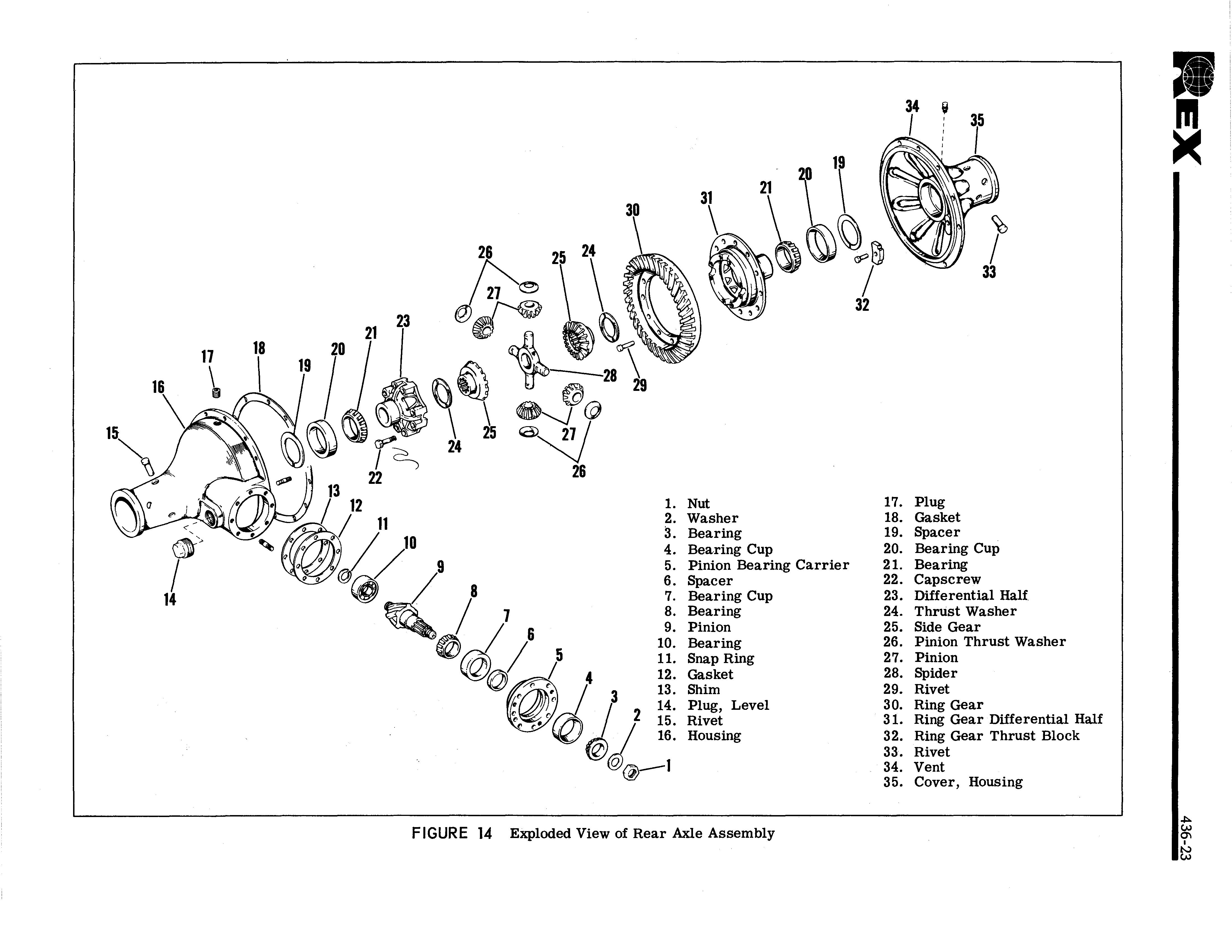
1. Nut 2. Washer 3. Bearing 4. Bearing Cup 5. Pinion Bearing Carrier 6. Spacer 7. Bearing Cup 8. Bearing 9. Pinion 10. Bearing 11. Snap Ring 12. Gasket 13. Shim 14. Plug, Level 15. Rivet 16. Housing
FIGURE 14 Exploded View of Rear Axle Assembly 17. Plug 18. Gasket 19. Spacer 20. Bearing Cup 21. Bearing 22. Capscrew
23. Differential Half .
24. Thrust Washer 25. Side Gear 26. Pinion Thrust Washer 27. Pinion 28. Spider 29. Rivet 30. Ring Gear 31. Ring Gear Differential Half 32. Ring Gear Thrust Block 33. Rivet 34. Vent 35. Cover, Housing
solution of kerosene or diesel fuel oil or suitable solvent. Never use gasoline or hot cleaning tank methods.
They may easily mutilate or distort component
parts.
e. Inspect gears for wear or damage. Gears which are pitted, galled, worn or broken through case hardening should be replaced. When necessary to replace either the pinion or gear, the gear set must be replaced. These gears are matched to assure quietness and satisfactory service.
Unmatched pinion and gear will not render satisfactory tone or gear life.
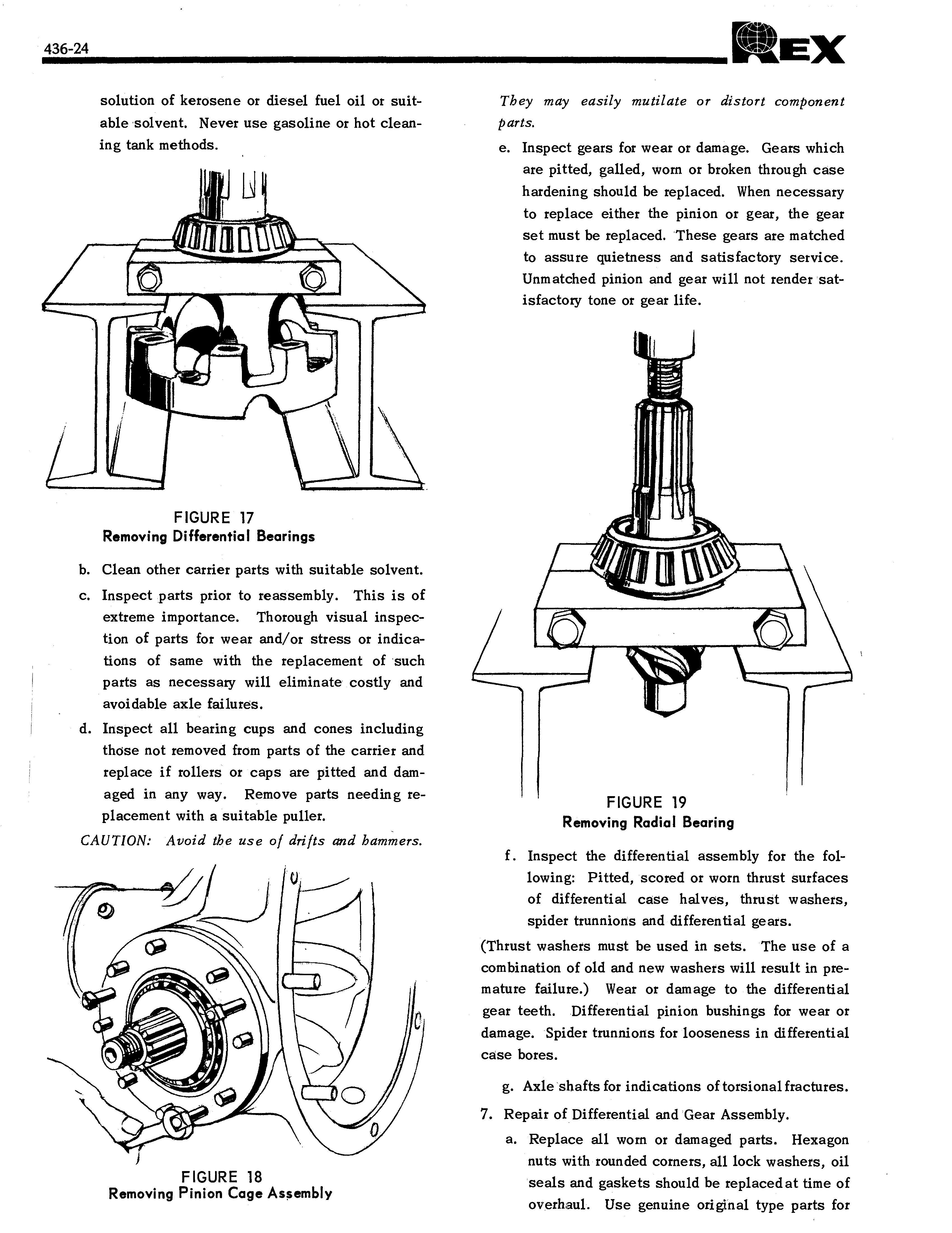
FIGURE 17
Removing Differential Bearings
b. Clean other carrier parts with suitable solvent. c. Inspect parts prior to reassembly. This is of extreme importance. Thorough visual inspection of parts for wear and/or stress or indications of same with the replacement of such parts as necessary will eliminate costly and avoidable axle failures. d. Inspect all bearing cups and cones including those not removed from parts of the carrier and replace if rollers or caps are pitted and damaged in any way. Remove parts needing replacement with a suitable puller.
CAUTION: Avoid the use of drifts and hammers.
FIGURE 19 Removing Radial Bearing
f . Inspect the differential assembly for the following: Pitted, scored or worn thrust surfaces of differential case halves, thrust washers, spider trunnions and differential gears. (Thrust washers must be used in sets. The use of a combination of old and new washers will result in premature failure.) Wear or damage to the differential gear teeth. Differential pinion bushings for wear or damage. Spider trunnions for looseness in differential case bores.
g. Axle shafts for indications of torsional fractures. 7. Repair of Differential and Gear Assembly. a. Replace all worn or damaged parts. Hexagon nuts with rounded corners, all lock washers, oil seals and gaskets should be replaced at time of overhaul. Use genuine original type parts for
replacement service. Even non-standard gaskets can be troublesome because of variations in thickness and compressibility. Replace axle and final drive housing breathers as required. b. Remove nicks, burrs and mars from machined or ground surfaces. Threads must be clean and free to obtain accurate adjustment and correct torque. A fine mill file or india stone is suited for this purpose. Studs must be right prior to reassembly. c. When assembling component parts, use a press
where necessary. Avoid hammering!
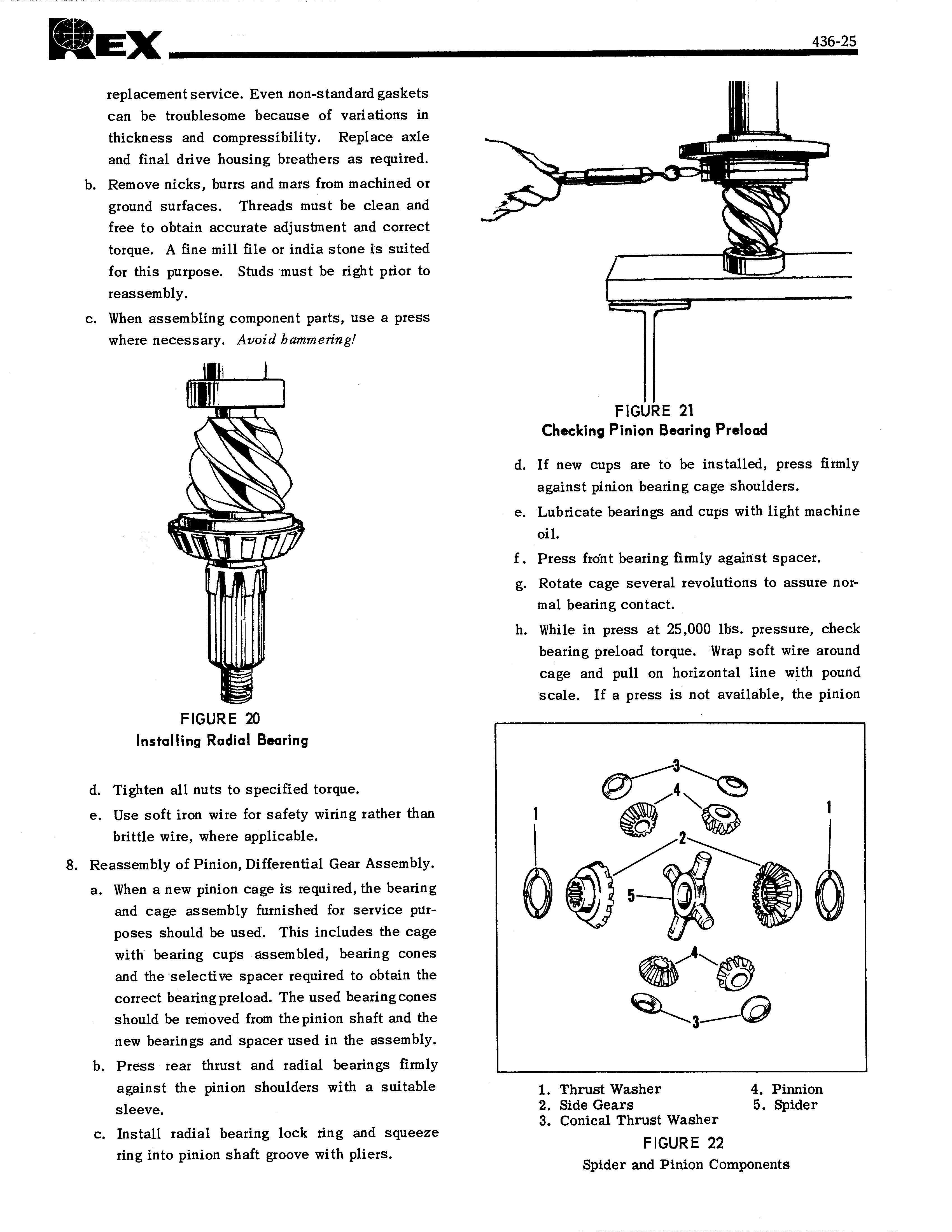
FIGURE 20 Installing Radial Bearing
d. Tighten all nuts to specified torque. e. Use soft iron wire for safety wiring rather than brittle wire, where applicable. 8. Reassembly of Pinion, Differential Gear Assembly. a. When a new pinion cage is required, the bearing and cage assembly furnished for service purposes should be used. This includes the cage with bearing cups assembled, bearing cones and the selective spacer required to obtain the correct bearing preload. The used bearing cones should be removed from the pinion shaft and the new bearings and spacer used in the assembly. b. Press rear thrust and radial bearings firmly against the pinion shoulders with a suitable sleeve. c. Install radial bearing lock ring and squeeze ring into pinion shaft groove with pliers.
FIGURE 21 Checking Pinion Bearing Preload
d. If new cups are to be installed, press firmly against pinion bearing cage shoulders. e. Lubricate bearings and cups with light machine oil. f. Press front bearing firmly against spacer. g. Rotate cage several revolutions to assure normal bearing contact. h. While in press at 25,000 lbs. pressure, check bearing preload torque. Wrap soft wire around cage and pull on horizontal line with pound scale. If a press is not available, the pinion
1. Thrust Washer 4. Pinnion 2. Side Gears 5. Spider 3. Conical Thrust Washer FIGURE 22 Spider and Pinion Components
nut may be installed and tightened to specified torque for checking. If rotating torque is not within 12 to 18 inch pounds, use thinner spacer to increase or thicker spacer to decrease preload.
Example: Assuming pinion cage diameter to be 6", the radius would be 3" and with 5 lbs. pull would equal 15" pounds preload torque. i . Install pinion shaft washer and pinion shaft nut. . Place pinion and cage assembly over carrier studs, hold splined area of pinion shaft and tighten pinion shaft nut to specified torque. k. Recheck pinion bearing preload torque. If rotating torque is not within 12 to 18 inch pounds, repeat foregoing procedure. 1. Rivet bevel gear to case half with new rivets.
If a new gear or differential case is to be used in the assembly, the rivet holes in the gear and case should be checked for alignment and line reamed if necessary. The gear must be tight on the case. Pilot and rivet flush with the differential case flange. Check with a 0.002" feeler gauge. Rivets should not be heated, but should be upset cold. When the correct rivet and rivet set is used, the head being formed will be at least 1/8 " larger in diameter than the rivet hole.
The head will then be approximately the same height as the preformed head. The formed head should not exceed %," less than the preformed head as excessive pressure will cause distortion of the case holes and result in gear eccentricity. m. Lubricate differential case inner walls and all component parts with axle lubricant. n. Position thrust washer and side gear in ring gear and case half assembly. o. Place spider with pinion and thrust washers in position. P. Install component side gear and thrust washer. q. Align mating marks, position component case half and draw assembly together using four bolts equally spaced. r . Check assembly for free rotation of differential gears and correct if necessary. s. Install remaining bolts and tighten to specified torque and thread with lock wire. t. If bearings are to De replaced, press squarely and firmly on differential case halves. FIGURE 23 Assembly of Differential Carrier Halves
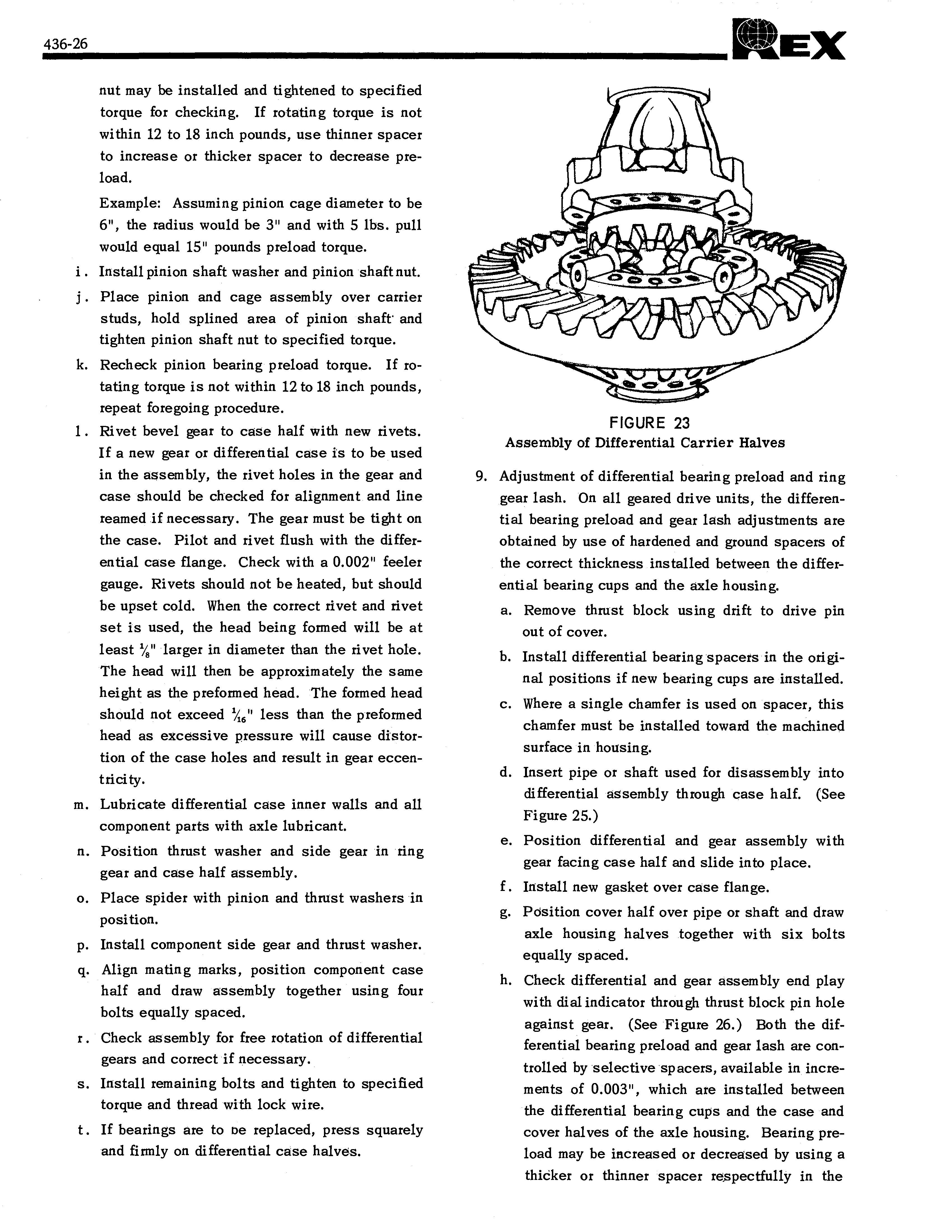
9. Adjustment of differential bearing preload and ring gear lash. On all geared drive units, the differential bearing preload and gear lash adjustments are obtained by use of hardened and ground spacers of the correct thickness installed between the differential bearing cups and the axle housing. a. Remove thrust block using drift to drive pin out of cover. b. Install differential bearing spacers in the original positions if new bearing cups are installed. c. Where a single chamfer is used on spacer, this chamfer must be installed toward the machined surface in housing. d. Insert pipe or shaft used for disassembly into differential assembly through case half. (See Figure 25.) e. Position differential and gear assembly with gear facing case half and slide into place. f . Install new gasket over case flange. g. Position cover half over pipe or shaft and draw axle housing halves together with six bolts equally spaced. h. Check differential and gear assembly end play with dial indicator through thrust block pin hole against gear. (See Figure 26.) Both the differential bearing preload and gear lash are controlled by selective spacers, available in increments of 0.003", which are installed between the differential bearing cups and the case and cover halves of the axle housing. Bearing preload may be increased or decreased by using a thiCker or thinner spacer respectfully in the
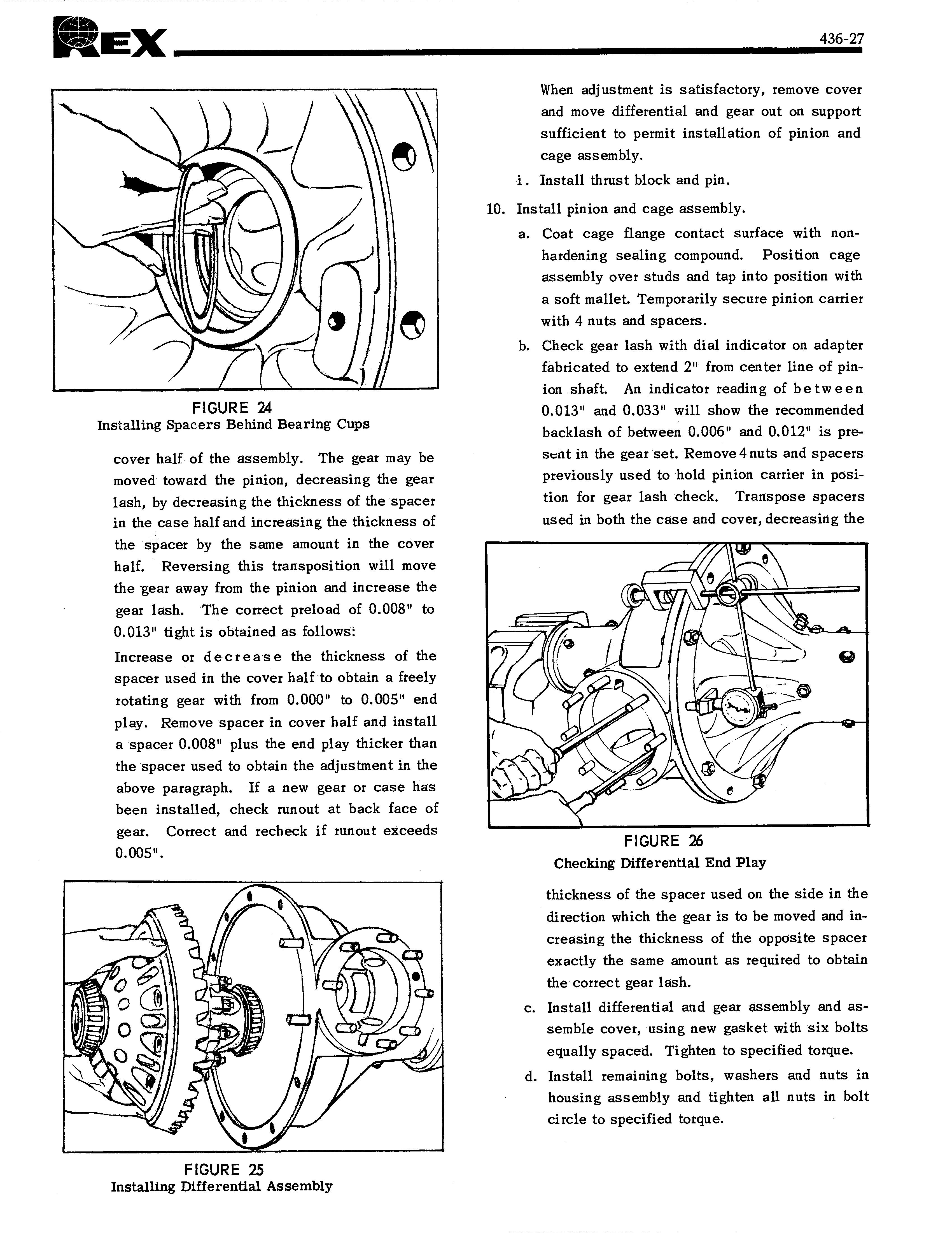
FIGURE 24 Installing Spacers Behind Bearing Cups
cover half of the assembly. The gear may be moved toward the pinion, decreasing the gear lash, by decreasing the thickness of the spacer in the case half and increasing the thickness of the spacer by the same amount in the cover half. Reversing this transposition will move the gear away from the pinion and increase the gear lash. The correct preload of 0.008" to 0.013" tight is obtained as follows: Increase or decrease the thickness of the spacer used in the cover half to obtain a freely rotating gear with from 0.000" to 0.005" end play. Remove spacer in cover half and install a spacer 0.008" plus the end play thicker than the spacer used to obtain the adjustment in the above paragraph. If a new gear or case has been installed, check runout at back face of gear. Correct and recheck if runout exceeds 0.005". When adjustment is satisfactory, remove cover and move differential and gear out on support sufficient to permit installation of pinion and cage assembly. i . Install thrust block and pin. 10. Install pinion and cage assembly. a. Coat cage flange contact surface with nonhardening sealing compound. Position cage assembly over studs and tap into position with a soft mallet. Temporarily secure pinion carrier with 4 nuts and spacers. b. Check gear lash with dial indicator on adapter fabricated to extend 2" from center line of pinion shaft. An indicator reading of between 0.013" and 0.033" will show the recommended backlash of between 0.006" and 0.012" is presfit in the gear set. Remove 4 nuts and spacers previously used to hold pinion carrier in position for gear lash check. Transpose spacers used in both the case and cover, decreasing the