12 minute read
thru 20


VT16 PUMP OVERHAUL
A. DISASSEMBLY (Fig. 9) — Before removing pump — be sure it is not under pressure. 1. Use a puller to remove shaft gears or pulleys to prevent damage to the shaft and bearings. During disassembly pay special attention to identification of parts for correct reassembly. Refer to (Fig. 9) for identification of parts. 2. Cover end — Clamp the pump mounting flange in a vise. Be certain to use protective jaws. a. Remove the tank cover screw, lock washer, washer, guide and guide shaft. Lift off the tank cover and gasket and remove the tank screws, tank, gaskets and spacers. b. Remove the cover screws and separate the cover from the pump. Remove the control valve subassembly and spring and the cover "0" ring. NOTE: Control valve subassemblies are preset and tested at the factory, and should not be disassembled. If any part is defective, the complete subassembly should be replaced. c. Remove the pressure plate. Note the position of the pump ring for reassembly. Pull out the ring locating pins and remove the ring. Remove the vanes from the rotor slots and slide the rotor off the drive shaft. Remove the body "0" ring. 3. Shaft end — Remove the drive shaft key. Remove the bearing retaining snap ring and gently tap the splined end of the shaft to remove the shaft and the outboard bearing. Support the outboard bearing inner race in an arbor press and press out the shaft. Remove the inboard bearing from the shaft end of the body with a bearing puller or by tapping it out from the cover end.
B. INSPECTION, REPAIR and REPLACEMENT —
Discard all used seals and gaskets. Wash all parts in solvent and place on a clean cloth. Soak new seal' s and "0" rings in hydraulic fluid prior to assembly. 1. Cartridge, Body and Pressure Plate — Inspect all wearing surfaces for scoring. Light scoring can be removed from the body and wear plate with crocus cloth or by stoning or lapping. Inspect vanes for wear. Vanes must not have excessive play in the rotor slots or burred edges.
Replace the vanes if defective. Check rotor slots for sticky vanes for wear. Vanes should drop in rotor slots from their own weight when both the rotor and vanes are dry. 2. Control Valve Subassembly — Check that the valve moves freely in its bore in the cover and check the valve and cover bore for excessive wear and scoring. Replace both cover and valve subassembly if deeply scored. 3. Bearings — Replace bearings if they are rough, pitted, cracked or scored. 4. Drive Shaft and Seal — Always replace the seal at overhaul. Check the sealing journal on the shaft for scoring. Replace the shaft if it is worn; do not install a worn shaft with a new seal. 5. Body and Cover — Stone the mating surfaces if there are any burrs or sharp edges. Rewash after stoning.
C. REASSEMBLY (Fig. 9) — Immerse all parts in a clean hydraulic oil to facilitate assembly and prevent damage to seals. 1. Shaft End — Carefully seat the inboard (body) bearing in the body by pressing on the outer race. Install the outboard bearing on the shaft by supporting the inner race and pressing the shaft into it. Using a shaft seal driver, install the shaft seal with the lip facing inward. Be sure that both bearings and the seal are properly seated. Lubricate the seal lip with petroleum jelly and slide the shaft into position. Install the snap ring in the body. 2. Cover End — Support the body on blocks with the shaft end down before reassembling the pump cartridge and cover. Coat the two large "0" rings with petroleum jelly and install them in the grooves in the body and cover. a. Place the ring against the pump body so that the cam contour is the same as at disassembly and the arrows point in the correct direction of rotation. Install the rotor and insert the vanes in the rotor so that the radiused edges are against the ring cam. Position the pressure plate over the locating pins. Be sure the place is flat against the ring. b. Insert the spring in the cover bore and install the control valve, small land toward
the cartridge. Install the cover over the pressure plate and flush against the ring. Install the cover screws and tighten them to 25-30 foot pounds torque. Turn the drive shaft through by hand to be sure it does not bind.
c. Reservoir — Place the gaskets and spacers on top of the pump and install the tank and tank screws. Torque tighten the screws to 42-48 inch pounds. Plug the ports in the pump cover and fill the reservoir with clean hydraulic fluid poured through a micron filter. Turn the drive shaft several times in the proper direction of rotation to fill all the pump chambers and then refill the reservoir.
Install tank cover gasket and cover. Assemble the bolt guide and gasket and install the guide in the cover. Assemble the lock washer on the cover screw and install and tighten the screw.
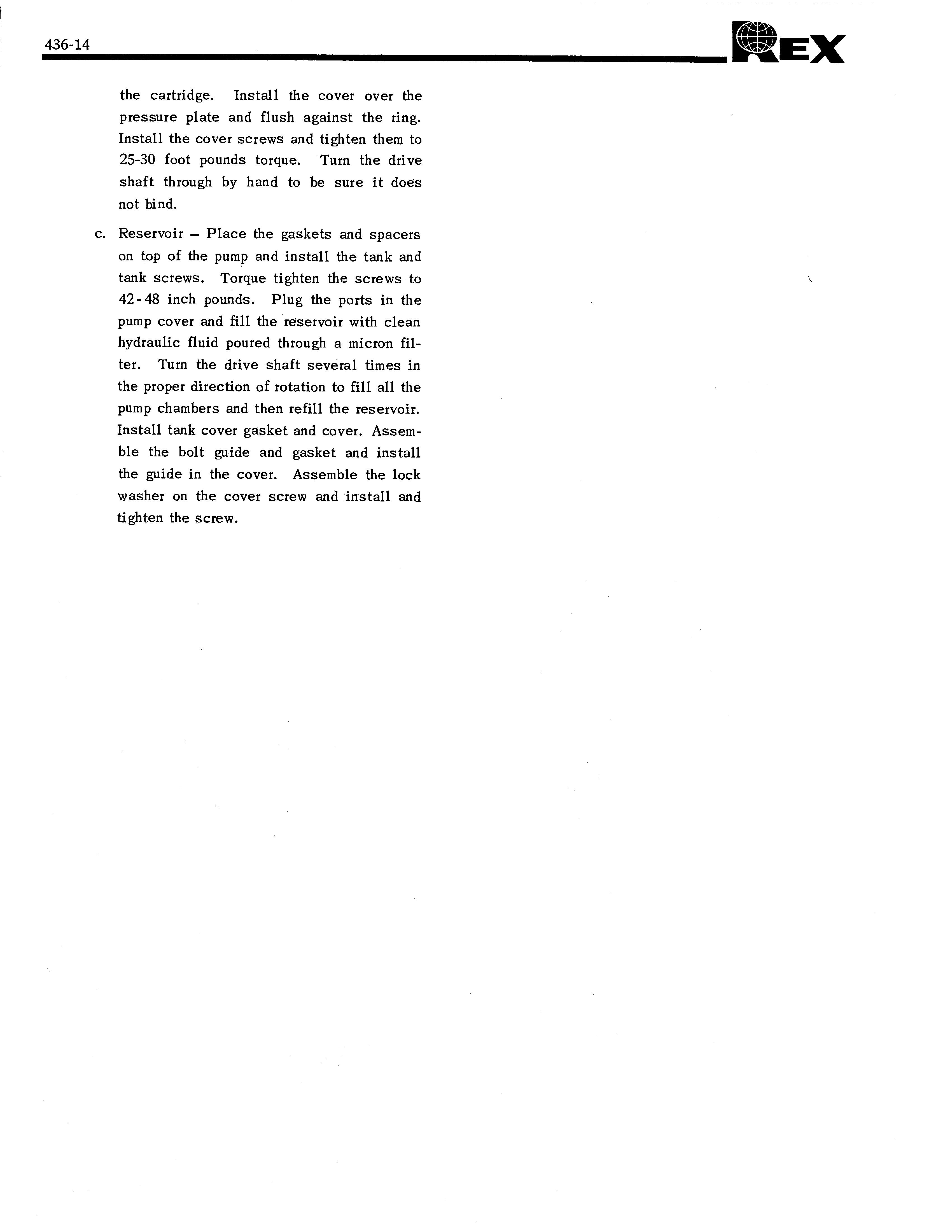
REX POWER CUSHION, FORWARD-REVERSE TRANSMISSION (Model AS2-1120, hereafter referred to as T12
The Power Cushion Transmission is a single range and the drop center distance from input to output is fully reversing power shift transmission. It is used in 4.25 inches. Provision for a slip flange on the output conjunction with a long 11" converter. shaft is made for extremely close coupled installations. The clutches in the T12 unit are contained in one large The output flange slips within a sealed grease cavity balanced drum assembly and the plates drive concen- and not against the output shaft seal. The main case tric shafts. The outer shaft has a gear mounted on it is of two piece cast construction and the rear half conwhich is in direct mesh with the output gear on the out- tains a heavy diaphram midwall which forms one side put shaft. This transmits reverse rotation to the output of a rigid straddle mounted support for the output gear shaft. The inner shaft has a gear mounted on it which and shaft. Oil passages run within the walls of the is in mesh with the output gear through an idler gear. case and no external lines need be provided except for This transmits forward rotation to the output shaft. the cooler and safety seat valve if it is used. Therefore, the drive train consists of only four gears
'05401111MM
MEM
P.P"Ii""14111
1111
IL 1
11111
•111 OM?
n1i111111!,,
TROUBLE DIAGNOSIS — GENERAL
When a transmission malfunction is encountered, the following general procedure will aid in locating the failure. 1. Be certain the transmission is at proper operating temperature (180 0 -200°F.). 2. Check oil level; if low, bring level up to full mark and recheck operation of vehicle. 3. Check external linkage connections to the selector valve and inching control valve. 4 Check inching plunger lock-out. a. Be sure inching plunger is locked out all the way. b. Check two cap screws on inching plunger for over tightness. Over tightness will bind floating valve spool inside the aluminum valve housing. 5. Mount pressure gauges on the transmission at appropriate locations and check for absence or presence of proper operating pressures.
Pressure — Main — 100 -140 PSI. Converter — 55 - 80 PSI. Lube — 12 -30 PSI.
Pump Capacity — 8.7 G.P.M. @2000 R.P.M.
TROUBLE
High stall speed.
Continuously high oil.
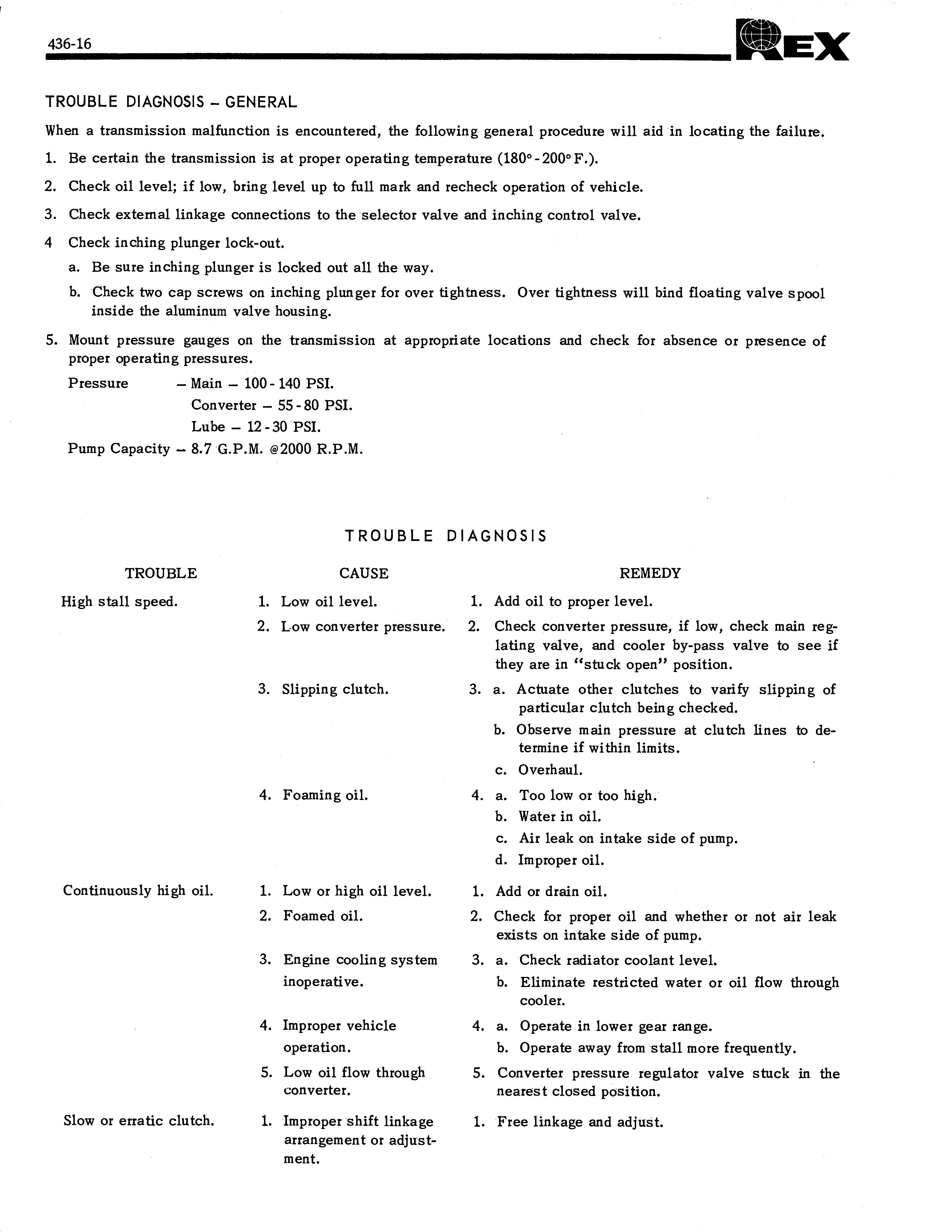
Slow or erratic clutch.
TROUBLE DIAGNOSIS
CAUSE
1. Low oil level. 2. Low converter pressure.
3. Slipping clutch.
4. Foaming oil.
1. Low or high oil level. 2. Foamed oil.
3. Engine cooling system inoperative.
4. Improper vehicle operation. 5. Low oil flow through converter.
1. Improper 'shift linkage arrangement or adjustment. REMEDY
1. Add oil to proper level. 2. Check converter pressure, if low, check main reglating valve, and cooler by-pass valve to see if they are in "stuck open" position. 3. a. Actuate other clutches to varify slipping of particular clutch being checked. b. Observe main pressure at clutch lines to determine if within limits. c. Overhaul.
4. a. Too low or too high. '
b. Water in oil. c. Air leak on intake side of pump. d. Improper oil.
1. Add or drain oil. 2. Check for proper oil and whether or not air leak exists on intake side of pump. 3. a. Check radiator coolant level. b. Eliminate restricted water or oil flow through cooler. 4. a. Operate in lower gear range. b. Operate away from 'stall more frequently. 5. Converter pressure regulator valve stuck in the nearest closed position.
1. Free linkage and adjust.
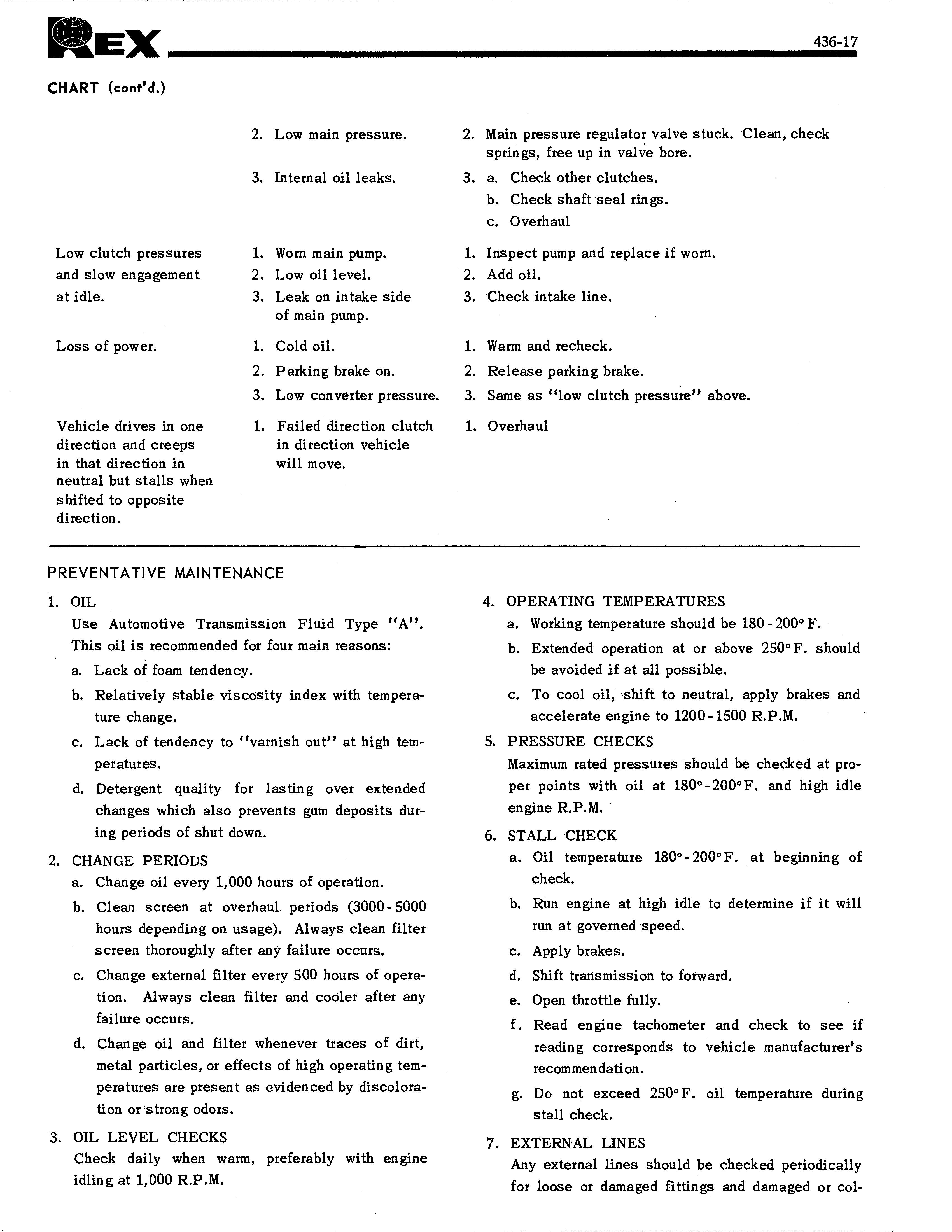
Low clutch pressures and slow engagement at idle.
Loss of power.
Vehicle drives in one direction and creeps in that direction in neutral but stalls when shifted to opposite direction. 2. Low main pressure. 2. Main pressure regulator valve stuck. Clean, check springs, free up in valve bore. 3. Internal oil leaks. 3. a. Check other clutches. b. Check shaft seal rings. c. Overhaul
1. Worn main pump. 1. Inspect pump and replace if worn. 2. Low oil level. 2. Add oil. 3. Leak on intake side 3. Check intake line. of main pump.
1. Cold oil. 1. Warm and recheck. 2. Parking brake on. 2. Release parking brake. 3. Low converter pressure. 3. Same as "low clutch pressure" above.
1. Failed direction clutch in direction vehicle will move. 1. Overhaul
PREVENTATIVE MAINTENANCE
1. OIL
Use Automotive Transmission Fluid Type "A".
This oil is recommended for four main reasons: a. Lack of foam tendency. b. Relatively stable viscosity index with temperature change. c. Lack of tendency to "varnish out" at high temperatures. d. Detergent quality for lasting over extended changes which also prevents gum deposits during periods of shut down. 2. CHANGE PERIODS a. Change oil every 1,000 hours of operation. b. Clean screen at overhaul. periods (3000- 5000 hours depending on usage). Always clean filter screen thoroughly after any failure occurs. c. Change external filter every 500 hours of operation. Always clean filter and cooler after any failure occurs. d. Change oil and filter whenever traces of dirt, metal particles, or effects of high operating temperatures are present as evidenced by discoloration or strong odors. 3. OIL LEVEL CHECKS
Check daily when warm, preferably with engine idling at 1,000 R.P.M. 4. OPERATING TEMPERATURES a. Working temperature should be 180 - 200° F. b. Extended operation at or above 250°F. should be avoided if at all possible. c. To cool oil, shift to neutral, apply brakes and accelerate engine to 1200-1500 R.P.M. 5. PRESSURE CHECKS
Maximum rated pressures should be checked at proper points with oil at 180°-200°F. and high idle engine R.P.M. 6. STALL CHECK a. Oil temperature 180°-200°F. at beginning of check. b. Run engine at high idle to determine if it will run at governed speed. c. Apply brakes. d. Shift transmission to forward. e. Open throttle fully. f . Read engine tachometer and check to see if reading corresponds to vehicle manufacturer's recommendation.
g. Do not exceed 250° F. oil temperature during
stall check.
lapsed hose or tubing. 8. LINKAGE ADJUSTMENT
Close attention should be made to periodically checking selector valve linkage adjustment to determine if the linkage is properly locating the selector valve in relation to its detent positions.
T12 TRANSMISSION SUGGESTED DISASSEMBLY PROCEDURE
With the transmission removed from the vehicle and placed in a suitable working area, proceed with disassembly as follows: 1. Remove cap screws from valve body block and remove from transmission. 2. Mark oil pump and housing to insure proper mate up during reinstallation and remove cap screws holding pump and collector ring to converter housing. 3. Lay transmission on the gear case and remove cap screws holding converter housing to gear case. Lift off converter housing and disc drum assembly as a unit. Be careful not to damage the seal rings in the collector ring on the gear case. 4. Remove the converter housing from the disc drum assembly by removing the snap ring on the turbine shaft and sliding the housing from the drum and
shaft assembly . .
5. Remove the forward gear and forward 'shaft in the following manner: a. Remove cap screws and lock washers holding forward shaft bearing cap and remove cap. b. Remove snap ring on the forward side of the forward gear. c. Tap the forward shaft on the front end while holding the forward gear through the valve block opening and pull the shaft and bearing assembly rearward from the gear box. 6. Remove the reverse gear and shaft in the following manner: a. Remove snap ring on rear side of the reverse gear. b. Identify the collector ring with the gear case to insure proper reinstallation. c. Remove cap screws and lock washers that retain the collector ring and remove the collector ring from the housing. Remove seal rings if excessive wear is noted. d. Remove the reverse shaft and bearing assembly while holding the reverse gear through the valve block opening. 7. Remove idler gear and shaft in the following manner: a. Remove cap screws and lock washers retaining the idler cap to the housing and remove cap and shaft. Be sure to note the position of the pin holding the cap to the shaft to insure proper reinstallation. b. Remove idler gear through the valve block opening. 8. Remove output gear and shaft in the following manner.