1 minute read
Raymond® Walkie Pallet Truck Maintenance Manual
Component Procedures
Main ON/OFF Switch
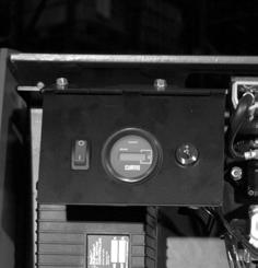
A Main ON/OFF switch (SW13) is provided on the gauge console. See Figure6-12. In the OFF position (O), battery power to all control functions is interrupted. In the ON position (I), battery potential is provided to all control functions via the key switch.
Inspection
1.With the battery plugged in and the Main ON/OFF switch in the ON position, battery voltage B+ should be present on both terminals of the switch.
2.Test the Main ON/OFF switch with an ohmmeter after disconnecting the battery and removing the wires from the switch terminals.
In the OFF position, the ohmmeter should read greater than 1 megohm, and in the ON position, the ohmmeter should read less than 1 ohm. If not, replace the switch.
Removal
1.Disconnect the battery connector.
2.Remove the tractor cover.
3.Remove the gauge console from the electrical panel.

4.Disconnect the wires from the switch.
5.Remove the Main ON/OFF switch.
Installation
1.Install the new Main ON/OFF switch.
2.Connect the wires to the new Main ON/OFF switch terminals.
3.Re-install gauge console onto electrical panel.
4.Reconnect the battery connector and check operation.
5.Install the tractor cover.
Main ON/OFF Switch PDMM-0100 Issued: 5/21/01
Key Switch
A two-position (ON/OFF) key switch (SW1), located on the gauge console, energizes all truck control functions when in the ON position, provided the Main ON/OFF switch is in the ON position. See Figure6-13.

Inspection
1.Remove the tractor cover.
2.With the battery plugged in and the key switch ON, battery vo ltage B+ should be present on both terminals of the switch.
3.Test the key switch with an ohmmeter after turning it OFF, disc onnecting the battery and removing the wires from the switch terminals.
In the OFF position, the ohmmeter should read greater than 1 megohm, and in the ON position, the ohmmeter should read less than 1 ohm. If not, replace the switch.
Removal
1.Turn the key switch OFF.
2.Disconnect the battery connector.
3.Remove gauge console from electrical panel.
4.Remove the mounting nut from the stem of the key switch.
5.Disconnect the wires from the key switch.
6.Remove the key switch.
Installation
1.Install the new key switch and tighten the locking nut.
2.Connect the wires to the new key switch terminals.
3.Re-install the gauge console onto the electrical panel
4.Reconnect the battery connector and check operation.
5.Install the tractor cover.


