8 minute read
Connecting the Dots: Making Wiring and Connection Repairs


Electrical Tape Wrap Grommet
PVC Pipe Silicone Adhesive Fig. 4-20. Acceptable methods of providing abrasion protection through bulkheads.
Advertisement
connections. Sealing heat-shrink tubing works well in these cases. (See the circuit-repair section of this chapter.) All wiring should be routed at least 2 inches (50.8 mm) from wet-exhaust-system components and 9 inches (22.9 cm) from dry-exhaust components.
Methods of securing wire can be as simple as using nylon wire ties with screw holes for attachment. The recommended method of securing wires running above or near moving machinery is to use the plastic-dipped or rubber-insulated metal fasteners commonly found on standard engine installations. Figure 4-21 on page 60 shows a variety of acceptable wire-securing devices.
In making repairs to existing wiring or building a new circuit for the latest electrical appliance you’ve purchased, proper techniques and components can make all the difference in the world when it comes to preventing problems later. Take the time to do the job right and do it once.
Soldering Terminals
Over the years there has been some controversy and discussion among electricians regarding soldering versus crimp-type connectors used in electrical wiring on boats. For years I labored over each con-
Fig. 4-21
Fig. 4-21. Tie-wraps and other acceptable clamps for securing wiring harnesses.
nection, carefully soldering each lead. I considered crimp-on terminals to be the easy way out and inferior to soldered terminals. Well, times have changed and so has my view of the proper way to attach terminals to the ends of wires. In fact, I no longer use solder for any of my connections. Crimp technology has improved significantly so that if the crimps are applied correctly, you won’t have any problems with them at all. Premier boatbuilders are using crimp connections exclusively with no problems, and I’m now convinced that crimping connectors is more practical than soldering them. It’s certainly a lot more time-effective.
Once again, our friends at the ABYC have provided some guidance. In their view, solder must not be used as the sole means of connecting terminals to wire. The connection must first be mechanically fastened (crimped) and then soldered. They do make an exception, however, relating to battery terminals: Battery terminals may use only solder as long as the cable enters the terminal at a minimum distance of 1.5 times the diameter of the conductor (the battery cable itself). This is shown in figure 4-22.
The reasoning behind the ABYC’s crimp-plus-solder recommendation for connections may not be clear to the novice electrician. Excessive current can generate enough heat in a poor-quality connection to melt the solder, allowing the terminal to come undone. I recommend that you stick to crimping, following the guidelines given here.
First select the correct terminal. Figure 4-23 shows the preferred types, all “captive” by definition. “Captive” means that if the screw or nut holding them in place comes loose, they won’t fall off the shank of the screw or stud. The figure also shows some types that should never be used. Don’t ever wrap the bared end of a wire (without a properly attached terminal) around a screw and tighten it in place. With stranded wire (the only type you should be using) it’s quite easy to have some of the strands squeeze out, and they can end up touching an adjacent terminal, causing a short circuit.
X
Fig. 4 -22
Fig. 4-22. The rule for soldering battery cable ends.
Unapproved wire connector
Approved wire connectors
Fig. 4-23. Preferred types of connectors, and types that are not allowed.
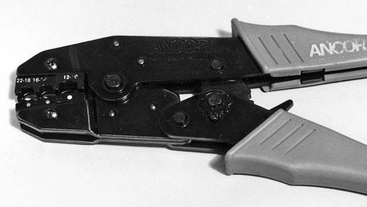
Fig. 4-24. Ancor ratcheting crimper. By using this type of crimper, you can be assured that all your connections will be crimped properly as long as you use the tool correctly.
When selecting terminals, refer to the color codes and match the terminal color to the appropriate wire gauge. The colors are as follows: Red 18–16 gauge Blue 16–14 gauge Yellow 12–10 gauge Burgundy 8 gauge
Never crimp a wire into a larger terminal that’s not the correct size. Either the connection will not hold or you’ll lose some of the strands in the wire, creating an increase in resistance.
Crimping tools have changed over the last few years. Today’s ratcheting crimping tools do a fine job and take away the big question, did I squeeze the pliers hard enough? These crimpers are easy to use; all you do is squeeze the handles until the ratchet snaps, and you can be sure the connection has been squeezed hard enough.
One disadvantage to these new crimpers is that manufacturers have designed them to use only their own terminals. Thus, you can only be certain of the integrity of the crimp if you use terminals designed to match the crimper. This is not a huge problem if you buy your supplies at the same place you bought the crimper, but be aware that the crimper you buy may not be compatible with all brands of terminals. Figure 4-24 shows my crimper, made by Ancor.
For wire stripping, I use the end-type stripper shown in figure 4-25. This stripper is adjustable so that the exact amount of insulation can be removed from multiple pieces of wire, and the risk of cutting into the wire strands is minimized.
Both the crimper and the wire stripper are available through West Marine and all the major marine supply stores. At about $140 for the pair, this combination is a really good investment and will make your work much easier. Figure 4-26 shows the stripper in use, and figure 4-27 shows the crimper in use.
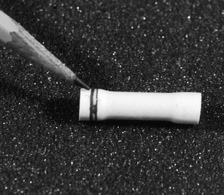
About 1⁄4 inch (6 mm) of insulation should be stripped off the wire before it’s inserted into the terminal ferrule. The stripper mentioned above allows you to set the amount of insulation to be removed in millimeters. The correct match of wire and connector is illustrated in figure 4-28. The ends of the wire just barely protrude from the ferrule of the terminal.
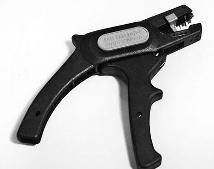
Fig. 4-25. End stripper. I love these tools because you can adjust the amount of insulation to remove for a really good match to the crimp connector. One drawback is that they only work on wire up to 10 AWG.
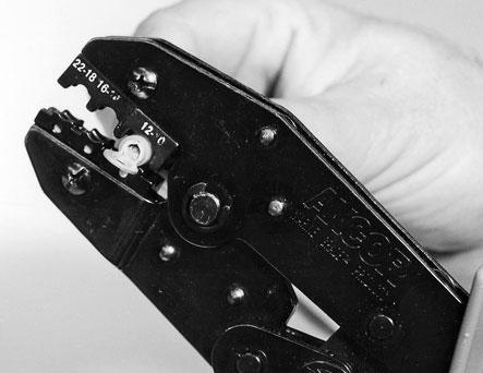
Fig. 4-27. Ratcheting crimper in use. Fig. 4-26. End stripper in use.
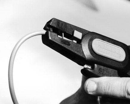
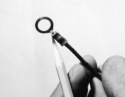
Fig. 4-28. The correct amount of wire protrusion through the barrel of the connector.
Make sure the crimper is in proper orientation with the terminal. For all but the butt-type connector, the handles of the crimping tool must be in the same plane as the ring or blade of the terminal, as shown in figure 4-29. For butt connectors, this really doesn’t matter, but be sure both crimps align in the same plane. Always test your crimps by pulling on the wire hard enough to be sure they’ll hold.
The newest variety of crimp terminals comes with heat-shrink casings preinstalled. After you crimp the terminal to the wire, heat the terminal with a heat gun, and the insulation will shrink tight around the terminal and seal it against moisture. This is a superior method of applying a terminal to a wire, but these terminals cost approximately a dollar each at this time.
When splicing a group of wires in a harness, it’s a good idea to stagger the butt connectors so you don’t end up with a bunch of them in one spot. Figure 4-30 illustrates what can happen. A better approach is shown in figure 4-31.
At some point you may find yourself having to repair or replace a gang plug. There are many types of these plugs available, and it’s usually best to replace the entire plug assembly rather than to replace a single connector within the assembly. Replacing only a part of the plug rarely works and the watertight integrity of the plug is almost always ruined. Duplex and triplex assemblies are available at the major supply houses, and repairing these may also require replacing both the male and female ends of the plug.
Fig. 4-29
Fig. 4-29. Orientation of the plier jaws with the connector to make a proper crimp.
g
Fig. 4-30. A “bunch” of butt connectors at a harness repair point. Taped and wrapped as it should be, this would look like a snake trying to swallow a rat!
Fig. 4 -31
Fig. 4-31. Staggered butt connectors at a harness repair point. Using this approach to harness repair will give a much neater job.
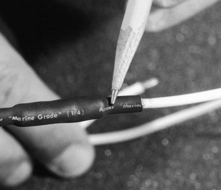
Fig. 4-32. Butt connection with waterproof heat-shrink tubing. This is the highly recommended method for joining two wires together, especially in the area of the bilge. Fig. 4-33. “Stepped”-type butt connector. These are the only way to go when you need to join two wires of different gauges.
Finally, whenever you join two wires with butt connectors, I strongly recommend that you seal them with a length of heat-shrink tubing to make a watertight connection. These terminals are famous for trapping water and corroding. Figure 4-32 shows a butt connector that has been crimped and sealed with heat-shrink. Heat-shrink tubing is now available with a sealer that’s perfect for making waterproof connections anywhere on board.
Another new addition to the electrician’s arsenal is the dual-gauge butt connector. These stepped connectors provide a solution to the age-old problem of connecting a smaller wire to a larger one. Figure 4-33 shows one of these new connectors.