6 minute read
Galvanic Isolators


AC Generator Troubleshooting Guide
Aside from these basic checks, some more advanced procedures are found in the following checklist. These additional checks are too advanced for most beginners and will have to be carried out by a trained technician, preferably one certified on your particular brand of generator.
Low Voltage
Check the voltage at the generator. If the reading is OK and your panel meter is reading low, there is an excessive voltage drop in the wiring between the generator and the panel.
Verify correct generator engine rpm and governor settings.
Check all connections and wire terminations for integrity. First make sure the generator is off!
If voltage is OK until the engine warms up and loads are applied, the generator voltage regulator and related circuitry are at fault.
The voltage regulator may need adjustment or replacement.
High Voltage
Check the frequency for normal range (between 57 and 63 Hz in the United States).
If possible, adjust the voltage regulator.
Verify correct engine rpm and governor adjustments.
Erratic Voltage
The generator brushes could be worn or burned.
There could be internal wiring problems or loose connections.
Erratic Frequency
Check for loads cycling where the generator turns the current on and off. If the frequency is erratic with all loads turned off, check the governor for proper operation. Can you hear subtle rpm changes?
High Frequency
Have the governor operation checked.
Low Frequency
Turn off all loads. If frequency returns to normal, the generator is being overworked and is probably underrated. Either give up some AC toys or prepare to upgrade to a bigger generator.
Check for faulty governor adjustment.
Galvanic Isolators
A device that has become increasingly popular in recent years on new boats is the galvanic isolator. The trouble with them is that most folks, including many marine electricians, haven’t the faintest idea what they do. So, what are these things used for anyhow? Well, here’s the definition: “A device installed in series with the green grounding conductor of the shore-power cable which effectively blocks galvanic current flow (DC), but permits the passage of alternating current (AC).”
You’re probably still wondering, Yeah, but what does it do? Why do I need one?
If you spend much time at the dock plugged into shore power, you need a galvanic isolator. Here’s why: Galvanic current flow is a danger at any marina, putting your boat at risk of galvanic corrosion. The more boats with AC shore power, the greater the risk. Your boat could be in great electrical shape, but once plugged into shore power it becomes electrically connected to its neighbors via the green grounding wire in the AC system. This connection completes an electrical circuit between multiple boats, each with potentially dissimilar underwater metals exposed to the surrounding seawater. What’s created is a giant battery and the potential galvanic corrosion that can result. Further, it is also possible to transfer higher-voltage DC stray current from one
boat to another in this situation. This could generate stray-current corrosion.
How can that be? You might have thought the AC and DC systems were completely separated on your boat. They are, except for one common point where the DC and AC grounding system are tied together. Any faults that induce current flow in this normally non-current-carrying conductor can potentially be transferred via this green wire. This stray current can cause excess corrosion, rapid deterioration of underwater sacrificial zincs, and, in the worst case, can cause underwater metal appendages from your boat to literally dissolve in seawater. A common cause of stray-current corrosion is wiring that uses a boat’s electrical bonding system as the DC ground for various appliances—typically bilge pumps. Any live wire hanging in the bilge water could be the culprit.
The only direct path for stray current to flow beyond any individual boat is via the green grounding conductor in the AC shore-power system (that is, except for a leak into the water surrounding the boat). It’s important to note that the galvanic isolator is designed to isolate only low-level galvanic DC current. Its purpose is to block only about 1.4 volts or less, not a full 12 volts. All precautions must be taken to ensure this green wire never has high-level current trying to find ground through it unless an AC system fault occurs. The isolator is intended to block only the natural galvanic current that will try to pass due to the electrically connected dissimilar underwater metals discussed.
The isolator uses four heavy-duty diodes, often combined with a capacitor, to absorb any voltage surges that may occur. These diodes use their inherent resistance and one-way capability to effectively block any small amounts of DC flow. (Galvanic current is measured at less than 1,200 millivolts, or 1.2 volts.) If a fault in the boat’s AC system develops and the green conductor must be put into real service, AC can easily overcome this resistance and will flow through the isolator.
Rememberthatthegreenwireisdesignedtoprotectagainstshock,anditsintegrityisofparamount importance.Sincetheisolatorismountedinseries withthegreenwireasthefirststoppasttheshorepowerconnectoronyourboatandisoftennoteasily accessible,theisolator’sintegritymustbeknownat alltimes.Ablowndiodeinsidethe isolatorcouldhavethesameeffectas clippingoffthethird groundingterminalonan extensioncord,asmentionedearlier. In consideration of all this, the current version of ABYC Standard A-28, Galvanic Isolators, mandates a status-monitoring device for a galvanic isolator. Both Guest and ProMariner make such devices, which consist of a remote panel that alarms if a failure occurs. These monitors also seem to do a very good job of identifying other electrical problems, often with the dock wiring the boat is plugged into. This has been such a problem that an ABYC committee is now considering a new type of isolator that is rated as electrically “fail safe,” meaning that if a diode
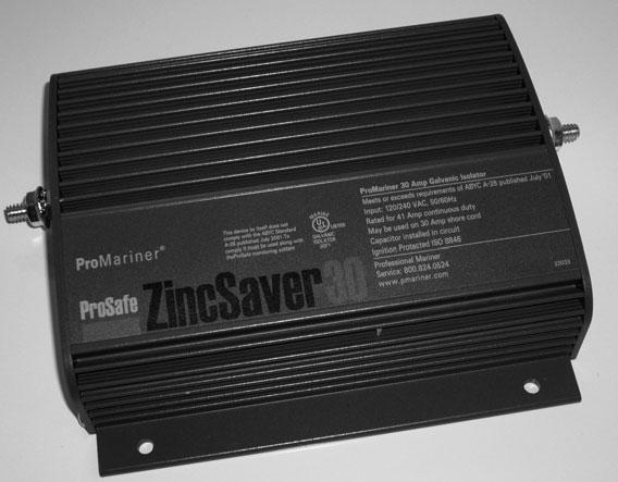
Fig. 11-23. A ProMariner galvanic isolator.
fails,electrical continuity through the device cannot be compromised. As of this writing, the committee has not finalized a new draft of the standard for review. Rest assured that boating magazines will publicize the final decision.
Ifyou’reuncertainwhetheryourboatevenhasa galvanicisolator,checkwithyourdealer.Ifyoucan getatthewiringonthebacksideofyourshorepowerinlet,tracethegreenwirethroughtotheAC masterpanel.Iftheboathasanisolator,itwillbe mountedhere.Figure11-23showsaProMarinergalvanicisolator,whichusesacapacitor,installedonthe greenwire.
Testing Galvanic Isolators
A simple test to make sure your galvanic isolator is working as it should, once you’re certain you have one, is to use the LED tester shown in figure 11-9 on page 167to determine if an open circuit exists in the grounding conductor.
If all the connections and the wiring are intact between your AC panel and the shore-power box, an open indicates either a break in continuity inside the galvanic isolator or a problem on the dock. Have the marina operator verify the condition on the dock. If it’s OK, you may have a faulty galvanic isolator. Any ABYC-certified electrical technician can check this for you if you have any doubts.
Figure 11-24shows the correct location for the galvanic isolator in relation to your shorepower inlet and the AC panel on your boat. If your boat doesn’t have a galvanic isolator installed and you spend a lot of time at the dock, it would be a good upgrade to any AC electrical system. You can do this one yourself rather easily. Just make sure that the isolator you select is rated for the proper amperage (at least the same as your boat’s AC rating or more), and preferably with a built-in capacitor for added protection to the unit itself. Also remember to mount these units in a spot that’s relatively easy to get at and will offer good ventilation.
Remember that this chapter is not intended to make you an expert high-voltage electrician. It’s intended to give you a little confidence for basic system checks and to enable you to talk with a marine electrician as an informed consumer. If you still get nervous around shore power, stay away from it! Call in the experts. Underground Conductor (Black)
Shore Connection Grounded Neutral Conductor (White) Grounding Conductor (Green)
Shore Power Cable Connector Shore Power
Cable
Power Inlet (Electrically insulated from the boat if isolator is installed) Main Shore Power Disconnect Circuit Breaker Optional 2 Pole, 3 Wire Grounding Galvanic Isolator Type Plugs &
Receptacles Shore Side Boat side To Engine Negative Terminal or its Bus
Transfer Switch GEN–OFF–SHORE Black White Green
Branch Circuit Breaker (Typical)
120 VAC Grounding Type Receptacle Generator Main Circuit Breaker
120 VAC Generator Fig. 11-24. Diagram of the galvanic isolator between the shore inlet and the AC distribution panel. The galvanic isolator must always be the first device installed in series with the green wire as it enters your boat. (© ABYC)

