8 minute read
Wire Identification and the ABYC Color Code


OPT. SHORE OPT. AC OUTLET
MASTER
Advertisement
SWITCH OPT. NO.2 BATTERY
OPT. AC OUTLET
SHORE POWER BREAKERSWITCH OPT. AC OUTLET OPT. AC OUTLET
Fig. 2-3
Fig. 2-3. A typical, poor-quality diagram. This is all that came with a sailboat that I purchased in the early 1980s to describe the electrical installation. The problem is certainly not exclusive to sailboats!
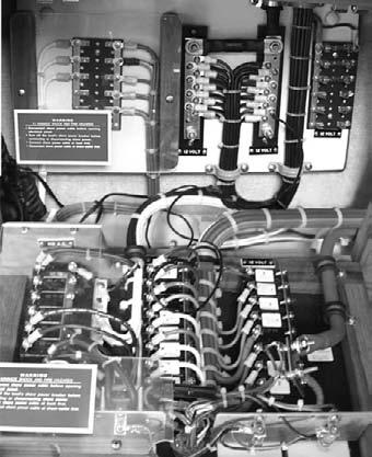
Fig. 2-4. A switch panel with key components identified.
components do, refer to the glossary at the back of this book.
Identifying the wires that connect the various components illustrated by a wiring diagram can sometimes be a challenge when you first get started. The good news here, however, is that our friends at the ABYC have developed a standard color code for boat wiring that brings order to this previously mind-boggling task. This color-coding scheme, which has been around for twenty-odd years, is finally catching on.
The ABYC color code assigns a specific color of wire to each function in a properly wired marine electrical system. Thus, an electrician who is working on a boat wired to the ABYC standard and is confronted with a dark blue wire knows immediately that that wire is for the interior lights and nothing else. He or she also knows that the purple wire is for the ignition system, and that all those red and yellow wires are the DC-positive and -negative connectors. This standard makes it easy to identify a wire’s function in the system on any boat, not just your own, even without the help of a wiring diagram.
Negative Bus Bars
Circuit Breakers/Switches
Positive Bus Bars
Fig. 2-5. ABYC-recommended color codes from their E-11 standard. (Courtesy ABYC)
Figure 2-5 at left lists the ABYC’s recommended color codes and the circuits (or parts of circuits) they serve, as found in Standards and Technical Information Reports, Standard E-11, tables 14 and 15. If your boat is wired to the ABYC’s recommended standards, you can get a jump start in deciphering what you see behind your distribution panel by using this table.
By now you may be saying to yourself, “Hey, this is great—but wait, as I look behind my distribution panel I see 20 red wires and 20 yellow ones [or black ones on an older boat] and several each of about a dozen other colors. What do all these wires do and which one feeds which circuit?” All you know from the table above is that the yellow (or black) wires are supposed to be DC-negative conductors, the red ones should be DC-positive conductors, green ones are ground wires, and light blue ones are for the instruments. But as you sort through this spaghetti, how do you tell just exactly what each wire does? Your boat may not use the ABYC-recommended colors in its wiring, or it may only use some of them. Also, as with most changes, initial acceptance of the color-coding standard when first introduced was neither universal nor overwhelming. Most manufacturers have implemented the changes gradually as they updated their assembly procedures and as stocks of existing wire were depleted. Also, it’s important to note that the ABYC standard allows for deviation from the recommended color scheme as long as all wiring is identified in some way. Many builders have adopted a numbering scheme that positively identifies any wire with numbered labels affixed to the wire; a wiring diagram for the boat then lists the numbers and identifies them. The standard also allows for color substitution as long as a wiring diagram is supplied to identify the wires positively.
If you own one of these older boats or a new one that doesn’t comply with the ABYC color-coding standard, the only answer is to go through the entire electrical system and write down the color and function of each wire. This isn’t as hard as it sounds, and I show you how to do it at the end of this chapter.
Fortunately, compliance with the standard is now nearly universal, and the odds are that if you’re buying a new boat, both the boatbuilder and the engine manufacturer will have complied. This is good news, of course, but even if your wiring system is in compliancewith the ABYC recommendations and you have a comprehensive wiring diagram, you still don’t know what all those multicolored wires in back of the distribution panel do. This brings us to circuit identification, a procedure that’s a little different than wire identification.
A Note on Engine-maker Compliance and the ABYC Color Code
It's important to note that the ABYC standards are recommendations only, and should not be confused with the National Electric Code (NEC), the mandatory safety standards for land-based electrical installations developed and published by the National Fire Protection Association (NFPA). Mercury Marine is one of the few engine manufacturers that actually follows the ABYC-recommended color codes. But since all engine makers provide comprehensive wiring diagrams with their products, they are still compliant with ABYC standards.
Circuit Identification
Circuit identification will help you to determine the specific function of each wire in back of your switch or circuit-breaker panel (which, for consistency, let’s call the distribution panel) or any wire on the boat for that matter. There are several accepted methods for identifying circuits, but unless the manufacturer of your boat was unusually considerate, you’ll have to come up with a system and install it yourself. The technique is called “wire chasing” in electro-speak, and it simply involves following a specific wire from one end to the other and placing some means of identification on the wire as you go.
First learn to concentrate on the circuit in question; forget about all those other wires for the time being. Fortunately, circuit identification is one of the easiest ways to become familiar with the details of your system. Here are a few methods you can use.
Numbered Labels
On the off chance the manufacturer of your boat was unusually meticulous and provided circuit identification, this is the method they probably used to do it. Numbered circuit ID labels come in pads available in any electrical supply house. They are simply clear plastic peel-and-stick labels with white or black numbers
printed on them (black for the white and light-colored wires, and white for the black and dark-colored wires). To use them, first identify the circuit you want to label by the nameplate on the front of the distribution panel adjacent to the switch or circuit breaker. (It will probably say something generic like “accessories.”) There are usually five or six labels of each number in a set, so all you need do is place a number on the first wire behind the switch panel, then trace the wire to the fixtures that it operates. Place labels at strategic places along the wire as you go. Next, trace the yellow or black wire back to the common bus (which should be located somewhere near the distribution panel) and label it the same way. Now write that circuit number down someplace handy and move to the next circuit. If you already have a wiring diagram, you should also write the new circuit number on the corresponding circuit on the diagram.
Now you know that the circuit on the switch panel marked “accessories” is circuit number 32 and it feeds the light in the forepeak and the exhaust fan in the head. If either if these appliances should stop working, all you need do is trace wire number 32 until you find the problem.
Named Labels
Several manufacturers make label sets that you can use just like the numbered labels. They simply state just what fixture or fixtures a specific circuit operates. Named labels have the advantage of not requiring a key to translate the number into a function, but they also have several disadvantages. For one thing, they are not as neat and tidy as the numbered labels, and most circuits will have more than one function, requiring more than one label. You can get around this last objection by simply writing your own labels on white electrical tape with a permanent marker and wrapping it around the wire, but it still is a bit messy, especially on large or complex systems. The labels also tend to fall off if exposed to solvents or fumes.
Colored Heat-Shrink Tubing
A great way to identify circuits is to provide each one with its individual color code applied with heatshrink tubing. By using two colors for each circuit, you can ID up to 25 separate circuits with only five separate colors; if you use three colors for each circuit, the total number of circuits jumps to 125. The big drawback to this system is that each wire must be disconnected at both ends before the heat-shrink can be applied, so it’s very labor-intensive when applied to an existing system. However, it’s fine for additions to existing systems and when a boat must be completely rewired.
Colored Tape and Wire Ties
You can, of course, apply the same color designation as described above using colored electrical tape, which is easy to apply without disconnecting any of the wires. The trouble with tape is that it isn’t as permanent as heat-shrink and it’s liable to wash off if exposed to fuel, solvents, or lubricants (such as WD-40). You can do the same thing using colored wire ties, which are a little bit messier but tend to be more permanent.
There are many other methods for wire identification that are acceptable and are often used by both boat builders and owners. The ABYC standard only states that some means of identifying the wires in each circuit should be employed. All of the above methods are quite acceptable and are good alternatives for any work you may do, such as adding on new equipment.
Whatever means of circuit identification you select—numbered or named labels, colored heatshrink tubing or tape, or a new one that you think up for yourself—of this you can be sure: knowing what every wire on our boat does, where it goes, and where it comes from is going to make your boating life much simpler when problems crop up.
Substituting Wire Colors
Before we leave this fascinating discussion of component identification, we need to cover one other situation that might arise while you’re working on your new ABYC-compliant wiring system. What if you need to replace the 14-gauge brown wire that connects your generator to the alternator, and the only colors you have in your tool box are orange and yellow? This brown wire is only 3 feet long, and the electrical supply house which might or might


