Working with Wiring Diagrams
OPT. AC OUTLET MASTER SWITCH
OPT. NO.2 BATTERY OPT. AC OUTLET
OPT. SHORE
OPT. AC OUTLET
SHORE POWER BREAKER SWITCH
OPT. AC OUTLET
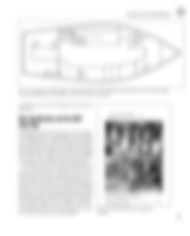
Fig. 2-3 Fig. 2-3. A typical, poor-quality diagram. This is all that came with a sailboat that I purchased in the early 1980s to describe the electrical installation. The problem is certainly not exclusive to sailboats!
components do, refer to the glossary at the back of this book.
Wire Identification and the ABYC Color Code Identifying the wires that connect the various components illustrated by a wiring diagram can sometimes be a challenge when you first get started. The good news here, however, is that our friends at the ABYC have developed a standard color code for boat wiring that brings order to this previously mind-boggling task. This color-coding scheme, which has been around for twenty-odd years, is finally catching on. The ABYC color code assigns a specific color of wire to each function in a properly wired marine electrical system. Thus, an electrician who is working on a boat wired to the ABYC standard and is confronted with a dark blue wire knows immediately that that wire is for the interior lights and nothing else. He or she also knows that the purple wire is for the ignition system, and that all those red and yellow wires are the DC-positive and -negative connectors. This standard makes it easy to identify a wire’s function in the system on any boat, not just your own, even without the help of a wiring diagram.
Negative Bus Bars
Circuit Breakers/ Switches Positive Bus Bars Fig. 2-4. A switch panel with key components identified.
15


